

Page 1
Data Sheet
g
4LSL
Loudspeaker Function Card
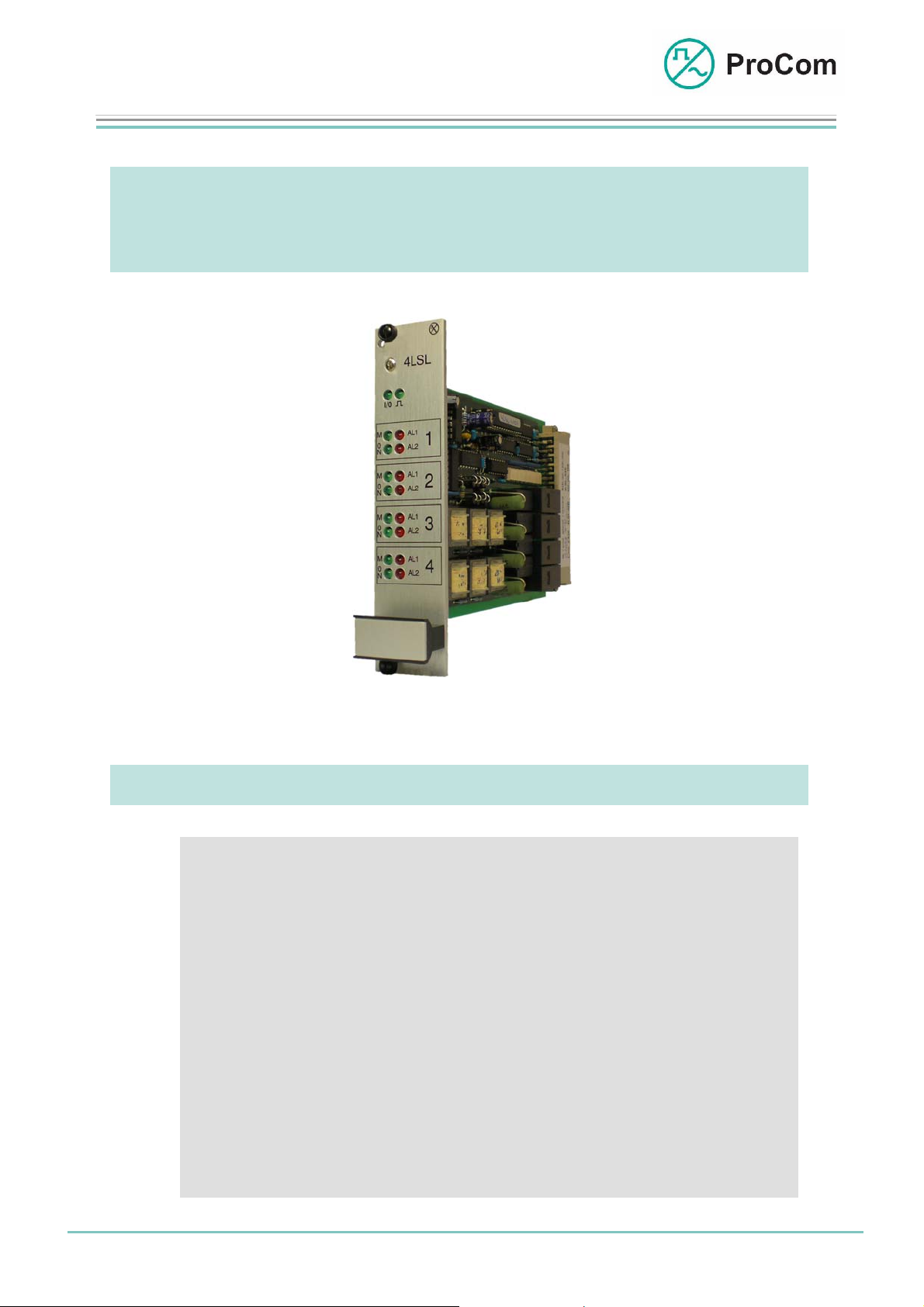
4LSL
At a Glance:
• Active monitoring of impedance on 4 independent LF
channels (configurable deviation thresholds from 1% to 99%)
• Short circuit and wire break recognition
• Ground connection message (recognition through TG01)
• Minimum load and overload monitoring
(2.5 W>=load<= 150 W)
• Distribution of loudspeaker circuits through independent
• Generation of positive or negative public address ac-
Loudspeaker Impedance Monitoring
Fig. 4LSL (L- No. 2.830)
and allocation of the loudspeaker circuit
power relays
knowled
ements
Date:
13.03.2009
Page:
1/7
© 2008 ProCom, All rights and technical changes reserved
Author: HS Document-No.:
DB_4LSL_2830_01
Page 2
Data Sheet
A
V
V
V
4LSL
Loudspeaker Function Card
In order to make a public address announcement it is necessary that the loudspeaker circuits to be used are in functioning order. One way to gauge this is to
use the impedance which was measured during commissioning.
The 4LSL can be used to cyclically check loudspeaker circuits for deviations in
impedance.
To do this a measurement signal is required which is generated by the TG01
module. The functionality of the signal generator is also tested before each
measurement cycle by the 4LSL.
Brief Description:
The 4LSL is part of an application for monitoring impedance in loudspeaker circuits and distributed loudspeaker circuits. It switches the sine wave generated by the
test signal generator to the loudspeaker circuit and compares the flow of current and
the voltage with previously made reference values.
DTA-012 -030/ -048/ -066/ -084/ -114
* TW = Twin Wire
WPS-04
WPS-08
2TW *
DSS1
CPU1
SV01 4NS
DVS-21
TG01
4LSL
100
100
100
Havarie
LC2 ..
LC 1
LC 2
LC n
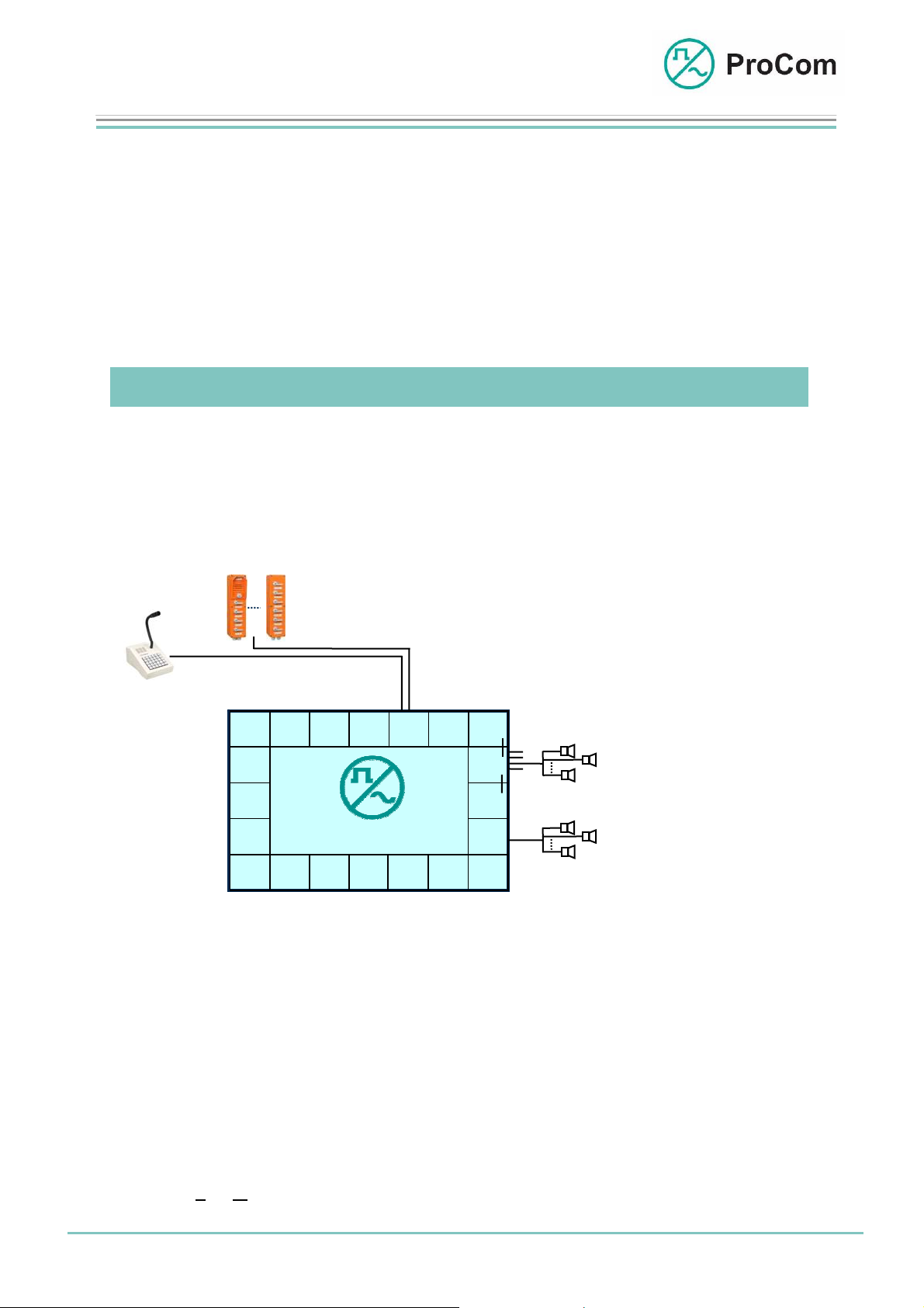
Monitoring of loudspeakers according to the
equipment level 1 of the Deutschen Bahn AG
LC 1
LC 2
LC n
Application example of loudspeaker circuit monitoring
Date:
13.03.2009
Page:
2/7
Author: HS Document-No.:
© 2008 ProCom, All rights and technical changes reserved
DB_4LSL_2830_01
Page 3
Data Sheet
Amp
4LSL
Loudspeaker Function Card
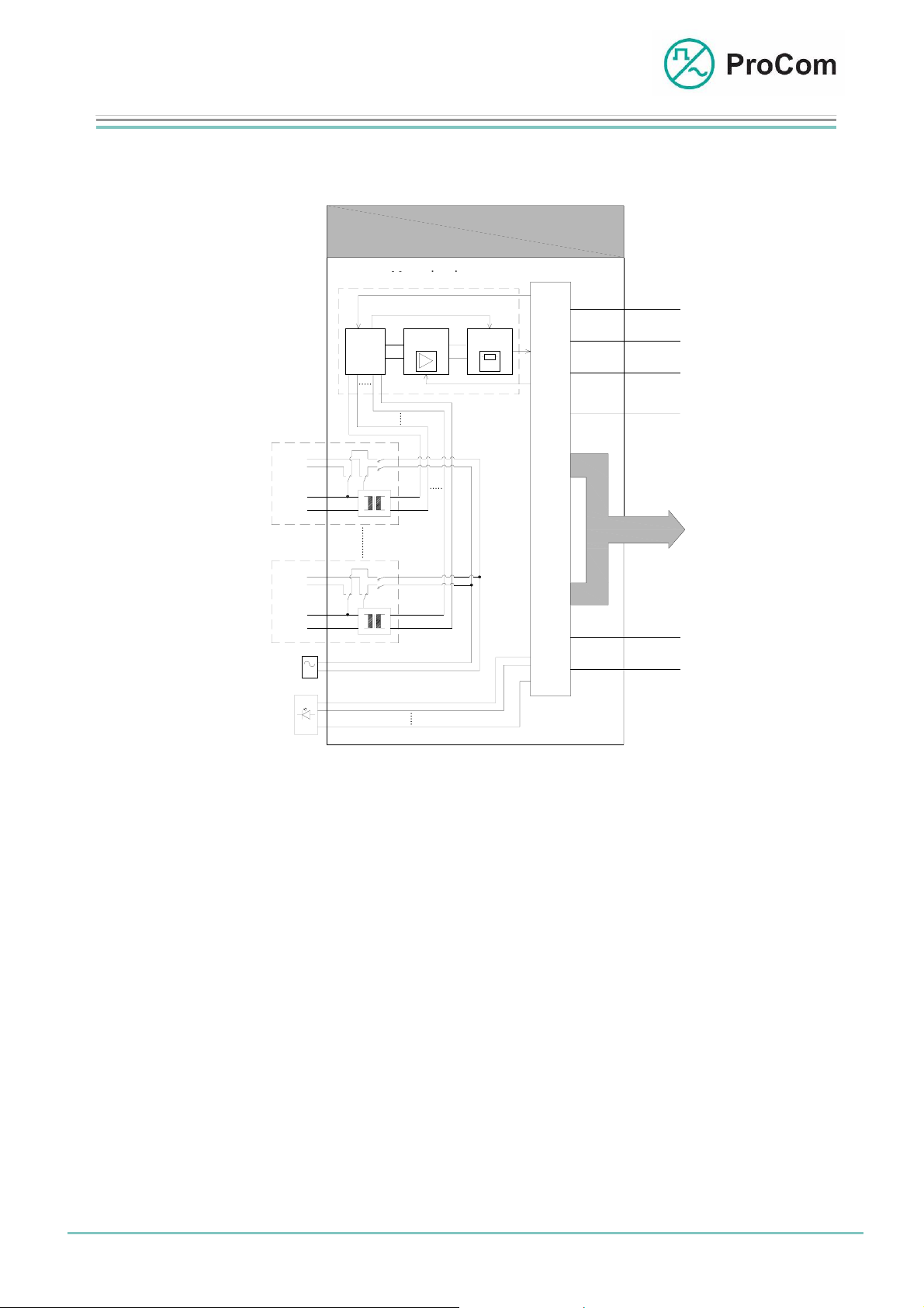
The principle functions are illustrated in the following block diagram.
4LSL
Measuring Circuit
Messkreis
Kopplung
MUX
2 x 4-
2
x 4- Kanal
Chanel
U
I
Coupling
Mess-
Msgmt.
lifier
verstärker
U
I
Mess-
Msgmt.
Evaluator
auswerter
(Z)
S
t
C
e
O
u
N
T
e
R
r
O
u
L
n
P
C
M
Satz 1
Set 1
V 1
(V100)
LK 1
Set 4
Satz 4
V 1
(V100)
LK 1
U
I
U
I
U
I
U
I
g
TG01
G
I
n
A
d
n
i
z
c
e
a
i
t
i
g
o
e
n
Block diagram 4LSL
The 4LSL consists essentially of a control unit, a measuring circuit and 4 independent sets. Each set has a low frequency (LF) input (usually from the V100
amplifier) and a loudspeaker output.
Required for the impedance measurement is the measurement signal generated
by the TG01. Locking by the relay ensures that only one action can be carried out
on the set, and that the LF signal does not reach the TG01. The measurement
signal (125 Hz) is given on the loudspeaker circuit. The current flowing there is
added to the measurement circuit through an input transformer and analysed together with the output voltage. All processes are controlled through configurable
programmes in the ICS software.
For a public address system the LF signal is added to the loudspeaker circuit
through an output transformer.
Displays and messages are regulated by the control unit.
Public address and testing in a loudspeaker circuit are blocked off from one an-
other. Public address has higher priority; a test is carried out after a public address.
+5V
GND
-5V
KS
BUS
-48V
+0V
Date:
13.03.2009
Page:
3/7
© 2008 ProCom, All rights and technical changes reserved
Author: HS Document-No.:
DB_4LSL_2830_01
Page 4

Data Sheet
4LSL
Loudspeaker Function Card
Function Description:
The following functions are available on the 4LSL:
Monitoring of Impedance
New installations or changes in a loudspeaker circuit are monitored for changes
in impedance behaviour with the help of the 4LSL module.
For this the installed and manually tested loudspeaker circuit is measured with
the 4LSL module and its impedance is determined. The
Hz audio signal)
ent module (TG01).
required for this is generated and made available by a differ-
reference signal (125
Set 1 of 4
Msgmt.
Circuit
Loudspeaker Circuit
Schematic illustration of impedance monitoring
Measurement of the connected loudspeaker circuit is automatic. For this the audio signal generator is tested for proper functionality as well as the loudspeaker
circuit for falling short of the minimum loudspeaker load and exceeding of the
maximum loudspeaker load
generator is not working properly (
(load >= 2.5 W or <= 150 W). If the audio signal
audio signal monitoring), or if the load of the
connected loudspeakers is outside the indicated limits then this is indicated by the
LED and system messages. Re-measuring is then automatically prevented. Remeasuring only becomes possible with a proper basic measurement.
Date:
13.03.2009
Page:
4/7
© 2008 ProCom, All rights and technical changes reserved
Author: HS Document-No.:
DB_4LSL_2830_01
Page 5

Data Sheet
4LSL
Loudspeaker Function Card
Short Circuit and Wire-Break Recognition
In loudspeaker circuits
by external effects and which lead to the outage of the loudspeakers. Short circuits or wire breaks are detected and signalled by the 4LSL module during each
subsequent measurement of the loudspeaker circuit.
When the service technician does the commissioning of the measuring module,
Loudspeaker Circuit Safety Switch-off” [LK- Sicherheitsab-
] can be activated. If a short circuit has been detected then it results
Earth Leakage” [Erdschluss] is displayed and the passed on to
Page:
Date:
the function “
schaltung
in a safety switch-off of the loudspeaker circuit. It switches off the loudspeaker
circuit that has the short circuit and prevents it from being turned on again. The
safety switch-off is only withdrawn after a subsequent measurement is made
without a short circuit in the loudspeaker circuit.
Generation of a Public Address Acknowledgement
When public address announcements are made to remote locations it cannot be
checked in person whether the announcement functioned properly or not. For
this the 4LSL measuring module generates a positive acknowledgement when a
public address announcement functioned properly.
To do this the 4LSL measures the power output (current and voltage) on the
loudspeaker circuit and compares it with configurable reference values.
Sufficiently high
sults in a positive “
A positive public address acknowledgement is only given when a loudspeaker circuit has a minimum amount of capability to make a public address.
To check this the LED on the front plate can be switched to display mode “
Meter
”. Here the precise measurement level is displayed for each public address measurement and each impedance measurement. Each channel (set)
can be switched over.
If a negative public address acknowledgement is additionally desired then this
can also be generated by the 4LSL measuring module.
Earth Leakage Message
If earth leakage is detected on the TG01 (audio signal generator) then this is allocated unambiguously to a loudspeaker circuit by the 4LSL measuring module,
the message “
the DVS-21 system.
13.03.2009
wire breaks and short circuits occur that are caused
power consumption and the associated acoustic pressure re-
public address acknowledgement”.
VU
5/7
Author: HS Document-No.:
© 2008 ProCom, All rights and technical changes reserved
DB_4LSL_2830_01
Page 6

Data Sheet
4LSL
Loudspeaker Function Card
Commissioning Functions
The 4LSL measuring module includes additional commissioning and servicing
aids to better control the measurement equipment or the loudspeaker circuits.
These are:
- Switchable drive display (VU meter) to check precisely all signals to be meas-
ured
- Display of the most important functions on the front plate
- Automatic or manual calibration of loudspeaker circuits
- Diverse group and individual messages
- PC-based configuration
- Measurement data transmission to the DVS-21 central system
- Simulation of all processes which the module has
Summary of the Functions
- Precision measuring for impedance error detection: 1-100% in 1% steps
(% of installed loudspeaker load)
- Number of independent loudspeaker circuits or measurement channels:
4
- Measurement channels can be individually switched on/off
- Loudspeaker minimum/maximum load per channel: 2.5 Watt / 150 Watt
- Loudspeaker load check during commissioning
- Manually or automatically configurable impedance deviation limits
- Verification of impedance deviation through automatic multiple subsequent
measurements
- Automatic or manual measuring procedure
- Checking of the test signal generator before each measurement
- Wire breakage or short circuit detection
- Allocation of an occurring earth leakage to a loudspeaker circuit (earth leak-
age detection through TG01)
- Transfer of all measurement data to the DVS-21 central system
- Display of all statuses by LEDs on the front plate
- Loudspeaker circuit relays: 4 (1/channel)
- Generation of positive and negative public address acknowledgements
- Programmable night-reduction function for public address acknowledgement
- Configurable amplifier protection function for loudspeaker circuit short circuit
- Making possible public address in the case of a short circuit (group public
address)
- Diverse group and individual messages
- Full control over all procedures through the DVS-21 central system
- PC-based configuration
- Commissioning and service aids on-board
Further details can be found in the commissioning instructions.
Date:
13.03.2009
Page:
6/7
Author: HS Document-No.:
© 2008 ProCom, All rights and technical changes reserved
DB_4LSL_2830_01
Page 7

Data Sheet
4LSL
Loudspeaker Function Card
The Front Plate Symbols and Their Meaning:
The system blinker
Addressing from processor taking place
I/O Input/output
BUS output works as push-push operation with the system blinker
BUS input works as push-pull operation with the system blinker
M Status Display for Impedance Measurement, and Display of
Level
impedance measurement active/ inactive/ interrupted
On Display of Status for Public Address, and Display of Level
(depending on set)
AL1/ Error Notification LED and Display of Level (depending on
set)
AL2
Technical Data:
Operating Power (48V): max. 36 mA
Operating Power (+5V): max. 38 mA
Temperature Range: 0 °C to 45 °C
Weight: 300 g
Installation Height: 3HE
Installation Width: 6TE
(depending on set)
Date:
13.03.2009
Page:
7/7
© 2008 ProCom, All rights and technical changes reserved
Author: HS Document-No.:
DB_4LSL_2830_01
 Loading...