

Page 1
Data Sheet
4IOS
Multifunction I/O Module
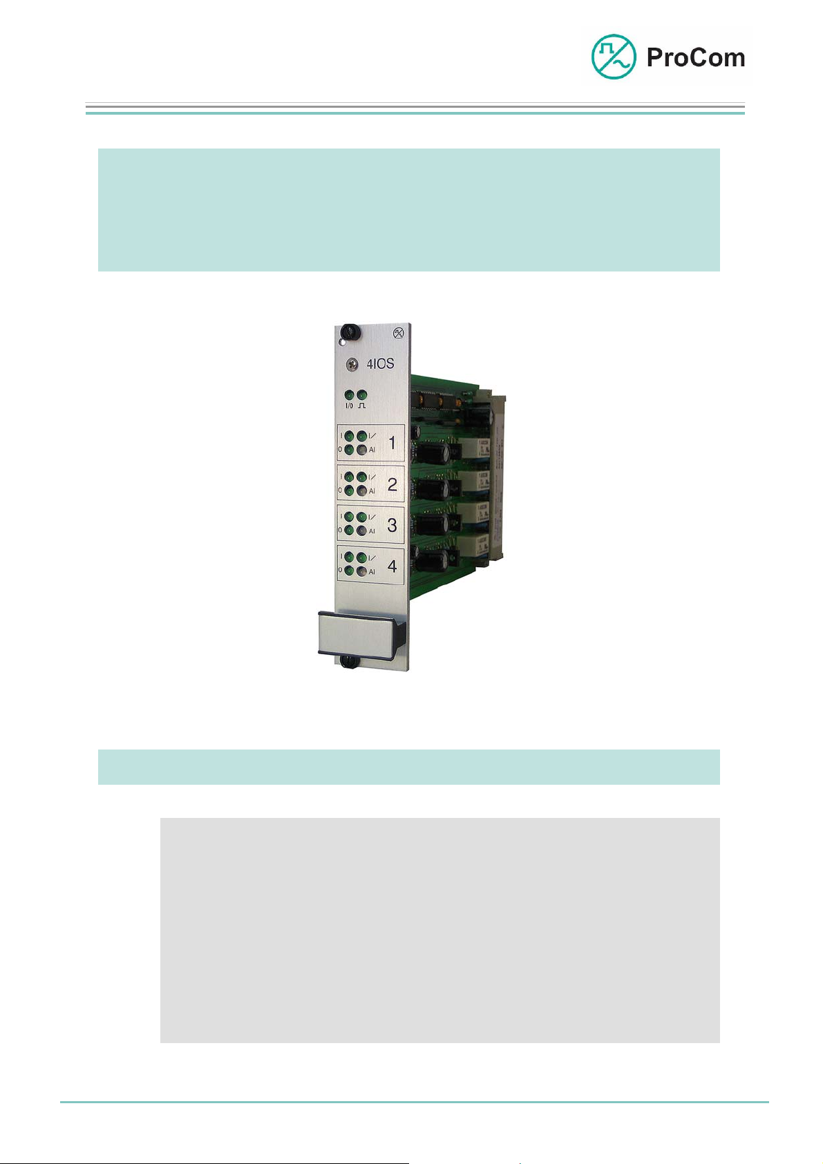
4IOS
Multifunction Module with 4 Relay Outputs and 8 Opto-
coupler Inputs
At a Glance:
• 4 relay outputs with floating switch contacts for
• 8 opto-coupler inputs with secured status transmission
• To generate voice acknowledgements
Fig. 4IOS (L- No. 2.804)
- Remote operation and control functions
- Distribution of loudspeaker circuits
- For diverse signals
- To monitor the status of systems
Date: 13.03.2009 Page:
1/8
© 2008 ProCom, All rights and technical changes reserved
Author: HS Document-No.:
DB_4IOS_2804_01
Page 2
Data Sheet
4IOS
Multifunction I/O Module
The module 4IOS has 4 relay outputs with floating switch contacts, over which
control and remote processes can be triggered as well as loudspeaker circuits
distributed.
The module 4IOS provides interfaces as link between the DVS-21 system and the
outside world. It is able to pass DVS-21 internal statuses as floating signals to the
outside world and non-floating signals from the outside world as floating signals to
the DVS-21 system. For this, eight opto-coupler inputs and four relay outputs can
be used.
The 4IOS module has four independent identical sets.
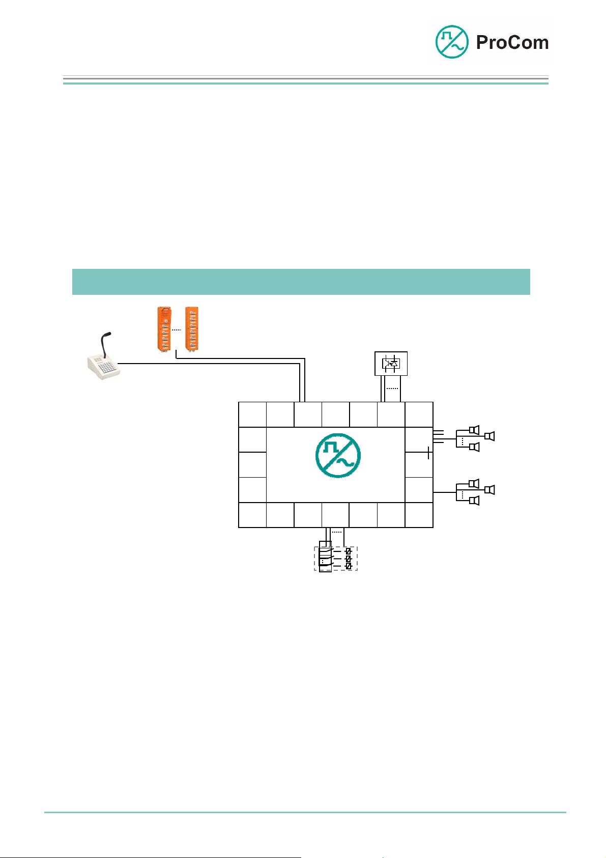
Application Description:
WPS-04
WPS-08
4IOS
Signal Inputs
LK2 .. 5
4IOS
V100
LK1
V100
V100
Havarie
LS 1
LS 2
LS n
Loudspeaker
Distribution
LS 1
LS 2
LS n
DTA-012 030/ 048/ 066/ 084/ 114
2DA
CPU1 4NSASV01
Remote
Operation /
Control /
Monitoring
Input 1 .. 8
DVS-21
4IOS
.
.
.
Application example for the 4IOS with PA and intercom systems
The 4IOS module can be used in various applications and includes the following
functions:
1. In PA systems the function “Distribute Loudspeaker Circuit” [LK-
Aufteilung]
In this function the relay output can be monitored with an optocoupler in respect to voice output.
2. In PA and intercom systems the function “Floating Signal or Control
Outputs” [potentialfreie Melde- oder Steuer- Ausgänge]
In the case of transmissions over several systems, the mode of operation, “Secure Transmission” [Gesicherte Übertragung] can be ac-
Date: 13.03.2009 Page:
2/8
© 2008 ProCom, All rights and technical changes reserved
Author: HS Document-No.:
DB_4IOS_2804_01
Page 3
Data Sheet
4IOS
Multifunction I/O Module
tivated; this means that an appropriate signal will be outputted when
an error occurs.
3. In PA and intercom systems the function e.g. “Alarm input” [Alar-
meingang]
(also binary coded)
These are configured through available programmes in the firmware ICS or specified modes of operation.
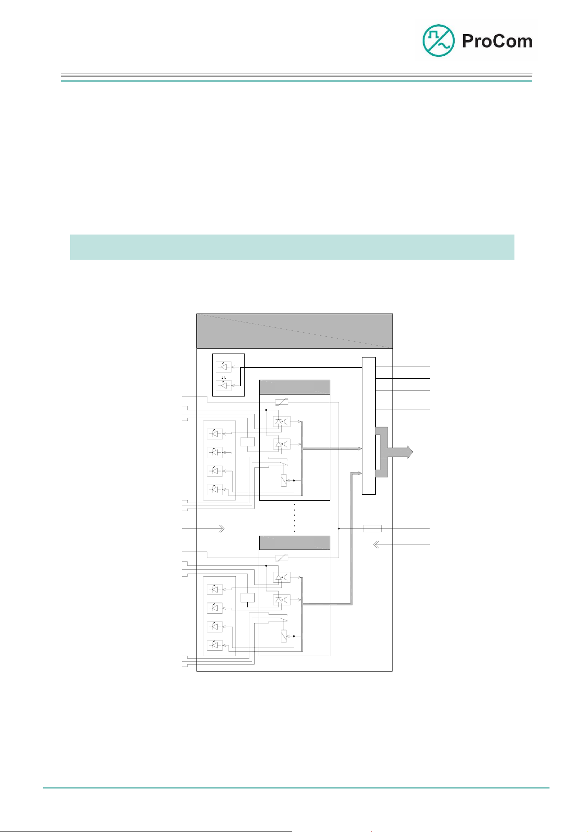
Function Description:
The principle functions are illustrated in the following block diagram.
-48V
-OK
OK
OK'
O
Al
ak
mk
rk
0V 0V
-48V
-OK
OK
OK'
I/
O
4IOS
I/O
S
C
Satz 1
Set 1
I
U>12V
I/
I
t>x
U>12V
t>x
Satz 4
Set 4
t
O
e
u
N
e
T
r
R
P
u
C
O
M
n
L
g
0V
+5V
GND
-5V
KS
BUS
-48V
+0V
ak
mk
rk
The 4IOS consists essentially of a control unit and the 4 independent sets.
Each set is equipped with a relay and 2 opto-couplers.
The relay makes available a floating switch contact.
Date: 13.03.2009 Page:
3/8
© 2008 ProCom, All rights and technical changes reserved
Al
Block diagram 4IOS
Author: HS Document-No.:
DB_4IOS_2804_01
Page 4

Data Sheet
4IOS
Multifunction I/O Module
The two opto-couplers have a common “minus” connection.
The first opto-coupler takes directly the “plus” of its input in a currentlimiting way; for the second the input voltage is also debounced (a few
ms). Besides this a switch threshold of approx. 5 V is specified through a
Zener diode.
This input is used as a rule for low frequency (LF) monitoring.
To realize diverse tasks, switching can be done into 5 different modes of operation per functional group (set), with the help of the ICS software.
“Standard” Operating Mode
In the mode of operation “Standard” all I/O channels are freely configurable
through the ICS software and independent of one another. Here relay outputs
are switched or opto-coupler inputs queried through sending and receiving of
DVS-21 line frames.
Modes of Operation for Secured Status Transmission
- Secure Sender
- Secure Receiver:
- Secure Receiver (inv.)
If transmission of status information over several systems requires additional
security for the internal DVS-21 hardware and data transmission data link layer
then 2 units of 4IOS groups (sets) can be coupled together. In this way an additional data link layer is established between the two sets in which security related statuses can be received, transmitted and outputted again.
For this the mode of operation “Secure Sender” is assigned to the source and
the mode of operation “Secure Receiver” to the target, or in the case of low activity output, the mode of operation “Secure Receiver (inv.)”.
The secure sender transmits in cyclical intervals (times can be configured in the
ICS software) two further verification elements (line frames) in addition to the actual status information.
If, in the case of error, the verification elements do not arrive at the target then
when a configurable time expires the status output including the last status are
frozen and a line error is signalled.
If the verification elements are properly received at the target, but the status information not verified, then every time the verification elements are received a
transmission error will be signalled.
Only after proper reception as well as verification of the verification elements
and status information will the error signals be reset.
Only verified status information will be outputted.
Date: 13.03.2009 Page:
4/8
© 2008 ProCom, All rights and technical changes reserved
Author: HS Document-No.:
DB_4IOS_2804_01
Page 5

Data Sheet
4IOS
Multifunction I/O Module
Sending and receiving of verification elements is indicated through one or two
green blinks of the two-colour LED. This serves as quick confirmation for sender
and receiver.
In the modes of operation for secure status transmission no changes can be
made on the two-colour LED through programming. It is used exclusively for internal purposes. All other I/O channels are fully available, in as far as they are
not in use here.
Operating Mode “Voice Acknowledgement”
In the operating mode “Voice Acknowledgement” the existing relay can be
used as loudspeaker circuit relay and switched using the line frame Li 03
ON/OFF. Through additionally cutting in with the
100 V LF source, a
ON/OFF from 4IOS module) can be generated.
An upcoming LF signal is signalled by the I/LED on the front plate. A positive
voice acknowledgement is generated (sending of the line frame Li 02 ON) and
signalled when the LF level is sufficient.
A generated positive public address acknowledgement is only reset when the
public address is switched off or by cutting in with a new public address with
higher priority.
By sending the line frame Li 08 ON/OFF to the 4IOS module the relay can be
switched without generating a public address acknowledgement.
In the mode of operation “Voice Acknowledgement” the opto-coupler 1 can be
freely used for other functions. Care must be taken, however, that both optocouplers have a common earthing point.
voice acknowledgement (sending of the line frame Li 02
debounced opto-coupler on a
Date: 13.03.2009 Page:
5/8
© 2008 ProCom, All rights and technical changes reserved
Author: HS Document-No.:
DB_4IOS_2804_01
Page 6

Data Sheet
4IOS
Multifunction I/O Module
The Front Plate Symbols and their Meaning:
The System Blinker
Addressing from processor follows
I/O Input/Output
BUS output works as push-push operation with the system
blinker
BUS input works as push-pull operation with the system blinker
I Opto-coupler 1, Not Debounced (depending on set)
Refer to the table below for more information
I/ Opto-coupler 2, Debounced (depending on set)
Refer to the table below for more information
0 Status Display of the Relay (depending on set)
Refer to the table below for more information
Al Status Display of the Transmission, Two-colour
(depending on set)
Refer to the table below for more information
(not freely programmable)
Date: 13.03.2009 Page:
6/8
© 2008 ProCom, All rights and technical changes reserved
Author: HS Document-No.:
DB_4IOS_2804_01
Page 7

Data Sheet
4IOS
Multifunction I/O Module
LED Displays (depending on the set):
Operating Mode LED / Behaviour Meaning
“Standard” and
“Secure”
“Standard” and
“Secure”
“Standard” and
“Secure”
“Standard” Al illuminated red Line 4 being received
“Standard” Al illuminated
“Secure Sender” Al brief double
“Secure Sender” Al brief single
“Secure Receiver”
“Secure Receiver”
“Secure Receiver, inv.”
“Secure Receiver, inv.”
“Voice Acknowledgement”
“Voice Acknowledgement”
“Voice Acknowledgement”
I illuminated Signal to opto-coupler input 1
I/ illuminated Signal to opto-coupler input 2
0 illuminated Relay output switched
green
blinking green
blinking green
Al brief double
blinking green
Al brief single
blinking green
Al brief double
blinking green
Al brief single
blinking green
I illuminated Signal to opto-coupler input 1
I/ illuminated LF (100 V) to opto-coupler input
0 illuminated Relay switched
Line 5 being received
Sending of both verification elements
Sending of one verification element
Receiving of both verification
elements
Receiving of one verification element
Receiving of both verification
elements
Receiving of one verification element
2
Date: 13.03.2009 Page:
7/8
© 2008 ProCom, All rights and technical changes reserved
Author: HS Document-No.:
DB_4IOS_2804_01
Page 8

Data Sheet
4IOS
Multifunction I/O Module
Technical Data:
Operating Voltage: +/-5 V (control)
Operating Voltage: 48 V
Operational Current (+ 5V): Max. 84 mA, 5 mA idle (relay
current)
Operational Current (-5 V): Max. 70 mA, 0 mA idle (relay
current)
Operational Current (48 V): Max. 64 mA (opto-coupler )
Interfaces: 4 x 2 opto-couplers each with 1 debounced,
24 - 60 V operating voltage
4 x relay switch contact, max. 1 A
4 x -48 V fused voltage
Weight: 170 g
Installation Height: 3HE
Installation Width: 6TE
Date: 13.03.2009 Page:
8/8
© 2008 ProCom, All rights and technical changes reserved
Author: HS Document-No.:
DB_4IOS_2804_01
 Loading...