

Page 1
Data Sheet
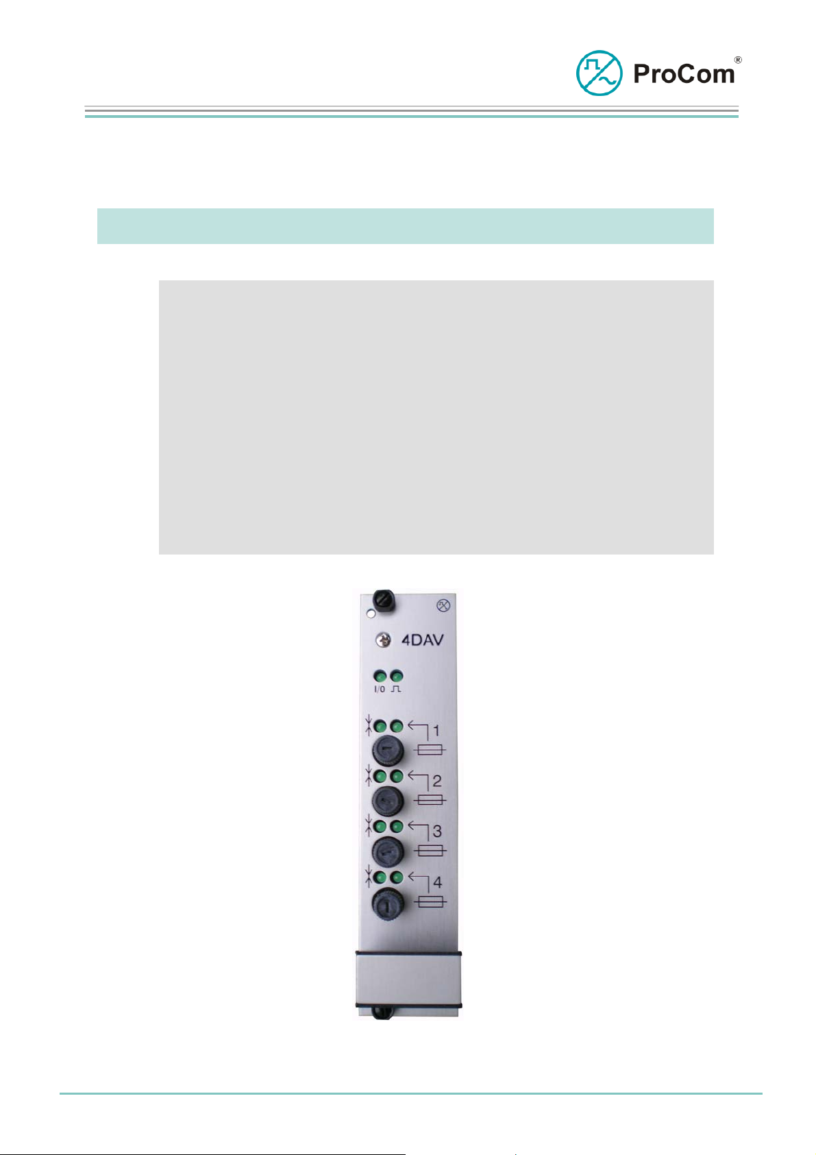
4 DAV
Line card for 4 digital stations in 2 wire technique
The audio frequency (AF) interface module is designed for the switching on of 4 call
stations in two-wire technology.
At a Glance:
• Digital robust transmission in two-wire technology
• Switching-on of up to four call stations
• Call station monitoring from the control unit
• Monitoring of call station voltage
• AF monitoring function (option)
• Establishing long-distance lines
• Sending/receiving level can be regulated
Fig. 4DAV (L- No. 2.302)
Date:
21.04.2010
Page:
1/5
© 2008 ProCom, All rights and technical changes reserved
Author:
NB
Document-No.:
DB_4DAV_ 2302_02
Page 2
Data Sheet
4 DAV
Line card for 4 digital stations in 2 wire technique
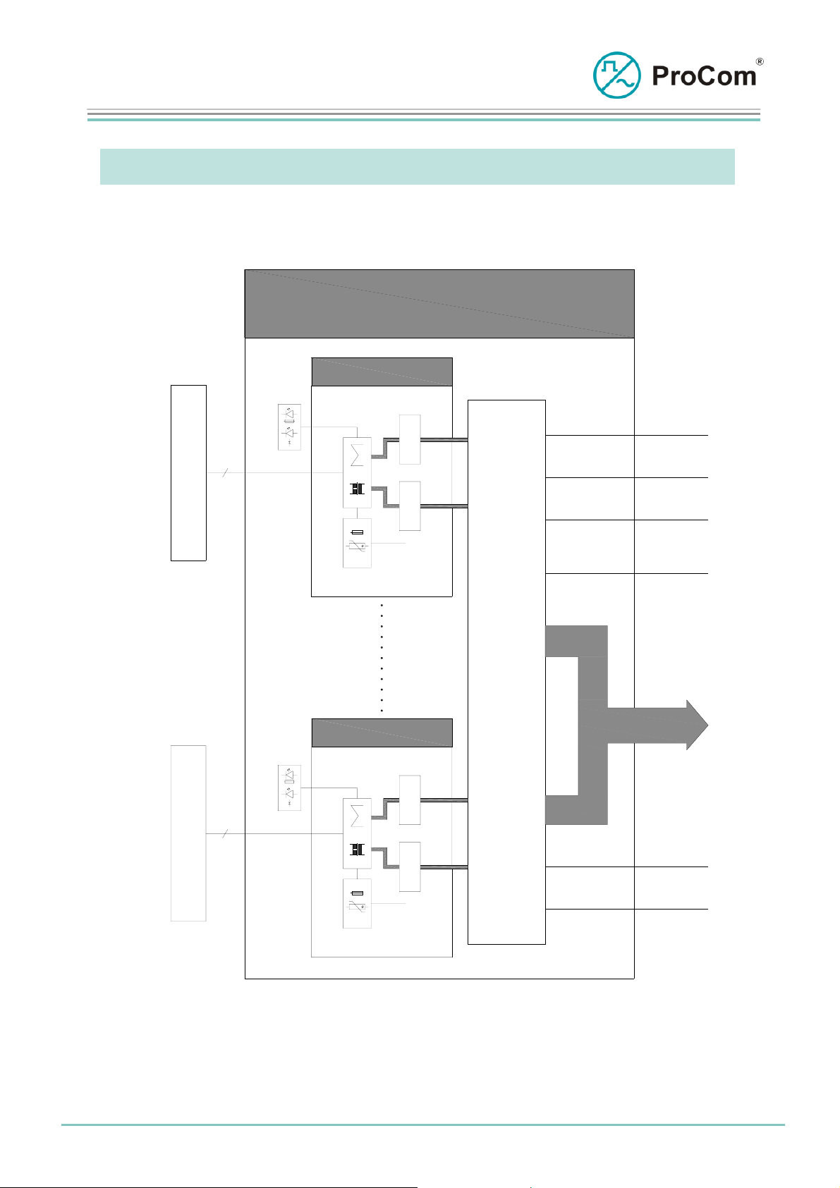
Functional description:
The principle functions of the 4DAV:
4DAV
Set 1
LED
C
a
l
l
2
S
t
a
t
i
o
n
Indication
M
O
D
E
M
C
O
D
E
C
PTC
-48V
C
+5V
GND
-5V
KS
O
N
T
R
Set 4
LED
C
a
l
l
2
S
t
a
t
i
o
n
Indication
M
O
D
E
M
C
O
D
E
C
PTC
-48V
O
L
BUS
-48V
+0V
Block diagram 4DAV
The 4DAV has four independent sets. One call station with one pair of wires can be
connected to each set.
Date:
21.04.2010
Page:
2/5
© 2008 ProCom, All rights and technical changes reserved
Author:
NB
Document-No.:
DB_4DAV_ 2302_02
Page 3

Data Sheet
4 DAV
Line card for 4 digital stations in 2 wire technique
If the 25 W booster amplifier of a call station is activated or connected then additional
power feeding is necessary. This can be done by two additional wires or by local
feeding.
Each 4DAV line is secured both by a PTC and a fuse on the front panel. By spending
an additional pair of wires, an additional call station amplifier can be fed in with 48V.
This additional pair of wires is fused additionally on the circuit board.
When releasing one of the fuses, a message will be sent towards CPU1 module. The
“fuse” LED at the front panel will then show a typical blinking behaviour (see chapter
“Symbols on the Front Panel”).
The functionality of the AF module can be programmed per set using the
configuration software ICS. Control frames are sent bi-directional over the modem
line cyclically between the 4DAV set and a call station (for example WPS-08, Ex).
If a subscriber (call station) is absent then an error frame is sent to the CPU and
sending / receiving LED is blinking slowly.
This monitoring function can be disabled with the ICS.
This line card is suitable for fire protection system with application microphone
monitoring system according to DIN EN 60849 (VPE0828).
Following audio bandwidths are selectable dynamically:
- 3,5 kHz
- 7 kHz
The mode of operation is set in the configuration software ICS:
- Call station operation mode: One call station is expected as subscriber
- Master operation mode: As counterpart a 4DAV as slave is expected
- Slave operation mode: As counterpart a 4DAV as master is
expected
- No modem operation mode: The 4DAV only transmits AF signals
For this an audio signal is generated cyclically over the microphone of the call station
and sent to the 4DAV. If the transmission of the AF signal fails, then an error
message is generated.
This mode is activated by ticking the option in ICS.
Date:
21.04.2010
Page:
3/5
© 2008 ProCom, All rights and technical changes reserved
Author:
NB
Document-No.:
DB_4DAV_ 2302_02
Page 4

Data Sheet
4 DAV
Line card for 4 digital stations in 2 wire technique
The Symbols on the Front Panel and their Meaning:
I/O Input/Output
Sending/Receiving (depending on the set)
LED lit: 4DAV sending to subscriber
LED blinking: 4DAV receiving from subscriber
LED blinking slowly: modem connection disrupted
The System Blinker
Addressing from processor taking place
BUS output works as push-push operation with the system blinker
BUS input works as push-pull operation with the system blinker
Fuses (depending on set)
LED on: Both fuses OK
LED flashing 1x: 2-wire fuse (front panel) defect
LED flashing 2x: 4-wire fuse (circuit board) defect
LED flashing 3x: Both fuses defect
Date:
21.04.2010
Page:
4/5
© 2008 ProCom, All rights and technical changes reserved
Author:
NB
Document-No.:
DB_4DAV_ 2302_02
Page 5

Data Sheet
4 DAV
Line card for 4 digital stations in 2 wire technique
Technical Data:
Operating Voltage: +/-5 V (control)
Operational Current (+5 V): 200 mA
Operational Current (-5 V): 4 mA
Temperature Range: 0° C to 45 °C
Bandwidth: 3,5 kHz / 7kHz
Range: typ. 3 km by 0,8mm 2-wire connection
(without additional amplifier)
Range: typ. 3 km by 0,8mm 4-wire connection
(with an additional amplifier)
Weight: 300 g
Installation Height: 3HE
Installation Width: 6TE
Date:
21.04.2010
Page:
5/5
© 2008 ProCom, All rights and technical changes reserved
Author:
NB
Document-No.:
DB_4DAV_ 2302_02
 Loading...