

Page 1
Data Sheet
24LI
24 Line Module
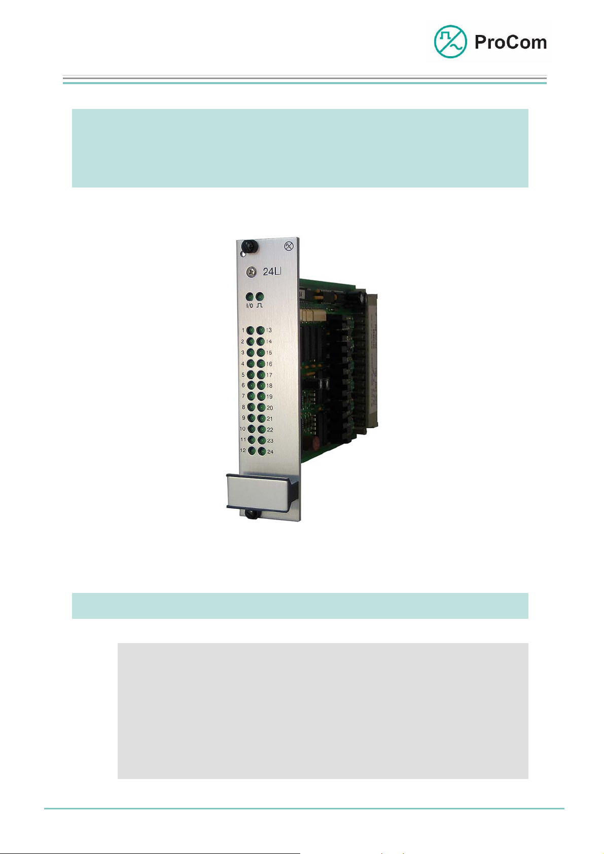
24LI
24 Line Module for Expanded Control Functions
At a Glance:
Date: 25.03.2009 Page:
• Control function for a total of 24 keys of call stations in line
technology
• Control functions and acknowledgements of command
signalling systems (PABX)
• Control functions for e.g. card racks
1/4
© 2008 ProCom, All rights and technical changes reserved
Fig. 24LI (L- No. 2.824)
Author: HS Document-No.:
DB_24LI_2824_01
Page 2
Data Sheet
A
A
V
24LI
24 Line Module
The DVS-21 is capable of connecting not just our own but also third-party devices. The module 4NPA makes possible an LF (low frequency) connection and
control over the C and V point of four devices.
In order to meet other control requirements the line module 24LI is additionally
required.
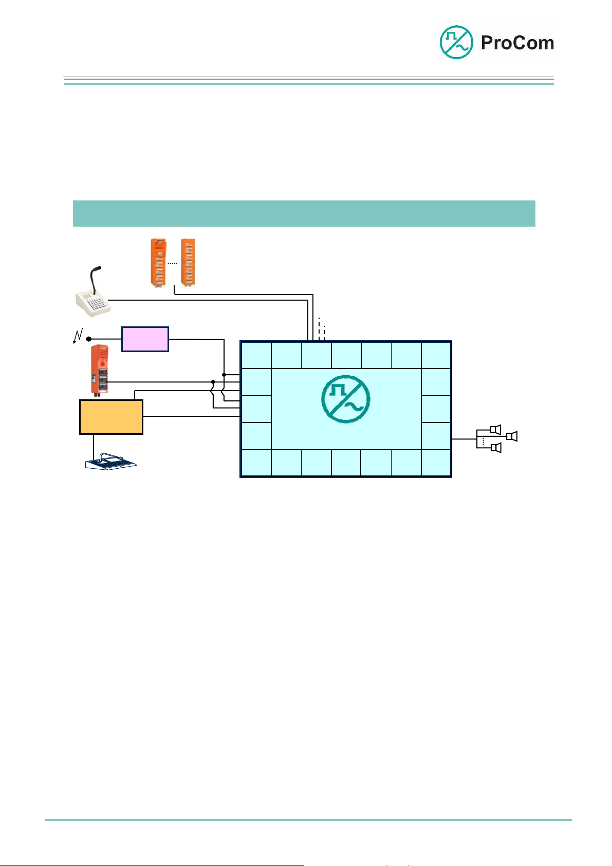
Application Description:
WPS-04
WPS-08
DTA-012 030/ 048/ 066/ 084/ 114
Radio
PABX
Card rack
Third-party Call Station
PA /
Control / ACK
intercom
Radio
LF a / b
AWC-06
LF a / b
Carrier
Monitoring /
Tone ringing
SV01
4NP
24LI
2DA
CPU1 4NS
DVS-21
100
LC
LS 1
LS n
Application example for the 24LI with PA and intercom systems
The line module 24LI manages various control functions when using one or more
4NPA modules.
The individual lines are independent of one another. If, for example, third-party
devices are connected with line technology, a key/button is required for each line,
which means e.g. with a 24LI-module four call stations each with three double
toggles can be switched in.
More about the various applications can be found in the data sheet for the 4NPA
module.
LS 2
Date: 25.03.2009 Page:
2/4
Author: HS Document-No.:
© 2008 ProCom, All rights and technical changes reserved
DB_24LI_2824_01
Page 3

Data Sheet
r
24LI
24 Line Module
Function Description:
The principle functions are illustrated in the following block diagram.
24LI
Linie 01
Line 01
Linie 02
Line 02
Linie 24
Line n
Anzeige
Indication
System-
System-
blinke
blinker
I/O
I/O
Linie 01
Line 01
Linie 02
Line 02
Linie 24
Line 24
+0V
+0V
+0V
+5V
S
C
t
O
e
N
u
e
T
r
R
P
u
C
O
M
n
L
g
Output
Output
01
MUX
02
3x8 channel
3 x 8 - Kanal
24
Input
Intput
5V
01
5V
MUX
02
3 x 8 - Kanal
5V
3x8 channel
24
GND
-5V
KS
BUS
-48V
+0V
Block diagram 24LI
The 24LI has 24 independent bi-directional inputs/outputs.
These lines are configured using the ICS software.
Input and output status is displayed for each line by an LED on the front plate.
The reference potential is earth or 0 V.
The output idle voltage of the lines corresponds to the system operating voltage,
i.e. type -48 V.
-24 V (optional) to a max. -60 V can be switched in.
An active line puts through 0 V as output or is 0 V as input.
The line current is a maximum of 150 mA. The line is switched off in the case of
excessive load.
Date: 25.03.2009 Page:
3/4
Author: HS Document-No.:
© 2008 ProCom, All rights and technical changes reserved
DB_24LI_2824_01
Page 4

Data Sheet
p
r
24LI
24 Line Module
The Front Panel Symbols and their Meaning:
The System Blinker
Addressing from processor taking place
I/O Input/Output
BUS output works as push-push operation with the systemblinker
BUS in
1 ⋅⋅⋅ 24 Send/ Receive Status (depending on set)
LED blinks: LF signal being sent
LED lit: LF signal being received
Technical Data:
Operating Voltage: +/-5 V (control)
Line Output: 0 V/-48 V (control)
Line Input: 0 V/-48 V
Line Current: Max. 150 mA
Temperature Range: 0 °C to 45 °C
Weight: 300 g
Installation Height: 3HE
Installation Width: 6TE
ut works as push-pull operation with the system blinke
Date: 25.03.2009 Page:
4/4
Author: HS Document-No.:
© 2008 ProCom, All rights and technical changes reserved
DB_24LI_2824_01
 Loading...