

Process Technology DLC16, T-DLC16 User Manual
DLC16 / T-DLC16
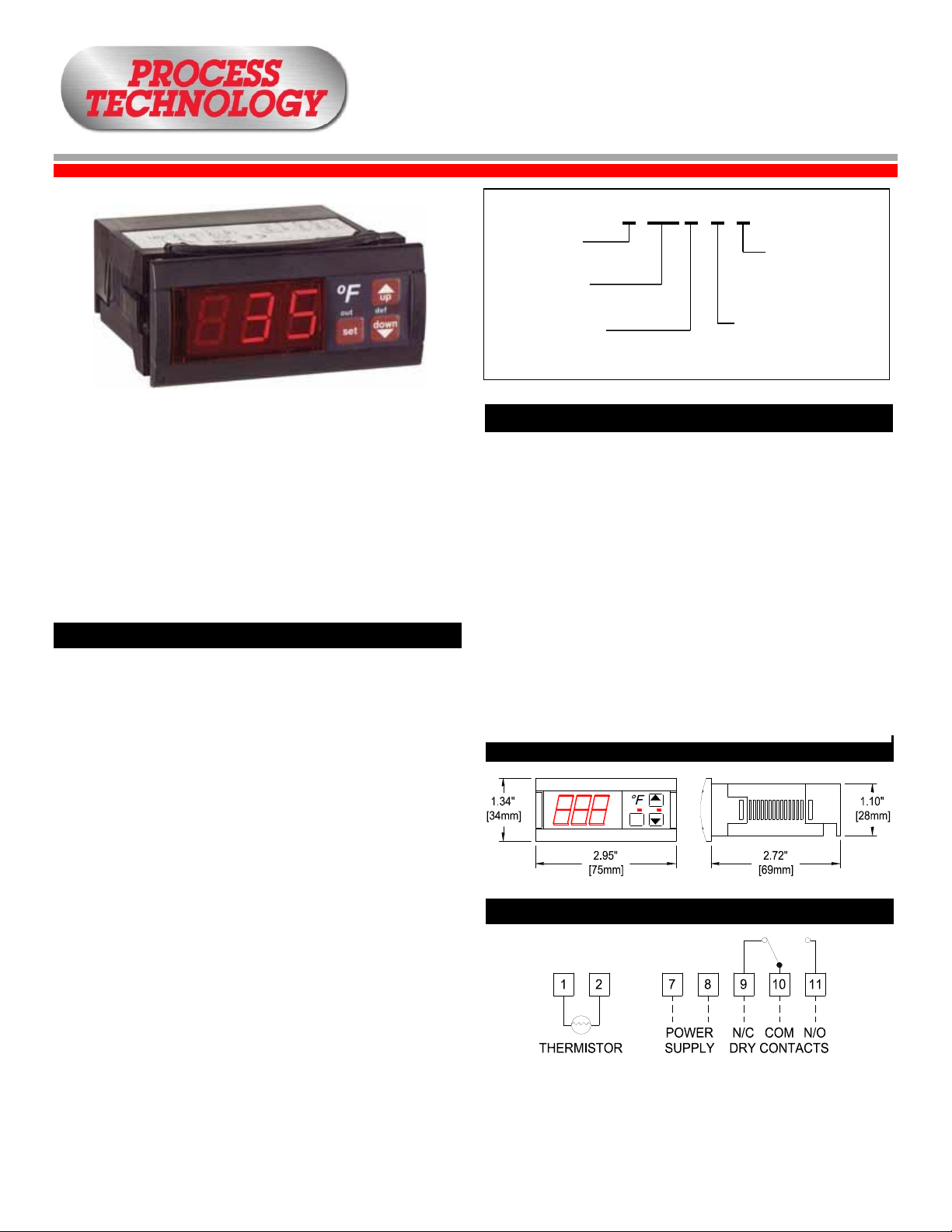
Dimensions
Specifications
Probe Range:
-58°F to 302°F (-50°C to 150°C)
Input:
1.5-inch (4 cm) thermistor (1000Ω @
25°C) with 10-foot (3-meter) cable
Accuracy:
±1°
Resolution:
±1 digit
Output:
16 amp SPDT relay @ 250 VAC
Horsepower Rating:
3/4 HP
Supply Voltage:
120VAC or 240VAC
Supply Power:
4 VA (230V)
Ambient Temp:
14°F to 158°F (-10°C to 70°C)
Storage Temperature:
-4°F to 176°F (-20°C to 80°C)
Front Panel Protection:
IP64
Display:
RED, 3-Digit LED
The DLC Digital Temperature Switch is a compact, easy to
program temperature controller.
3-digit LED screen displays probe temperature
error or alarm messaging
available in 120VAC or 240VAC
non-volatile memory storage
includes a thermistor with 10ft cable and fitting clips for
panel mounting
Installation
Figure 2: DLC Wiring
Wiring Diagram
up
defout
down
set
T - DLC16 – 1 - C
Figure 1: Model Number Description
Thermostat
Only
Series DLC
Amperes
(16 Amps)
Voltage
1 = 120VAC
2 = 240VAC
Celcius Display
(Optional)
Digital Temperature Switch
Note: Mount DLC away from vibration, impacts, water and
1. Locate appropriate installation site.
2. Cut hole in panel 2.80 x 1.14 inches (71 x 29 mm).
3. Apply silicone (or rubber gasket) around the perimeter of
4. Insert the T-DLC into hole in the panel.
5. Slide removable fitting clips onto the T-DLC from the
6. Remove the back cover to wire the T-DLC (see Figure 2,
7. Replace cover once wiring is completed.
Note: Probe cable length must not exceed 328 ft (100 m).
corrosive gases.
the hole to prevent leakage.
back to secure to panel.
T-DLC wiring).
Do not install probe cable near power cables.
M-33-02 T-DLC16 Manual
Revision – Date: 03 – 03/30/2016 1

Parameter Programming
Parameters
Parameter Descriptions
LED Indications
Display Messages
Maintenance
Description Units Range
SP
Set Point Degrees r1 to r2
r0
Differential or Hysteresis Degrees 1 to 20
r1
Lower Value Set Point Degrees -50 to 150°
r2
Higher Value Set Point Degrees -50 to 302°
d0
Heating or Cooling Control Option Ht/Co
d2
Time for Defrosting Minutes 0 to 59 min.
d8
Interval Time between
defrosting
Hours 1 to 24 hr.
c0
Min. Stop Time for Load Minutes 0 to 59 min.
c1
Continuous Cycle Time Hours 0 to 24 hr.
c2
ON time of fault cycle Minutes 0 to 999 min.
c3
OFF time of fault cycle Minutes 0 to 999 min.
P1
Ambient Probe Adjustment Degrees -10 to 10
H5
Parameter Access Code Numeric 0 to 99
t0
Max. Temp. on Display Degrees -50 to 302°
Access set point (SP) without code protection
Press SET. SP text will appear on the display.
Press SET again. The real value is shown on the display.
The value can be modified with the UP and DOWN arrows.
Press SET to enter any new values.
Press SET and DOWN at the same time to quit programming
or wait one minute and the display will automatically exit
programming mode.
Access to all code protected parameters
Press SET for 8 seconds. The access code value 0 is shown
on the display. (Unit comes with code set at 0 from factory*).
With the UP and DOWN arrows, code can be set to user
needs.
Press SET to enter the code. If it is correct, the first parameter
label is shown on the display (SP).
Move to the desired parameter with the UP and DOWN keys.
SP = Set Point - Desired Regulation Temperature.
r0 = Differential or Hysteresis.
r1 = Lower Set Point Limit.
r2 = Higher Set Point Limit.
d0 = Heating or Cooling Control - This control only does
regulation cycles. Neither defrosting nor continuous
cycles exist.
Heating: To choose Heating Control - Set d0=Ht
(The load is connected when TS<SP-r0.
The load is disconnected when TS>=SP.)
Cooling: To choose Cooling Control - Set d0=Co
(The load is connected when TS>=SP+r0.
The load is disconnected when TS<=SP.)
(TS = Temperature of ambient probe)
d2 = Duration of Defrosting Time (The value programmed from
the factory is d2=15 minutes. [Ht-defrosting will never
start, if Co=0, defrosting will never start.])
d8 = Interval time between defrosting.
c0 = Minimum time between start and stop.
c1 = Continuous cycle time.
c2 = ON time of fault cycle, when ambient probe broken
c3 = OFF time of fault cycle, when ambient probe broken
P1 = Ambient Probe Calibration. (Offset degrees to adjust
ambient probe. If the probe is not placed in the exact
point that is to be measured, use a standard thermometer
and adjust the difference in this parameter).
H5 = Access to probe parameters. (This code is set to 0 from
the factory).
t0 = Maximum temperature on display. (Temperature limit for
defrosting).
7010 Lindsay Dr. • Mentor, OH 44060 U.S.A. • US/CN: 800-621-1998 • 440-974-1300 • Fax: 440-974-9561
• E-mail: info@process-technology.com
Press SET to view the value on the display.
The value can be modified with the UP and DOWN arrows.
Press SET to enter the value and exit to test parameter.
Press SET and DOWN at the same time to quit programming
or wait one minute and the display will automatically exit
programming mode.
* The access code can be reset to 0 by turning off the
controller and turning it on again while keeping the SET key
pressed.
OUT This indicates the load is connected. The system waits for
the programmed minimum stop time of the load.
Def This indicates defrosting is activated.
In normal operation, the probe temperature will be shown on the
display. In case of alarm or error, the following messages will be
shown:
ER = Memory Error
--/--- = Short-Circuit Probe Error
oo/ooo = Open Probe Error
After final installation of the DLC Series Digital Temperature
Switch, no routine maintenance or calibration is required. A
periodic check of temperature accuracy is recommended. If the
control is not reading accurately but the error is linear, use the
ambient probe adjustment parameter (P1) to compensate for the
difference.
M-33-02 DLC16 / T-DLC16 Manual
Revision – Date: 03 – 03/30/2016 2
 Loading...