

Page 1
Specifications .................................................................. 1
DE20 / T-DE20 Instruction Manual
TABLE OF CONTEN
TS
DE20 / T-DE20 Digital Temperature
General Description ............................................................................ 2
Installation Procedure ......................................................................... 2
Overtemperature Protection .............................................................. 3
Set Point & Features ........................................................................... 4
Alarm Feature ...................................................................................... 4
Error Conditions ................................................................................... 4
Error Messages ................................................................................... 4
Power and Relay Wiring .................................................................... 5
Calibration ............................................................................................. 6
2 Wire RTD Sensor Calibration ........................................................ 6
Resistance Signal Calibration ........................................................... 7
3 Wire RTD Calibration ...................................................................... 7
Thermocouple Calibration ................................................................. 8
Voltage Signal Calibration .................................................................. 8
Current Input Calibration ................................................................. 10
Frequency Signal Calibration ......................................................... 10
Configuration (Setup) ....................................................................... 11
Main Menu Summary...................................................................... 11
Sensor Type (U1) ............................................................................. 12
Signal Offset (U2) ............................................................................. 12
Signal Filter Setting (U4) .................................................................. 12
Set Point Dead Band (U5) .............................................................. 13
Display Stabilizer (U8) ...................................................................... 13
Set Point Limit (L) .............................................................................. 13
Heating or Cooling Switch (F2) ...................................................... 13
Alarm On/Off Switch (F3) ................................................................ 14
Unit Display Enable (F4) ................................................................. 14
Temperature Units Conversion (F5) ............................................. 14
Sensor DIP Switch Settings ........................................................... 14
Electrical Noise and Interference ................................................... 15
Illustration of a Typical Heater
Installation in a Process Tank ......................................................... 15
7010 Lindsay Drive • Mentor, Ohio 44060 • Phone: 440-974-1300
USA/CN: 800-621-1998 • Fax: 440-974-9561 • www
.processtechnolog
COPYRIGHT 2016 Process Technology
y.com
Page 2
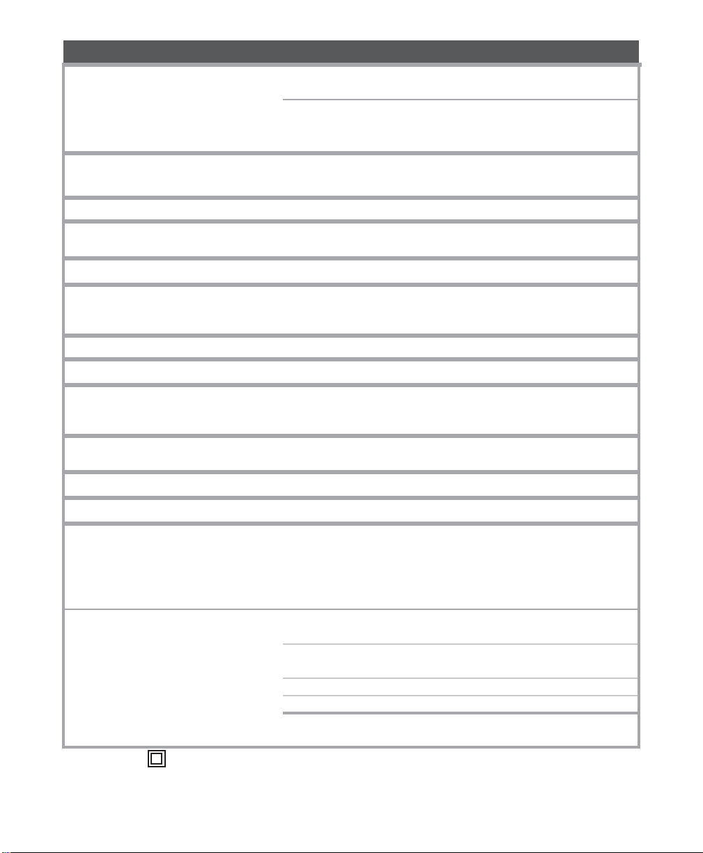
DE20 Specifications
Standard Input
2 wire1000 ohm RTD TCR (alpha),
0.00385 ohm/ohm/°C
RTD Self Heating Coefficient:
5° C/w in 0.2 m/s water; 200° C/w in
1 m/s air measurement current, 0.1 to 0.2 mA
Input Range
-40°F (-40°C) to 1000°F (538°C)
°F or °C field selectable
Set Point Range
Selectable throughout the input range
Sensor Break or
Short Protection
De-energize control output (No sensor short
protection with Thermocouple sensor)
Accuracy
± 0.25% span, ± 1 digit
Enclosure
Type 12, IP54
Face suitable for panel mounting
(#20 ga. through 1/4 thick panels)
Display
4 digit, (1/2" nominal), LED display screen
Control Function
ON/OFF Electromechanical Relays
Control Outputs
SP1 Set Point
(reverse acting) SPDT 20A resistive@240 VAC max
1HP@240 VAC max, 1/2 HP@120VAC
ON/OFF Differential
Field adjustable
1° (F or C) to 99°
Memory
Nonvolatile
Supply Voltage
Operating Conditions
• Indoor Use Only
• 20°F (-7°C) to 130°F (54°C)
• Max Altitude: 3000m
• Max Relative Humidity: 80%
• Pollution Degree 2
• Installation Category II
Input Options
RTD 2 & 3-wire 100 ohm 0.00385 ohm/ohm/ºC or
0.00392 ohm/ohm/ºC
Thermocouples - (types J, K, T, R)
NIST Monograph 175, revision ITS-90 (Obsolete)
Current 4-20mA DC
Voltage (1-10 VDC)
Frequency (0-200 Hz, counts/second),
+/- 6 VDC p to p (up to 30VDC peak with Sw2 ON)
100V to 240V +/- 10% VAC, 50-60 Hz, 13VA
M-33-01-05-3/19/18 1 DE20/T-DE20 Manual
Equipment protected throughout by Double Insulation or Reinforced Insulation.
Page 3
General Descriptio
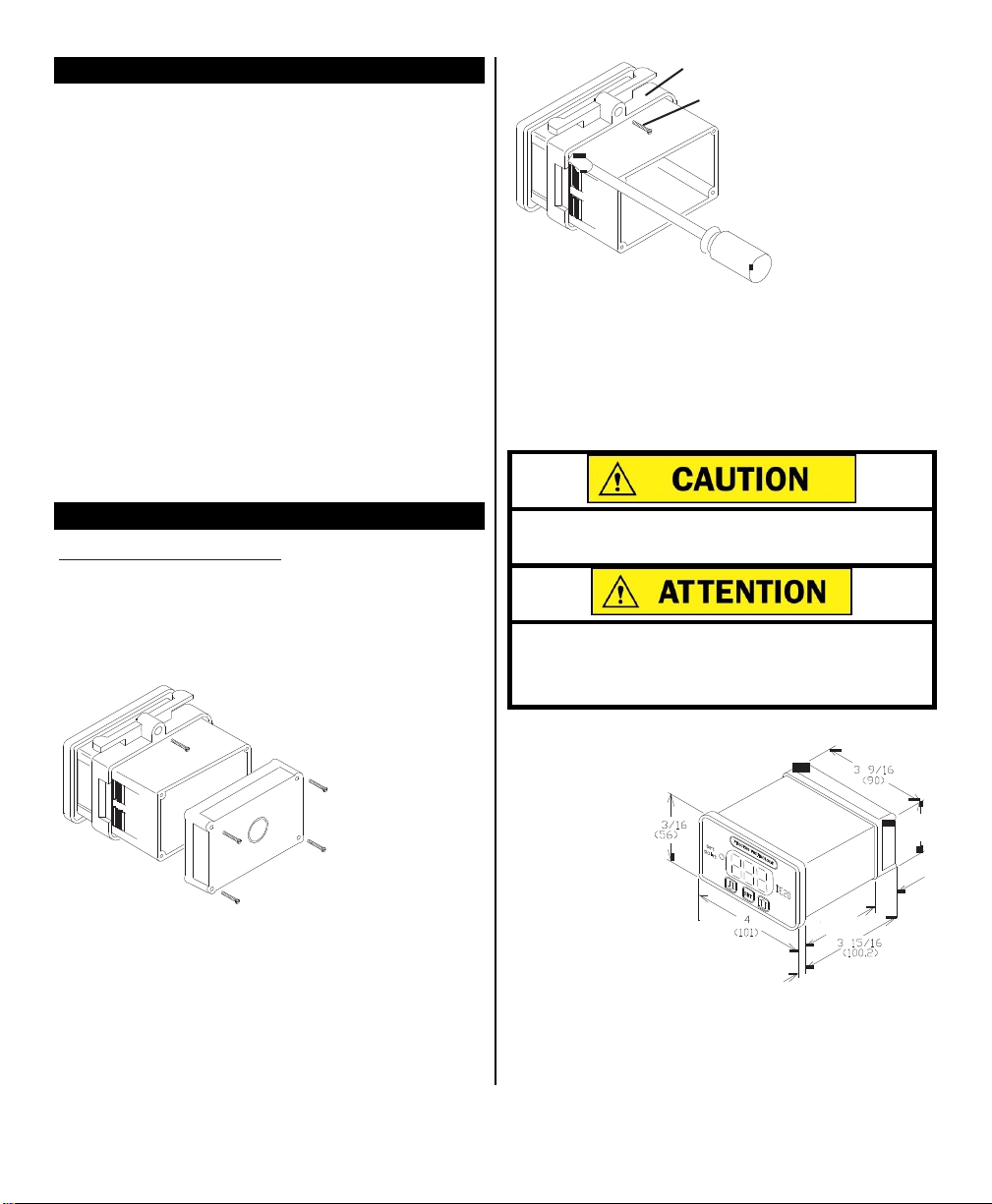
Avoid damaging circuitry. Remove rear cover before removing knockouts with a hammer/punch.
Évitez d'endommager les composants du DE20. Enlevez
le panneau arrière avant d'enlever le plastique pour
faire des trous avec un marteau ou un poinçon.
Retaining collar
Retaining
collar screws
The DE20 digital temperature control is a microprocessor based device that operates one relay. The
relay’s contact state is indicated as SET POINT on the
front panel.
The temperature sensor (i.e. RTD or thermocouple)
sends a signal to the DE20 controller. The DE20 compares this signal to a value, determined by the operator
and set in the control’s memory for the SET POINT. In
the heating mode if the sensor signal is lower than the
set point value, the DE20 energizes the relay and its
isolated contacts close.
The DE20 is also equipped with an “ALARM
CONDITION” feature. This feature is activated by
using the “F3” parameter (described on page 13). The
DE20 enters an “ALARM CONDITION” any time the
sensor signal has exceeded the ALARM SET POINT.
Under this condition, the DE20 de-energizes the relay
and the letters “AAA” flash on the
LED display.
n
Installation Procedure
Suitable for indoor use only.
Unpack and inspect the controller for damage upon
receipt. Any shipping damage claims must be made
through the freight carrier that delivered the controller.
Remove the rear cover and inspect the controller for
internal damage.
Remove the
panel retaining
collar by inserting a flat head
screwdriver
under the collar
on alternating
sides while sliding the collar back.
Cut a 1/8 DIN finished opening: 1.750" x 3.625" (44
mm x 92 mm) in the panel where the DE20 is to be
mounted.
.
Remove the rear
cover. Select
from the four (4)
knockouts on
the rear cover
that which offers
the most convenient routing
for external wiring. Remove the knockouts before reattaching the
rear cover or inserting the control in the panel.
M-33-01-05- 3/19/18
Insert the DE20
through the prepared opening
and slide the
retaining collar
over the case
from the rear of
the panel. After
hand tightening
the collar, tighten
the two (2) collar
screws to ensure a secure
fit.
Install a suitable liquid tight conduit fitting through the
knockout opening following manufacturer’s instructions and install field wiring. Using the wiring diagram
2 DE20/T-DE20 Manual
Page 4
supplied with the controller, install the required input
Overtemperature protection is necessary in
any system where a fault condition could produce a fire or any other hazardous condition.
Operation without thorough safety precautions
can result in equipment failure, property damage and personal injury.
La protection de surchauffe est nécessaire
dans n'importe quel système où une condition
fausse avec résultat d'une temperature haute
pourrait produire une incendie ou autre condition dangereuse. L'opération sans les précautions complètes de sécurité pourrait mener à la
défaillance de l'equipement, l'endommagement
de la propriété, ou des blessures.
and output wires. Use National Electric Code and
local codes for determining wire sizing, insulation,
terminations, etc.
The factory supplied 1000 ohm RTD sensor can be
extended using standard electrical hookup wire (22
awg or larger). The effect of additional 22 awg sensor
wire length on control calibration is approximately 1ºF
for every 65 feet.
Note:
This does not apply to
MUST use specific
ing the sensor wire length. Use of incorrect extension wire can cause hazardous operating
thermocouple wire when
THERMOCOUPLES.
extend-
conditions.
You
Overtemperature Protection
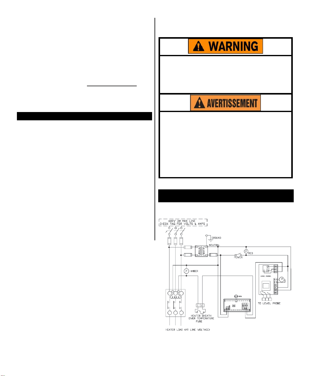
Component failure (sensors, relays, temperature controller, etc.) in a temperature controlled process can
result in damage to the product, heater over temperature, and the possibility of a fire.
To safeguard against these events, install over temperature protection. This will interrupt the heater power
supply in the event of low solution level.
Process Technology heaters include a thermal device
(Protector 1, 2, or 3) on the heater to monitor the heater’s surface temperature. When wired properly, these
devices cut the power to the heater in low solution level
conditions. In addition to thermal protection, Process
Technology requires the use of liquid level controls to
monitor the solution level and shut off the heaters prior
to an overtemperature condition occurring.
Ensure you read and adhere to all Over-temperature
protector installation instructions and warnings.
Overtemperature Protection Device with Low Level
Cutoff Sample Wiring Diagram
(your wiring may differ)
M-33-01-05 - 3/19/18
3 DE20/T-DE20 Manual
Page 5

Set Point and Features
Control Set Point
The set point value will be displayed whenever the
“SET” key is pressed. This value can be changed by
the following procedure:
Note: The units displayed, ºC, ºF, Hz, volts, mA or
ohms are established during the setup of the controller. See F2
set point relay from reverse to direct acting.
Press both the “SET” key and the decrease “” keys
simultaneously and hold for 3 seconds. When released the set point value and a decimal point will
appear, release both keys. Wait approximately one
second, then using the decrease “” key or increase
“” key, adjust the display to your new value. Depress the “SET” key to enter your new value.
Note: If the “SET” key is not pressed within 5 sec-
onds, the new
will revert to its previous setting.
The controller will automatically return to the operating mode and display the current temperature.
instructions
value
will be lo
on page 12 for changing
st and the set
poin
t value
Alarm Feature
Note: This is not a safety device.
The Alarm feature, which is enabled using the “F3”
set-ting during setup (see page 13), allows the
user to establish a set point above which the control
will enter into an alarm condition. This set point
should be higher than the set point setting on the
control. During the alarm condition the control relay
will de-energize the set point relay and flash “AAA”
on the display.
After enabling this feature, you may view and adjust
the “ALARM SET POINT” on the display. The alarm
set point value will be displayed and can be adjusted
by pressing the “SET” key and the increase “” key
simultaneously and holding them for approximately
three seconds. The alarm set point value will appear
as a flashing display.
Note: If the “SET” key is not pressed within 5
sec-
onds, the new
value will revert to its previous setting.
To change the “ALARM
increase “” or decrease “” keys while the display
is flashing. Press the “SET” key to enter your new
value. If you wish to accept the current value, press
the “SET” key.
value
will be lo
SET POINT”,
st and the set
press the
poin
t
Error C
Sensor values that are out of range will generate an
error display. For Celsius: <-40ºC or >+538ºC. For
Fahrenheit: <-40ºF or >+1000ºF.
In the event of an improperly connected RTD sensor
or thermocouple, or if the control reads an “open”
circuit, the message “HHH” is displayed and the control de-energizes the control relay. In the event the
RTD sensor “shorts”, the message “UUU” is displayed
and the control de-energizes the control relay.
Note:
Thermocouple “shorts”
measurement point to be created. This will lead to
false
readings
and
ondition
dangerous operating
s
cause a
new
junction/
conditions.
Error Messages
If the calibration and setup information stored within
the memory becomes corrupt or erased, the control
will switch to its default calibration/configuration settings. The display will flash the letter “c” on the left
side when default values are activated. The physical
size and position of the letter “c” will define the exact
nature of the problem.
Note: Shorted thermocouples will not result in an
error condition. Instead, incorrect readings will be
displayed.
A small “c” in the upper left-hand corner indicates the
control is relying on default (factory set) calibration
values. This happens when the control is new and
has not yet been calibrated (setup).
A small “c” in the lower left-hand corner indicates the
control is relying on default configuration values. This
is a rare condition, but may occur if the control has been
calibrated for use with a two-wire RTD sensor but the
configuration parameters have not been changed from
their default values. Changing any of the configuration
or set point variables will turn off this indication.
A large “C” on the left side of the display indicates the
control is using the default values for the configuration
and the calibration. This can occur in a new control
that has never been calibrated or configured, or in a
control wherein the memory has been erased.
The controller will automatically return to the operating mode and display the current temperature.
M-33-01-05 - 3/19/18
4 DE20/T-DE20 Manual
Page 6
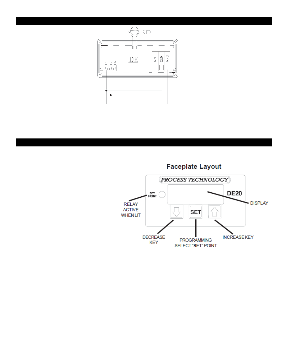
Power, Heating and Cooling Relay Wiring (rear view of controller)
HOT NEUTRAL
POWER SUPPLY
85-265 VAC
50-60 hZ, 13VA
H
EATER, CONTACTOR or
SOLENOID
20 AMPS @ 240 VAC
1 HP @ 240 VAC
Power and Relay: Wiring Procedure
Unit is intended for a single power
source. To complete the wiring procedure,
you will need these tools and materials:
1. #2 Phillips head screwdriver.
2. 1/8” (x-small) straight blade screwdriv-
er.
3. Power supply wire, 18 awg minimum.
4. Relay connection wires (see state and
local electrical requirements for proper
65ºC wire gauge).
Referring to the “Power, Heating and Cool-
ing Relay Wiring (rear view of controller)”
illustration above, locate and identify terminal locations for the power supply voltage,
the set point relay, and the appropriate
sensor. Connect wires into their designated
terminals and tighten the retaining screw
which will secure the wire into place.
M-33-01-05 3/19/18 5 DE20/T-DE20 Manual
Page 7
Calibration
Calibration procedures require the removal of
the rear cover of the
control.
It also requires that
power is ON, exposing the technician to potentially lethal
voltages.
Exercise
EXTREME
CARE
and
wear tested electrician’s gloves whenever
power is on.
Les procédures de calibration nécessitent
l'enlèvement du panneau arrière du contrôle.
Ça exige aussi que le courant électrique est
allumé ce qui expose le technicien à des tensions potentiellement létales. Utilisez toujours
un soin extrême et portez des gants certifiés
d'électricien quand le courrant est allumé.
This section includes calibration procedures for 2 & 3
wire RTDs, Resistance, Voltage, Current Input, Frequency, and Thermocouples.
2 Wire RTD Sensor Calibration
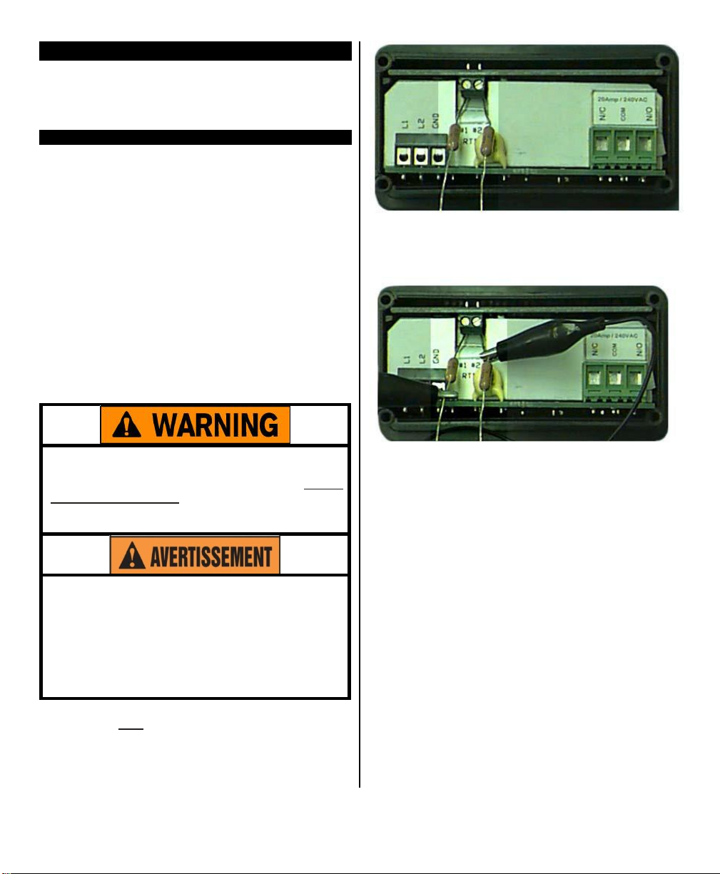
The 2 wire, 1000 ohm RTD sensor must be connected
across terminals #1 AND #2 of the terminal block.
Calibration
RTD devices are precision resistors whose resistance
value varies with temperature. The DE20 control
measures the RTD resistance and compares that
measurement with a “standard” set of values stored in
the control memory. To restore, update or verify that
this “standard” set of values is correct, do the follow-
ing:
Equipment
1. Two precision resistors (tolerance +/0.1% or bet-
ter) with a fixed value equal to the nominal value
of the RTD (i.e. 1000 ohms).
2. A suitable jumper cable to facilitate changing in-
put resistance.
Procedure for the 2 Wire RTD:
needed:
Step 5: Install the jumper cable between the loose
end of one of the resistors and the fixed end of the
other resistor to establish an input value of a single
resistor (i.e. 1000 ohms), as shown.
Step 6: Carefully restore power to the control, taking
precautions not to make contact with any exposed
voltage sources.
Step 7: Press the decrease “” key and increase
“” buttons simultaneously and hold for approximately
6 seconds. The display will indicate “AC.0”. While
the “0” is flashing, use the increase key to change
this to “22”. Press the “SET” key. The control display
will read “CAL1”.
Step 8: Press and hold the “SET” key for 1 second.
The display will read “HoLd”. Wait for the display to
change to “CAL2”.
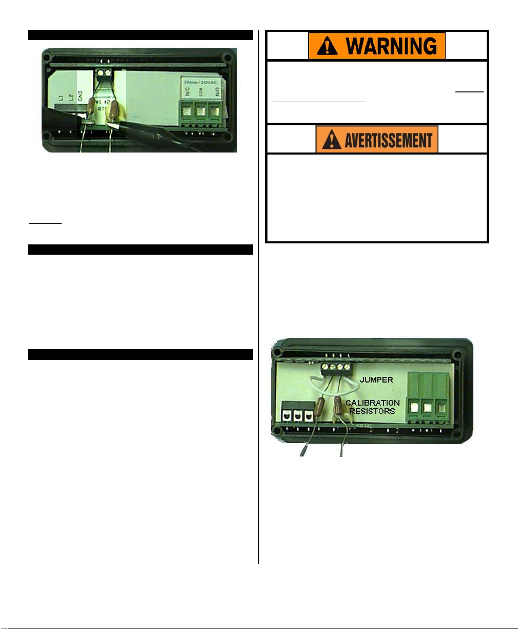
Step 9: Proceed with caution to avoid SHOCK haz-
ard. Remove and relocate one end of the jumper cable
to the loose end of the second precision resistor for
the second resistance value (i.e. 2000 ohms), as
shown.
Step 1: Turn OFF all power.
Step 2: Remove rear cover.
Step 3: Remove RTD sensor.
Step 4: Install the precision resistors in place of the
RTD sensor, as shown.
M-33-01-05 3/19/18
6 DE20/T-DE20 Manual
Page 8
2 Wire RTD Sensor Calibration (Continued)
Calibration procedures require the removal of
the rear cover of the
control.
It also requires that
power is ON, exposing the technician to potentially lethal
voltages.
Exercise
EXTREME
CARE
and
wear tested electrician’s gloves whenever
power is on.
Les procédures de calibration nécessitent
l'enlèvement du panneau arrière du contrôle.
Ça exige aussi que le courant électrique est
allumé ce qui expose le technicien à des tensions potentiellement létales. Utilisez toujours
un soin extrême et portez des gants certifiés
d'électricien quand le courrant est allumé.
Step 10: Press and hold the “SET” key for 1 second.
The display will read “HoLd”. WAIT for the display to
reset. After resetting, the display should indicate the
approximate temperature value for the connected precision resistors (i.e. 511ºF or 266ºC).
Step 11: Turn OFF power and remove the precision
resistors. Reinstall the RTD sensor and the rear cover
of the controller. Return the calibrated control to service
.
Resistance Signal
Optional Item Number 5415 board needed.
The configuration and calibration procedures used
for measuring pure resistance are the same as are
used to configure and calibrate a two wire RTD sensor. However, in the setting configuration mode, the
“U1” sensor type parameter must be set to “12”. See
the “U1” instructions on page 11. The unit will then
measure pure resistance from 0-1000 ohms.
Calibration
Step 1: Turn OFF all power.
Step 2: Remove rear cover.
Step 3: Remove RTD sensor
Step 4: Install the short piece of jumper wire from
terminal #1 to #3.
Step 5: Install the precision resistors in place of the
RTD sensor, as shown in terminals #2 and #3.
procedure for the 3 Wire RTD:
3 Wire RTD Sensor
Note: For a 1000 ohm sensor, the DIP switches
should be OFF, OFF, OFF. For 100 ohm, the DIP
switches should be ON, OFF, OFF (see page 13).
RTD devices are precise resistors whose resistance
value varies with temperature. The DE20 control measures the RTD resistance and compares that measurement with a “standard” set of values stored in the
control memory. To restore, update or verify that this
“standard” set of values is correct, do the following:
Equipment
needed:
1. Two precision resistors (tolerance +/- 0.1% or better) with a fixed value equal to the nominal value of
the RTD (i.e. 1000 ohms or 100 ohms).
Step 6: Install the jumper cable between the loose
end of one of the resistors and the fixed end of the
other resistor to establish an input value of a single
resistor (i.e. 1000 ohms or 100 ohms), as shown.
2. A suitable jumper cable to facilitate changing in-
put resistance.
3. A short piece of jumper wire (simulates third wire).
M-33-01-05 3/19/18 7 DE20/T-DE20 Manual
Page 9
3 Wire RTD Sensor Calibration (Continued)
Calibration procedures require the removal of
the rear cover of the
control.
It also requires that
power is ON, exposing the technician to potentially lethal
voltages.
Exercise
EXTREME
CARE
and
wear tested electrician’s gloves whenever
power is on.
Les procédures de calibration nécessitent
l'enlèvement du panneau arrière du contrôle.
Ça exige aussi que le courant électrique est
allumé ce qui expose le technicien à des tensions potentiellement létales. Utilisez toujours
un soin extrême et portez des gants certifiés
d'électricien quand le courrant est allumé.
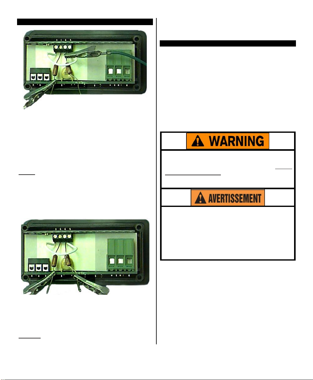
Step 7: Carefully restore power to the controller, en-
suring that you do not come in contact with any exposed voltage.
Step 8: Press the decrease “” key and increase
“”buttons simultaneously and hold for approximately
6 seconds. The display will indicate “AC.0”. While
the “0” is flashing, use the increase key to change this
to “22”. Press the
“CAL1”.
Step 9: Press and hold the “SET” key for one sec-
ond. The display will read “HoLd”. Wait for the display
to change to “CAL2”.
Step 10: Proceed with CAUTION to avoid SHOCK
hazard. Remove and relocate one end of the jumper
cable to the loose end of the second precision resistor
for the second resistance value (i.e. 2000 ohms or
200 ohms), as shown.
“SET”
key. The display will read
use. Reinstall the RTD sensor and rear cover of controller. Return the calibrated control to service.
Th
ermoc
oupl
e
The DE20 can be equipped with an optional thermocouple sensor board (Item Number 5417*). Installation requires configuration for the specific thermocouple used. The two wire thermocouple is polarized,
therefore it is necessary to connect the negative lead
wire of the thermocouple to the #1 terminal, and the
positive lead to the #2 terminal to maintain proper polarity.
Equipment
A precise, NIST traceable, thermocouple calibrator
with suitable extension leads to match the thermocouple type used.
needed:
Step 11: Press and hold the “SET” key for one sec-
ond. The display will read “HoLd”. Wait for the display
to reset. After it resets, the display should indicate the
approximate temperature value for the connected precision resistors (i.e. 511ºF or 266ºC).
Step 12: Turn OFF power to the controller and
remove the precision resistors. Retain for future
M-33-01-05 3/19/18
*Input board 5417 is no longer available
8 DE20/T-DE20 Manual
Page 10
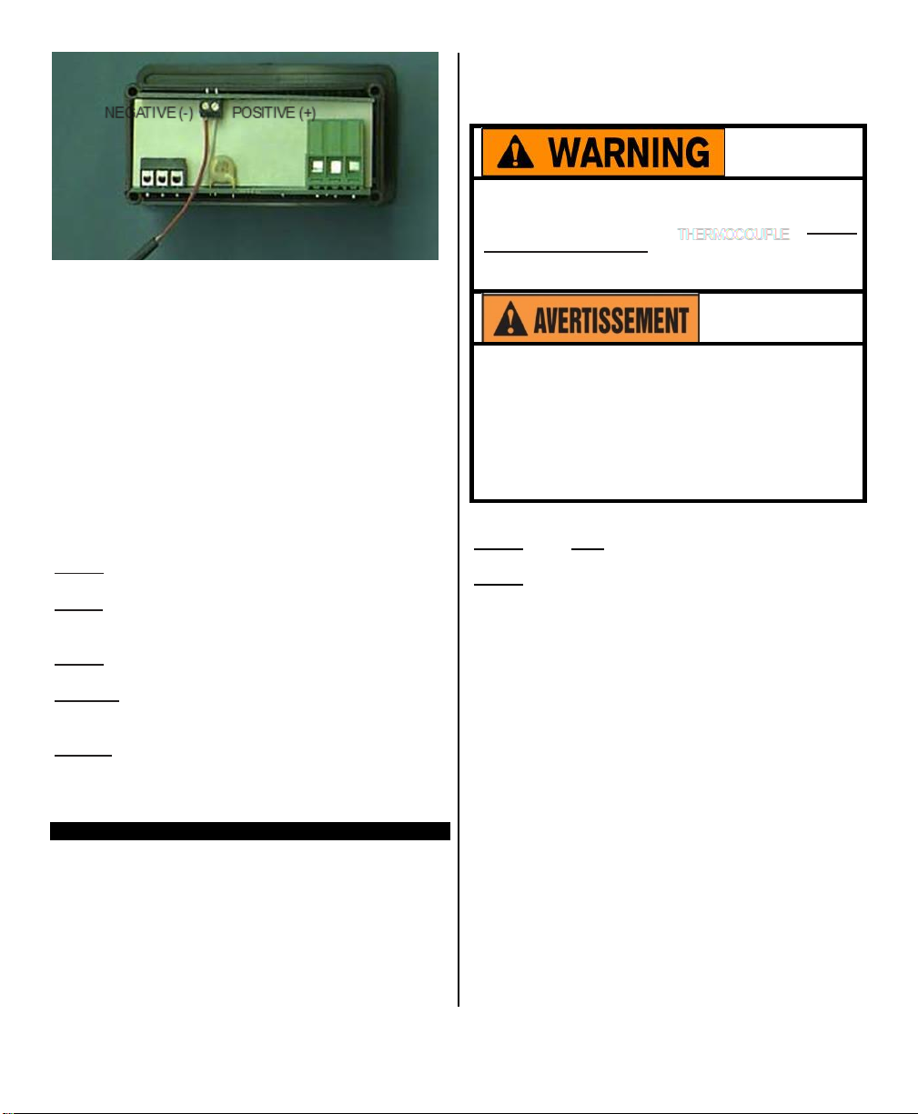
(Item Number 5415). Terminal #1 is common (nega-
Calibration procedures require the removal of
the rear cover of the
control.
It also requires that
power is ON, exposing the technician to potentially lethal
voltages.
Exercise
EXTREME
CARE
and
wear tested electrician’s gloves whenever
power is on.
Les procédures de calibration nécessitent
l'enlèvement du panneau arrière du contrôle.
Ça exige aussi que le courant électrique est
allumé ce qui expose le technicien à des tensions potentiellement létales. Utilisez toujours
un soin extrême et portez des gants certifiés
d'électricien quand le courrant est allumé.
tive), and terminal #2 is the signal connection (positive). Note: Polarity must be observed.
Calibration
Step 1: Turn OFF all power.
Step 2: Remove rear cover.
Step 3: Remove T/C sensor.
Step 4: Install the thermocouple calibrator to terminal
#1 and #2.
Step 5: CAREFULLY restore power to the controller,
making sure that you do not come in contact with any
exposed voltage.
Step 6: Press the decrease “” key and increase
“” buttons simultaneously and hold for approximately
6 seconds. The display will indicate “AC.0”. While
the “0” is flashing, use the increase key to change
this to “22”. Press the “SET” key. The control display
will read “CAL1”.
Step 7: Adjust the thermocouple calibrator to 0.0ºC
(32.0ºF).
Step 8: Press and hold the “SET” key for one sec-
ond. The display will read “HoLd”. Wait for the display
to change to “CAL2”.
Step 9: Adjust the thermocouple calibrator to
250.0ºC (482.0ºF).
Step 10: Press and hold the “SET” key for one sec-
ond. The display will read “HoLd”. Wait for the display
to reset and display 250.0ºC (482.0ºF).
Step 11: Turn OFF power to the control and remove
the thermocouple calibrator. Reinstall the
thermocouple sensor and the rear cover of the
control. Return the control to service.
The DE20 control measures DC voltage and compares that measurement with a “standard” set of values in the control memory. To restore, update or
merely verify that this “standard” set of values is correct, do the following:
Make sure that the DIP switch settings are OFF, ON,
OFF (see page 13). The voltage signal must be
con-nected across terminals #1 and #2 of the Adder
Board
M-33-01-05 3/19/18
procedure for a thermocouple:
Voltage Signal Calibration
Calibration procedure for voltage signal:
Step 1: Turn OFF all power.
Step 2: Remove rear cover.
Step 3: Remove sensor.
Step 4: Install the voltage calibrator to terminal #1 and
#2.
Step 5: CAREFULLY restore power to the controller,
ensuring that you do not come in contact with any exposed voltage.
Step 6: Press the decrease “” key and increase “”
buttons simultaneously and hold for approximately 6
seconds. The display will indicate “AC.0”. While the
“0” is flashing, use the increase key to change this to
“22”. Press the “SET” key. The control display will
read “CAL1”.
Step 7: Adjust the power supply to 1.0 volts.
Step 8: Press and hold the “SET” key for one second.
The display will read “HoLd”. Wait for the display to
change to “CAL2”.
Step 9: Adjust the power supply to 10.0 volts.
Step 10: Press and hold the “SET” key for one sec-
ond. The display will read “HoLd”. Wait for the display
to reset and display 10.0.
Step 11: Turn OFF power to the control and remove
the power supply. Reinstall the voltage input and the
rear cover of the control. Return the calibrated control
to service.
9 DE20/T-DE20 Manual
Page 11
Current Input Calibration
Calibration procedures require the removal of
the rear cover of the
control.
It also requires that
power is ON, exposing the technician to potentially lethal
voltages.
Exercise
EXTREME
CARE
and
wear tested electrician’s gloves whenever
power is on.
Les procédures de calibration nécessitent
l'enlèvement du panneau arrière du contrôle.
Ça exige aussi que le courant électrique est
allumé ce qui expose le technicien à des tensions potentiellement létales. Utilisez toujours
un soin extrême et portez des gants certifiés
d'électricien quand le courrant est allumé.
The DE20 control measures the DC current and compares that measurement with a “standard” set of values in the control memory. To restore, update or
merely verify that this “standard” set of values is correct, do the following:
Check that the DIP switches are set to OFF, OFF, ON
(see page 13).
Equipment
1. A precision, NIST traceable, 0-20 mA DC current
2. A precision, NIST traceable, digital ammeter or
DMM and:
needed:
calibrator, OR
a. a regulated linear DC power supply with
an adjustable 0-10 volt or better output,
and
b. a 400 ohm, 0.1% or better tolerance,
precision resistor.
“” buttons simultaneously and hold for approximately
6 seconds. The display will indicate “AC.0”. While the
“0” is flashing, use the increase key to change this
to “22”. Press the “SET” key. The control display will
read “CAL1”.
Step 7: Adjust the calibrator or power supply to 5.0
mA.
Step 8: Press and hold the “SET” key for one sec-
ond. The display will read “HoLd”. Wait for the display
to change to “CAL2”.
Step 9: Adjust the power supply to 20.0 mA.
Step 10. Press and hold the “SET” key for one sec-
ond. The display will read “HoLd”. Wait for the display
to reset and display 20.0.
Step 11: Turn OFF power to the control and remove
the power supply. Reinstall the voltage input and the
rear cover of the control. Return the calibrated control
to service.
Frequency Signal (Pulse Train)
The T-DE20 control measures frequency and compares that measurement with a “standard” set of values derived from the microprocessor oscillator. Since
this is a dedicated frequency, no field calibration is
possible. Check that the DIP switches are set to OFF,
OFF, OFF (see page 13).
Calibration procedure for a current input:
Step 1: Turn OFF all power.
Step 2: Remove rear cover.
Step 3: Remove input leads.
Step 4: Install the 0-20 mA DC calibrator or the power
supply, resistor and ammeter in series with terminal
#1 and #2.
Step 5: CAREFULLY restore power to the controller,
ensuring that you do not come in contact with any
exposed voltage.
Step 6: Press the decrease “” key and increase
M-33-01-05 3/19/18
10 DE20/T-DE20 Manual
Page 12

Configuration
To enter the configuration mode, press the increase
“” and decrease “” keys simultaneously for approximately 6 seconds (display will first show internal junction value followed by “AC.0”). While the “0” is
flashing, adjust this value to “11” using the increase
“” key. Then press the “SET” key.
The first setting to be displayed is the “U1” setting. See
setting summary below. By using the increase “”,
decrease “” buttons, it is possible to scroll through
the list of settings to those needing modification.
To adjust a setting while in the “Configuration Mode”,
use the increase “”, decrease “” buttons to bring
the particular setting into the view on the display.
Press the “SET” button to change the value of the
setting. Once the “SET” button has been released,
the display will flash. Use the increase “”, decrease
“” buttons to scroll through the options for the selected setting. After the option has been determined,
press the “SET” button once more to lock the new
value into memory.
After completing all changes to the configuration of
the control, the new configuration must be saved. To
save the new value, press the increase “” and decrease “” buttons simultaneously. This will cause
the control to store the new values internally and then
reset the unit.
Note:
Switching
the new configuration will cause all changes to be
lost.
off power to the unit before saving
Main Menu Summary
Label Settings Description
U1 Sensor Type Used to select the type of sensor
U2 Signal Offset Offset value from -9 to +9 applied to reading
U3 N/A
U4
U5 Set Point Dead Band (SP1) Value from 1 to 99 applied to SP1
U6 N/A
U7 N/A
U8 Display Stabilizer Reduces display
L Set Point Limit High set point limit for heat, cool, standby and alarm
F1 N/A
F2
F3 Alarm Enable Toggle flag to enable the “alarm set point” feature
F4
F5 Temperature Unit Toggle flag to select ºF or ºC
F6 N/A
Signal
Filter Adjustable running average filter on input signals
instability
Heat/Cool
Unit
Switch Toggle flag selects relay for direct vs. reverse acting
Display Enable Toggle flag enabling temperature units to be displayed
when used in
conjunction
with U4
M-33-01-05 3/19/18 11 DE20/T-DE20 Manual
Page 13

U1, Sensor
Value
Board
Sensor Type
Sensor Description
1
5413
2-wire RTD
Platinum
RTD, TCR 0.00385 ohm/ohm/ºC
2
5413
2-wire RTD
Platinum
RTD, TCR 0.00392 ohm/ohm/ºC
3
5415
3-wireV RTD
Platinum
RTD, TCR 0.00385 ohm/ohm/ºC
4
5415
3-wire RTD
Platinum
RTD, TCR 0.00392 ohm/ohm/ºC
5
5417*
Thermocouple
J-Type
Iron-Constantan
NIST
Monograph
175 REV ITS-90
6
5417*
Thermocouple
K-Type Chromel-Alumel NIST
Monograph
175 REV ITS-90
7
5417*
Thermocouple
T-Type Copper-Constantan NIST
Monograph
175 REV ITS-90
8
5417*
Thermocouple
R-Type
Platinum,
13%
Rhodium-Platinum
NIST Monograph 175
REV ITS-90
9
5415
Voltage
Potential signal (1.0 to 10.0 V)
10
5415
Current
Current signal (4.00 to 20.00 mA)
11
5415
Frequency
Pulse train frequency (0 to 200 Hz, counts per second)
12
5415
Resistance
Pure resistance signal (0 to 1000 ohms)
Typ
e
This setting tells the DE20 control what type of sensor it is using.
Note: The 5415 sensor board will also accept 2 wire RTDs. The default sensor type setting is “1” (1000
ohm 2 wire RTD). When using the 5415 sensor board, an “on-board” DIP switch must also be configured,
see page 13. *Input board 5417 is no longer available.
U2, Signal Offset
This setting, which may be any number from -9 to +9, represents an offset value which is applied to the signal
received from the sensor. The units (ºC, ºF, ohms, etc.) will be dictated by the type of sensor selected in “U1” settings.
Temperature Sensor Number represents degrees Celsius or Fahrenheit as
determined by the “F5” setting
Voltage Sensor Number represents tenths of a volt (0.1 VDC)
Current Sensor Number represents hundredths of milliamps (0.01 mA)
Resistance Signal Devices Number represents ohms.
Frequency Signal Devices This setting will have no effect.
U3, Output Signal Offset
Not available.
U4,
Signal
Filte
r
This setting, which may be any number from 1 to 64, represents the number of samples taken from the
sensor and maintained in memory. These samples are then averaged to provide an active filter of the signal.
Using a small value for this setting will cause the DE20 control to respond more quickly to sudden changes in
the sensor signal level, but this also causes the unit to be more susceptible to EMI/RFI noise. As this value is
increased, the susceptibility to inference is reduced.
The default value for this setting is four (4).
Note: When sensing temperature with a 100 ohm RTD (2 or 3 wire), set this value to twenty (20) to reduce
control error.
When sensing frequency signal, this setting establishes the time period for the controller to wait for a pulse signal. Use two (2) for this value when measuring frequency. This causes the control to measure frequencies as
low as 1 hertz while updating the display once every two seconds.
M-33-01-05 3/19/18 12 DE20/T-DE20 Manual
Page 14

U5, SP1 Dead Band
This setting, which may be any number from 1 to +99 represents a dead band that only applies to the SP1
POINT.
This is the heat Set Point.
SET
The default and minimum for the setting is one (1).
Temperature Sensor: Number represents degrees C or F as determined by F5 setting
Voltage Sensor: Number represents tenths of a Volt (0.1 VDC)
Current Sensor: Number represents hundredths of milliamps (0.01 mA)
Resistance Signal Devices: Number represents ohms.
Frequency Signal Devices: Setting represents hertz (counts/second)
This bandwidth applies to the low side of the SP1 SET POINT. If the U5 setting is set at 5° F and the SP1 SET
POINT is set at 115° F, then the Set Point relay is de- energized when the (displayed) temperature reaches 115° F
and it is reenergized when the temperature falls to 110° F.
U6, SP2 Dead Band
Not Available
U7, Power Save Set Point Dead Band
Not Available
U8, Display Stabilizer
If the display value changes by a digit or two in a steady state condition, this setting can be altered in conjunction with the U4 setting to reduce the display instability. Lower values cause maximum suppression. Larger
values provide greater accuracy.
The default value for the U8, Display Stabilizer setting is ten (10).
L, Set Point Limit
This setting, which may be any number between -99 and +999, is the maximum limit for all
the ALARM
SET POINT.
This will prevent accidental setting of a Set Point, which could be too high or low (de-
SET POINTS
except
pending upon the application).
Temperature Sensor: Number represents degrees C or F as determined by F5 setting
Voltage Sensor: Number represents tenths of a Volt (0.1 VDC)
Current Sensor: Number represents hundredths of milliamps (0.01 mA)
Resistance Signal Devices: Number represents ohms.
Frequency Signal Devices: Setting represents hertz (counts/second)
The default value for this setting is +999.
F1, Emulation Flag
Not available
F2, Heating or Cooling Switch
When the setting is turned OFF (0), then the relay is reverse acting. That is, when a sensor reports a
temperature less than the SET POINT, the relay is energized. At temperatures greater than the SET
POINT, the relay is de-energized. This setting is common for heating applications.
M-33-01-05 3/19/18 13 DE20/T-DE20 Manual
Page 15
F3, Alarm On/Off
Sw1
Sw2
Sw3
Type
OFF
OFF
OFF
1000 ohm RTD
ON
OFF
OFF
100 ohm RTD
OFF
ON
OFF
voltage
OFF
OFF
ON
current
OFF
OFF
OFF
frequency
Switch
This setting may be a zero (0) or a one (1). When set to zero, the alarm set point is turned off. When set to one,
alarm set point is turned on.
The default value for this setting is zero (0).
F4, Unit Display Enable Flag
This setting may be set to a zero (0) or a one (1). When set to one (1), the DE20 will display either a “C” or an
“F”, separated by a decimal point. This indicates that either Celsius or Fahrenheit is being displayed. If the tem-
perature being measured is greater than +999 degrees, the units are not shown because the display is limited
to four positions.
F5, Temperature Units Conversion
This setting may be set to a zero (0) or a one (1). When set to a zero (0), the temperature is displayed in
degrees Fahrenheit. When set to a one (1), the temperature is displayed in degrees Celsius.
Conversion from F to C does NOT change set point or alarm upper limit values. These must be changed
manually.
The default setting is zero (0).
F6, Current Output Enable Flag
Not available.
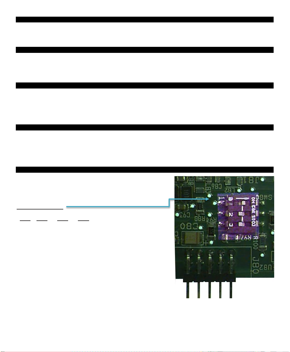
Sensor DIP Switch Settings
When using the sensor 5415 board, an “on-board”
DIP switch must also be configured. The DIP
switch settings are as follows:
Sensor DIP Switch:
Selections
(Illustration shows
DIP switch setting for 100
ohm
RTD.)
M-33-01-05 3/19/18 14 DE20/T-DE20 Manual
Page 16
Electrical Noise and Interference
Process Technology electronic controls are engineered, tested and manufactured to conform to Europe’s CE
levels of electrical noise and interference found in typical industrial installations. It is always possible for
electrical noise and interference to exceed the level of designed-in protection. This can happen, for example, if
arc or spot-welding equipment is close to the control or if they share a common power line. It can occur if
flame ignition systems or electrostatic precipitators are in the vicinity of the control. A more common source of
interference occurs when the control is switching inductive loads such as contactor coils, solenoids or motors.
The collapse of the magnetic field when loads such as these are switched off can create an electrical “spike”
that can cause a malfunction of the microprocessor used in the control. Even if the control doing the switching
is unaffected, a nearby control may be affected. To eliminate or minimize this problem, transient suppressors
or “snubbers” can be employed across the inductive load.
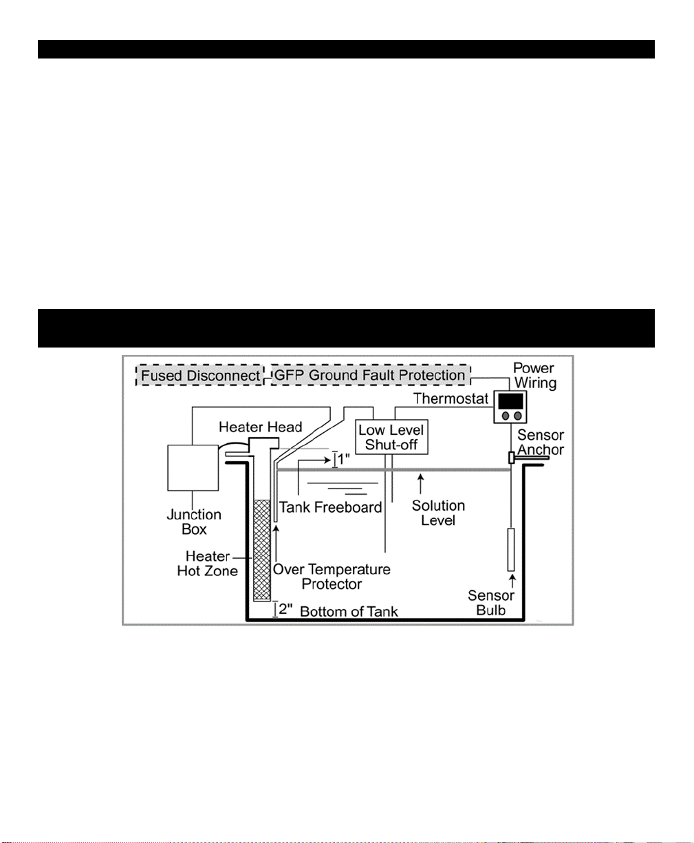
Illustration of a Typical Heater In Illustration of a Typical Heater Installation in a
Process Tank
CONSULT INSTALLATION
M-33-01-05 3/19/18 15 DE20/T-DE20 Manual
AND
MAINTENANCE INFORMATION
FOR
SPECIFIC
INSTRUCTIONS
 Loading...