

Page 1

INSTALLATION,
OPERATION
AND
MAINTENANCE
MANUAL
UNITIZED HEATER
PROCESS HEATING COMPANY, INC.
POST OFFICE BOX 84585
SEATTLE, WASHINGTON 98124-5885
PHONE: (206) 682-3414 FAX: (206) 682-1582
KIT
Page 2

WARNINGS
1) READ AND UNDERSTAND ALL TAGS AND INSTALLATION AND
OPERATING INSTRUCTIONS BEORE COMMENCING.
2) CHECK THAT THE ELECTRICAL SERVICE WILL HANDLE THE LOAD.
UNIT MUST BE ADEQUATELY GROUNDED.
3) ALL WIRING SHOULD CONFORM TO REQUIREMENTS OF NATIONAL
AND LOCAL ELECTRICAL CODES AND STANDARDS.
4) ONLY LICENSED ELECTRICIAN SHOULD CONNECT POWER TO PANEL
AND SYSTEM.
5) NEVER EXPOSE HEATER TUBES TO AIR WITH POWER ON.
6) CARE SHOULD BE USED WHEN WORKING AROUND TUBES WHEN
CLEANING OR INSTALLING. WALLS ARE LESS THEN ¼” THICK.
7) IF THERE ARE ANY QUESTIONS CONCERNING THE RATINGS OR
INSTRUCTIONS PLEASE CONTACT YOUR LOCAL DISTRIBUTOR OR THE
FACTORY. PHONE (206) 682-3414 FAX (206) 682-1582
2
Page 3

ADDITIONAL IMPORTANT INFORMATION
1) THESE INSTRUCTIONS CANNOT POSSIBLY COVER EVERY SITUATION
CONCERNING THE OPERATION, INSPECTION, ADJUSTMENT AND TEST
OF THE EQUIPMENT FURNISHED. PROCESS HEATING COMPANY
(PHCo), IN THE FURNISHING OF THIS EQUIPMENT AND THESE
INSTRUCTIONS, MUST PRESUME THAT THE OPERATING AND
MAINTENANCE PERSONEL USING THIS EQUIPMENT HAVE SUFFICIENT
TECHNICAL KNOWLEDGE AND EXPERIENCE TO APPLY SOUND
SAFETY AND OPERATIONAL PRACTICES WHICH MAY NOT BE
MENTIONED.
2) IN APPLICATIONS WHERE PHCo FURNISHED EQUIPMENT THAT IS TO
BE INTEGRATED WITH A PROCESS OR OTHER EQUIPMENT, THESE
INSTRUCTIONS SHOULD BE THOROUGHLY REVIEWED TO DETERMINE
THE PROPER INTEGRATION OF THE EQUIPMENT INTO THE OVERALL
PLANT OR SYSTEM OPERATIONAL PROCEDURES.
3) PHCo DOES NOT SUPPLY, RECOMMEND OR APPROVE THE VARIOUS
SYSTEMS IN WHICH ITS PRODUCTS ARE OR MAY BE USED. UNLESS
DESIGNED, MANUFACTURED AND USED PROPERLY, VARIOUS
SYSTEMS MAY BE INHERENTLY UNSAFE OR DANGEROUS. THE USER
SHOULD CHECK AND COMPLY WITH ALL FEDERAL, STATE AND LOCAL
REGULATIONS AND OTHER REGULATIONS AND RECOMMENDATIONS
SUCH AS: NFPA, UL, API, OSHA, ETC.
3
Page 4

PREPERATION
1) REMOVE JACKETING AND INSULATION FROM SECTION OF TANK
HEATER IS TO BE INSTALLED THROUGH.
2) MARK LOCATION OF OPENING ON TANK. HEATER SHOULD BE
KEPT AS LOW AS POSSIBLE IN TANK.
CAUTION
BEFORE BURNING OR WELDING ON TANK, CLEAN THOROUGHLY
AND KEEP WELL VENTILATED.
INSTALLATION
1) BURN OPENING IN TANK SLIGHTLY LARGER THAN HEATER TERMINAL
BOX (SNUG FIT). REMOVE SLAG AND GRIND OPENING SMOOTH.
2) REMOVE BLOCKING FROM SUPPORT PLATE(S) AND SLIDE HEATER
THROUGH OPENING IN TANK. STOP AT MARKED “WELD LINE” ON
HEATER TERMINAL BOX.
3) HEATER TUBE SUPPORT PLATE(S) SHOULD BE ATTACHED TO TANK
BOTTOM. LEVEL HEATER TUBES AND WELD SUPPORT(S) TO TANK.
DO NOT
4) WELD HEATER TERMINAL BOX TO TANK. TERMINAL BOX IS ¼”
THICK STEEL. WELD MUST BE LIQUID TIGHT.
5) TANK DISCHARGE SHOULD BE KEPT 2” TO 3” ABOVE HEATER TUBES.
NEVER EXPOSE HEATER TUBES TO AIR WITH POWER ON.
6) HAVE LICENSED ELECTRICIAN CONNECT PROPER VOLTAGE AND
PHASE TO THE LINE SIDE OF THE MAIN DISCONNECT SWITCH USING
SUITABLE WIRE GAUGE FOR HEATER LOAD. UNIT MUST BE
PROPERLY GROUNDED.
7) CHECK ALL CONNECTIONS TO INSURE THEY ARE ALL TIGHT SINCE
VIBRATION IN TRAVEL CAN LOOSEN WIRE CONNECTIONS.
WELD HEATER TUBES TO SUPPORT PLATE(S).
4
Page 5

OPERATION
1) TURN ON THE MAIN DISCONNECT SWITCH.
2) PUSH THE RED HIGH LIMIT RESET PUSHBUTTON TO PULL IN THE
CONTACTOR AND PROVIDE LOAD POWER.
3) THE INDICATING TEMPERATURE CONTROL (IN ENCLOSURE DOOR)
SHOULD BE SET TO DESIRED PROCESS TEMPERATURE BY PRESSING
UP/DOWN ARROWS AND THEN PRESSING ENTER (HALF CIRCLE) KEY
(FACTORY SET TO 125°F).
4) THE HIGH LIMIT CONTROL (PROCESS TEMPERATURE SENSING) IN
THE PANEL, MOUNTED ON THE BACK PANEL UNDER THE MAIN
CONTROLLER TO THE LEFT SIDE, SENSES PROCESS TEMPERATURE
AND WILL DISCONNECT POWER TO THE HEATERS IF OVER
TEMPERATURE OCCURS. SETPOINT SHOULD BE APROXIMATELY 20°
TO 25°F ABOVE PROCESS TEMPERATURE. WHEN THE TEMPERATURE
RETURNS TO BELOW THE HIGH LIMIT SETPOINT THE POWER WILL
RETURNED TO THE HEATING CIRCUIT ALLOWING THE HEATERS TO
COME ON BUT THE RED HIGH LIMIT RESET PUSHBUTTON WILL BE
ILLUMINATED UNTIL MANUALLY RESET (INDICATING THAT THERE WAS
A HIGH LIMIT OCCURANCE). THE CAUSE OF THE MALFUNCTION
SHOULD BE INVESTIGATED AT ONCE. POSSIBLE REASONS ARE:
• Thermocouple failure on the main temperature controller (indicated by “no”
in the upper display of the controller).
• “Over Ranging” of the main temperature controller (indicated by “over” in
upper display).
• Temperature controller setting higher then Hi-Limit controller setting.
• Main temperature controller out of calibration.
• Hi-Limit controller out of calibration.
• Heater magnetic contactor locked in closed position because of “welded”
contacts or mechanical binding.
5
Page 6

MAINTANENCE
1) PERIODICALLY CHECK ALL WIRING CONNECTIONS TO INSURE THEY
ARE TIGHT AND FREE OF OXIDATION.
2) PERIODICALLY CHECK CONTACTS ON THE CONTACTORS FOR WEAR
AND REPLACE CONTACTOR IF WORN.
3) TANK SHOULD BE CLEANED AT REGULAR INTERVALS.
4) BE SURE TO SEE THAT TANK HAS ADEQUATE INSULATION.
INSULATION TENDS TO BREAK DOWN IN TIME THUS COSTING
DOLLARS IN LOST EFFICIENCY.
6
Page 7

on
PHCo
Products
Manufactured by
Process Heating Company
THE ABOVE WARRANTY IS SUBJECT TO THE TERMS &
and delivered to the initial user are subject to the fol-
lowing limited warranty: PHCo warrants its Patented
Heating Elements to be free from defects in workmanship
and materials for a period of five (5) years (one (1) year
for drop-in style) after the date of delivery to the initial
user when operated under normal use and service and in
accordance with printed instructions provided by PHCo.
All other parts and components provided by PHCo as
part of the unit are warranted to be free from defects in
material and workmanship for a period of one (1) year
from date of delivery to the initial user.
CONDITIONS ON THE REVERSE SIDE OF THIS DOCUMENT
Page 8

, INCLUD-
OTHER
nship and materials
, OR FOR ANY
less the same is in writ-
o its transaction with you (the
r after tender of delivery (five (5)
f such fact within thirty (30)
y are exclusive of all other
er the purchase price paid for that
aim relating to any item sold.
lity on account of any claim as-
r with a non-defective item), then
basis, if PHCo’s liability on account
o.
that is greater than their normal.
terms of this contract.
waived or varied by course of
tute a waiver of the same or any
rules. Any action to enforce
or state court located in King
jurisdiction over them person-
be dismissed at the instance of
ontract, tort or otherwise) may be com-
-in style elements), and if Buyer notifies PHCo in writing o
OTHERS FOR ANY SPECIAL, INCIDENTAL OR CONSEQUENTIAL DAMAGES
Unless otherwise agreed in writing by Process Heating Company (“PHCo”), all of the following terms & conditions shall apply t
“buyer”):
1. LIMITED WARRANTY; DISCLAIMERS. PHCo warrants that the goods sold under this contract shall be free from defects in workma
at the time delivery is tendered. If there is discovered any failure of goods to conform to this warranty within one (1) yea
years in the case of immersion type heating elements other than drop
days following such discovery, PHCo at its own expense either will repair the defective item, or replace it, or refund to Buy
item (with choice between repair, replacement or refund to be made solely by PHCo). The foregoing limited warranty and remed
warranties, express or implied, and constitute PHCo’s exclusive liability, and Buyer’s exclusive remedy, on account of any cl
PHCo DISCLAIMS ANY WARRANTY OF MERCHANTABILITY OR FITNESS FOR ANY PARTICULAR PURPOSE. If PHCo should elect to repair or replace a
defective item and if for any reason the repair or replacement should fail in its essential purpose (which is to provide Buye
PHCo’s liability nevertheless shall be limited to the purchase price charged by PHCo for the goods. PHCo shall have no liabi
serted under principles of negligence or other tort, breach of any statutory duty, indemnity or contribution, or on any other
of such claim would exceed or in any respect differ from its liability under forgoing limited warranty and exclusive remedy.
2. LIABILITY OF PHCo UNDER THE FOREGOING LIMITED WARRANTY SHALL EXIST ONLY IF: a. The goods are installed, operated and tested in accordance with the PHCo approved installation and operation instruction. b. The goods are used and maintained in conformity with installation and operation instructions approved or published by PHC
c. Written authorization must be given by PHCo before any warranty work is done. The above limited warranty shall be void and no longer in effect if the goods are subject to abuse, strain, impact or loading
3. LIMITATION OF LIABILITY. UNDER NO CIRCUMSTANCES SHALL PHCO OR ANYONE ELSE INVOLVED IN THE MANUFACTURE OR
SALES OF THE GOODS BE LAIBLE TO BUYER OR
ING BUT NOT LIMITED TO LOST PROFITS, EVEN IF PHCO HAS BEEN ADVISED OF THE POSSIBILTY OF SUCH DAMAGES
DAMAGES OR SUMS PAID BY BUYER OR OTHER THIRD PARTIES. THE FOREGOING LIMITATION OF LIABILITY SHALL APPLY
WHETHER ANY CLAIM FOR ANY SUCH DAMAGES IS BASED UPON PRINCIPLES OF CONTRACT, WARRANTY, NEGLIGENCE OR
TORT, BREACH OF STATUTORY DUTY, PRINCIPLES OF INDEMNITY OR CONTRIBUTION, THE FAILURE OF ANY LIMITED OR EXCLUSIVE
REMEDY TO ACHIEVE ITS ESSENTIAL PURPOSE, OR ANY OTHER BASIS.
4. AUTHORITY OF PHCo’s AGENTS. No agent, employee or representative of PHCo has any authority to bind PHCo to any other affirmation, representa-
tion, promise or warranty concerning the goods sold under this contract, unless it is in writing and included as part of the
5. MODIFICATION OF WAIVER. No subsequent waiver or modification of this Limited Warranty and Liability shall be effective un
ing and signed by the party against whom such waiver or modification is asserted. No waiver in any one instance shall consti
other term or condition on any subsequent occasion. None of the express terms of this Limited Warranty and Liability may be
dealing or usage of trade.
6. DISPUTES. This agreement shall be governed by the laws of the State of Washington without reference to its choice of law
any of the terms or conditions of this agreement may be commenced or maintained at the option of either party in any federal
County, Washington having jurisdiction over the matter, and both parties consent in advance to the exercise by such courts of
ally. No action by either party arising out of or relating to this contract (including any action based upon principles of c
menced more than one (1) year after the cause of the action has accrued, and any action commenced by a party thereafter shall
the other party.
Page 9
2006-02-15
Bulletin E-90-C
5011643800-DWC0
C Series Temperature Controller
Instruction Sheet
Thank you very much for purchasing a Love Controls Series C Temperature Controller. Please read this instruction sheet before using
your controller to ensure proper operation and please keep this instruction sheet handy for quick reference.
1 Precaution
DANGER! Caution! Electric Shock!
1. Do not touch the AC terminals while the power is supplied to the controller to prevent an electric shock.
2. Make sure power is disconnected while checking the unit inside.
3. The symbol
(equivalent to Class II of IEC 536).
WARNING!
Mount the controller in a location that will not be subject to excessive temperature, shock, or vibration. All models are designed for
mounting in an enclosed panel..
1. Always use recommended solder-less terminals: Fork terminal with isolation (M3 screw, width is 7.0mm, hole diameter 3.2mm).
Screw size: M3 x 6.5 (With 6.8 x 6.8 square washer). Recommended tightening torque: 0.4 N.m (4kgf.cm). Applicable wire:
Solid/twisted wire of 2 mm
2. Do not allow dust or foreign objects to fall inside the controller to prevent it from malfunctioning.
3. Never modify or disassemble the controller.
4. Do not connect anything to the “Not used” terminals.
5. Make sure all wires are connected to the correct polarity of terminals.
6. Do not install and/or use the controller in places subject to: Dust or corrosive gases and liquid, high humidity and high radiation,
vibration and shock, high voltage and high frequency
7. Power must be off when wiring and changing a temperature sensor.
8. Be sure to use compensating wires that match the thermocouple types when extending or connecting the thermocouple wires.
9. Please use wires with resistance when extending or connecting a platinum resistance sensor (RTD).
10. Please keep the wire as short as possible when wiring a platinum resistance sensor (RTD) to the controller and please route
power wires as far as possible from load wires to prevent interference and induced noise.
11. This controller is an open-type unit and must be placed in an enclosure away from high temperature, humidity, dripping water,
corrosive materials, airborne dust and electric shock or vibration.
12. Please make sure power cables and signals from instruments are all installed properly before energizing the controller, otherwise
serious damage may occur.
13. Please do not touch the terminals in the controller or try to repair the controller when power is applied to prevent an electric
shock.
14. Wait at least one minute after power is disconnected to allow capacitors to discharge, and please do not touch any internal circuit
within this period.
15. Do not use acid or alkaline liquids for cleaning. Please use a soft, dry cloth to clean the controller.
16. This instrument is not furnished with a power switch or fuse. Therefore, if a fuse or power switch is required, install the protection
close to the instrument. Recommended fuse rating: Rated voltage 250 V, Rated current 1 A. Fuse type: Time-lag fuse
17. Note: This controller does not provide overcurrent protection. Use of this product requires that suitable overcurrent protection
device(s) must be added to ensure compliance with all relevant electrical standards and codes. (Rated 250 V, 15 Amps max). A
suitable disconnecting device should be provided near the controller in the end-use installation.
indicates this Controller is protected throughout by DOUBLE INSULATION or REINFORCED INSULATION
2
, 12AWG to 24AWG. Please be sure to tighten them properly.
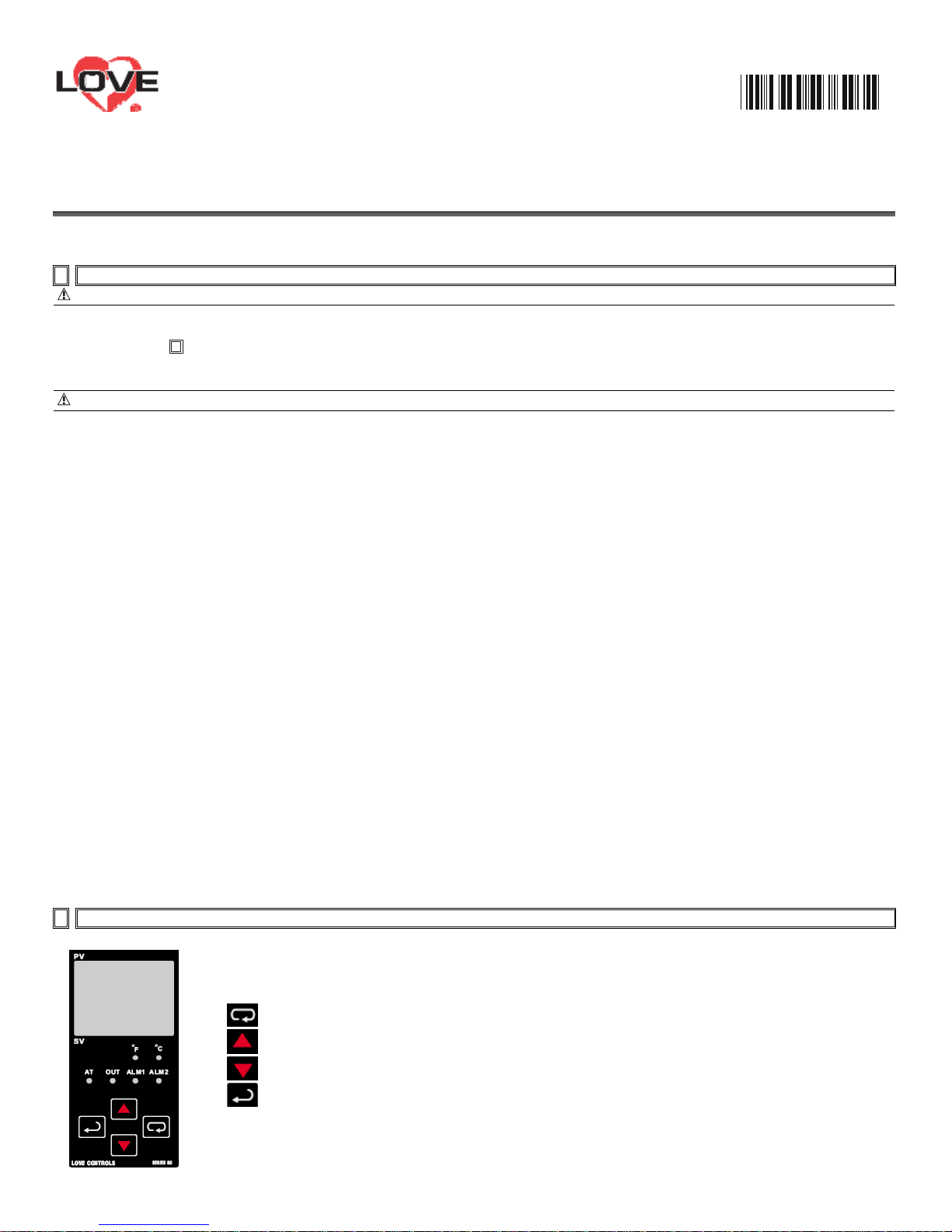
2 Display, LED, and Pushbuttons
PV displays process value
SV displays setpoint value.
INDEX: advances the display to the next menu item.
UP ARROW: Increments a value or changes a menu item.
DOWN ARROW: Increments a value or changes a menu item.
ENTER: stores the value or item change.
Page 10
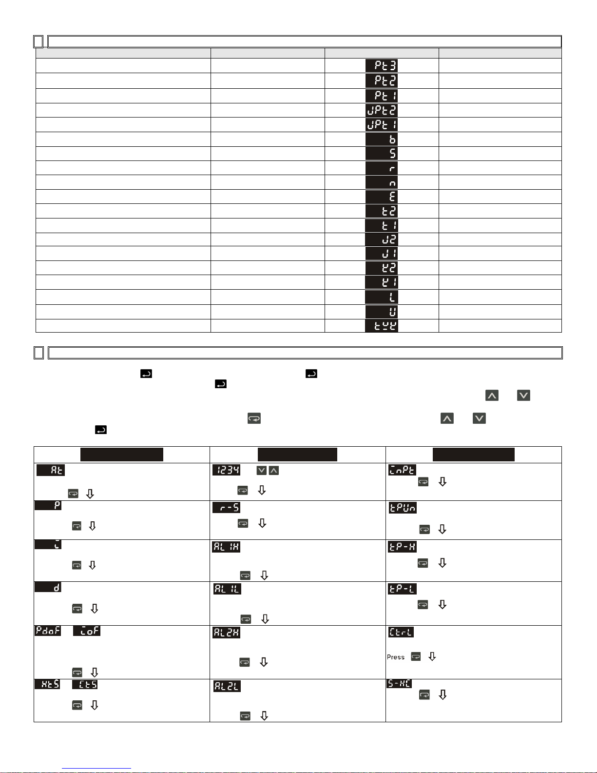
3 Temperature Sensor Type and Temperature Range
Input Temperature Sensor Type Register Value LED Display Temperature Range
Platinum resistance (Pt100) type3 15
Platinum resistance (Pt100) type2 14
Platinum resistance (Pt100) type1 13
Platinum resistance (JPt100) type2 12
Platinum resistance (JPt100) type1 11
Thermocouple (TC) B type 10
Thermocouple (TC) S type 9
Thermocouple (TC) R type 8
Thermocouple (TC) N type 7
Thermocouple (TC) E type 6
Thermocouple (TC) T type2 5
Thermocouple (TC) T type1 4
Thermocouple (TC) J type2 3
Thermocouple (TC) J type1 2
Thermocouple (TC) K type2 1
Thermocouple (TC) K type1 0
Thermocouple (TC) L type 16
Thermocouple (TC) U type 17
Thermocouple (TC) Txk type 18
0.0 to 100.0
-20.0 to 500.0 oC
-200 to 600
0.0 to 100.0
-20.0 to 400.0
100 to 1800
0 to 1700
0 to 1700
-200 to 1300
0 to 600
-20.0 to 400.0
-200 to 400
-20.0 to 400.0
-100 to 850
-20.0 to 500.0
-200 to 1300
-200 to 850 oC
-200 to 500
-200 to 800
o
C
o
C
o
C
o
C
o
C
o
C
o
C
o
C
o
C
o
C
o
C
o
C
o
C
o
C
o
C
o
C
o
C
4 Operation
There are three modes of operation: operation, regulation and initial setting. When power is applied, the controller will default to the
operation mode. Press the
switch to the initial setting mode. Pressing the key while in the regulation mode or initial setting mode, forces the controller to return
to the operation mode. PV/SV : Sets the temperature set point and displays the temperature process value. Use the and keys to
set the temperature set point.
Setting method: While in any function mode, press the key to select the desired function and use the and keys to change
settings. Press
key to save the changes. Menu items are listed below.
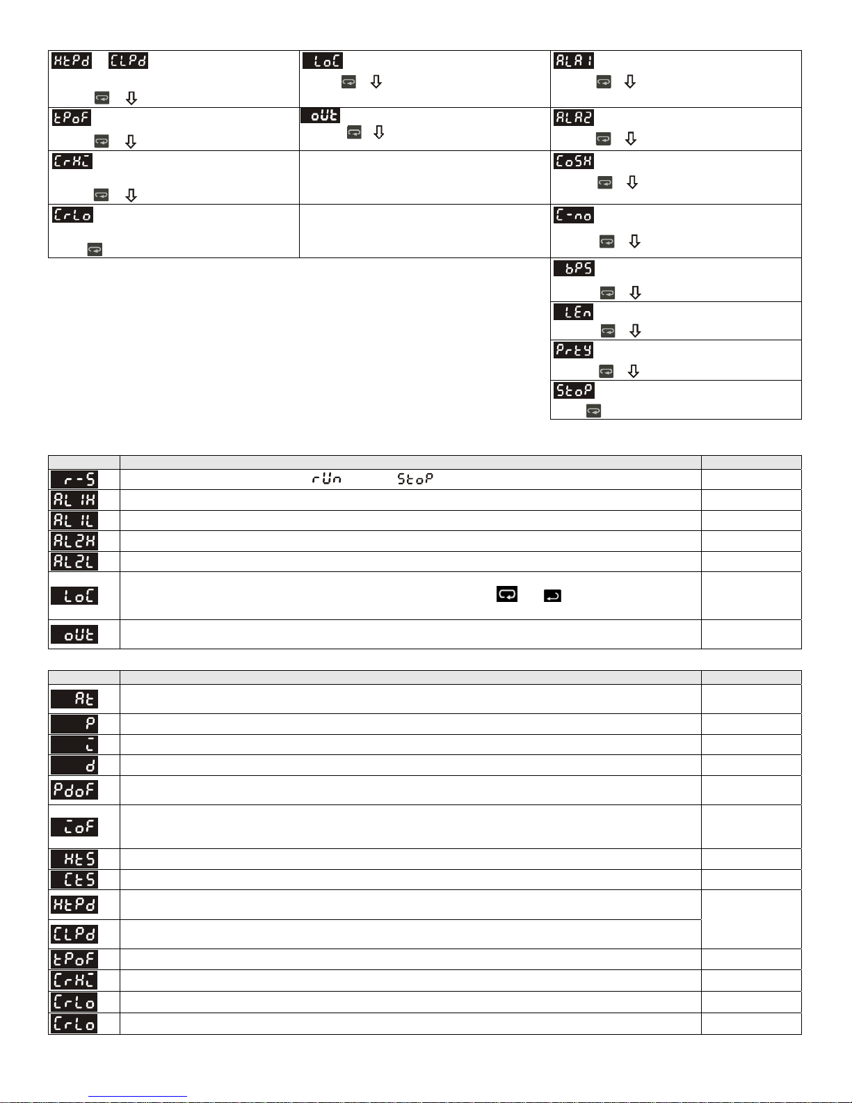
Regulation Mode
Auto-tuning
(Set in PID control and RUN mode)
Press
Set proportional band (Kp)
(in PID control)
Press
Set integral time (Ki)
(in PID control)
Press
Set derivative time (Kt)
(in PID control)
Press
or P/PD control offset (when
PID control is ON and Ki=0 set the value of
PdoF. If Ki≠0, AT (auto-tuning, will
automatically set the value of ioF.
Press
or Heating/Cooling hysteresis.
(in ON/OFF control)
Press
key to switch to regulation mode. If the key is pressed for more than 3 seconds, the controller will
set temperature set point
Press
Press
(This parameter is available only when
ALA1 function enables)
Press
(This paramete r is available only when
ALA1 function enables)
Press
(This parameter is available only when
ALA2 function enables)
Press
(This parameter is available only when
ALA2 function enables)
Press
Operation Mode
Use key to
Control setting RUN or STOP
Upper-limit alarm 1
Lower-limit alarm 1
Upper-limit alarm 2
Lower-limit alarm 2
Press
do not display when analog input
Press
Press
Press
manual.
Press
Initial Setting Mode
Set input type
Set temperature unit
Set upper-limit of
temperature range
Set lowe r-li m it o f
temperature range
Sets Control Method: on/off, PID, or
Select heating or cooling control.
Page 11
or
(Set in PID control mode)
Press
Regulate temperature
deviation value
Press
Regulate upper-limit of analog
output value
(The setting display when analog output)
Press
Regulate lower-limit of analog
(The setting display when analog output)
Press
output value
to return to auto-tuning mode
Heating/Cooling
control cycle setting
Press
Setting lock mode
Press
Display and adjust output value.
Alarm 1 mode setting
Press
Alarm 2 mode setting
Press
Communication write function
enable/disable
Press
Communication address
setting
Press
Communication baud
rate setting
Press
Data length setting
Press
Pari ty bit sett ing
Press
Stop bit setting
Pres s to ret ur n in pu t ty p e se ttin g
Parameters List
1. Operation Mode: The default mode after start-up
LED Explanation Default
RUN/STOP: Control setting. Run (
ALARM 1 HIGH: Upper limit for alarm 1. (Only available when alarm is set in the initial setting mode).
ALARM 1 LOW: Lower limit for alarm 1. (Only available when alarm is set in the initial setting mode).
ALARM 2 HIGH: Upper limit for alarm 2. (Only available when alarm is set in the initial setting mode).
ALARM 2 LOW: Lower limit for alarm 2. (Only available when alarm is set in the initial setting mode).
) or Stop ( ) mode on the SV display.
RUN
o
4.0
o
4.0
o
4.0
o
4.0
C
C
C
C
Lock Function Setting: LoC1, LoC2, or OFF. LoC1 mode will lock all settings, LoC2 locks everything
except the setpoint value, and OFF will not lock any settings. Press
release the lock status.
and keys simultaneously, to
OUT: The Output value adjustment and display in manual tuning control. (Not available in ON/OFF or
Auto-tuning control).
OFF
0
2. Regulation Mode: Control parameters Settings
LED Explanation Default
AT (Auto-Tuning): ON or OFF, when set ON, the execution of the auto-tuning function in PID control
mode is automatically started. (Only available when PID control is selected in initial settings)
P (Proportional Band in PID control): Sets P value. 47.6
I (Integral Time in PID control): Sets I value. 260
D (Derivative Time in PID control): Sets D value. 41
PdoF: Offset output when P or PD control function is on. PID in initial settings is selected and the value
of Ki (Integral Time in regulation mode) is equal to zero.
OFF
0
ioF: Default value of integral volume when PID control is ON and the Ki (Integral Time in regulation
mode) is not equal to zero. AT function can automatically set this parameter when PID control is active
and Ki≠0.
HtS (Heating Hysteresis): Available only in ON/OFF control. Sets the value the heating hysteresis. 0
CtS (Cooling Hysteresis): Available only in ON/OFF control. Sets the value the cooling hysteresis. 0
HtPd: PID heating control cycle setting. Only available when a PID control is selected in the initial
settings.
ClPd: PID cooling control cycle setting. Only available when a PID control is selected in the initial
settings.
TPoF: Regulates the temperature deviation value. 0
CrHi: Regulates the 20 mA output deviation value. 0
CrLo: Regulates the 4 mA output deviation value. 0
HtS (Heating Hysteresis): Available only in ON/OFF control. Sets the value the heating hysteresis. 0
0
Output Selection:
Voltage: 4 sec.
Relay : 20 sec.
Page 12
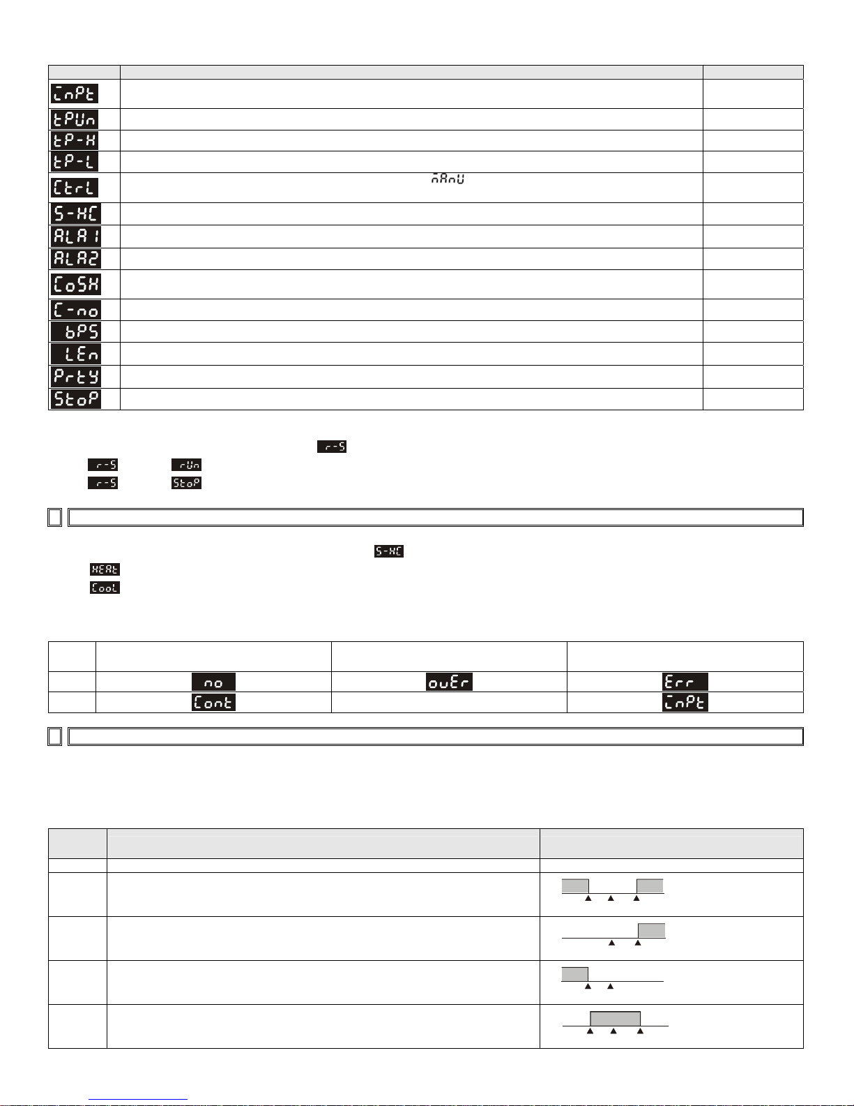
3. Initial Setting Mode: Initial settings of the controller and communication parameters
LED Explanation Default
INPUT: Select input temperature sensor type
(Please refer to the contents of the “Temperature Sensor Type and Temperature Range” for detail)
Engineering Unit(°F or °C): Select engineering unit F or C.
T-High: Upper limit for temperature range. 500.0
T-Low: Lower limit for temperature range. -20.0
CONTROL METHOD (ON/OFF, PID, or manual tuning [
point value.
Control Action (Direct or Reverse Acting): Cooling [Cool] or heating [HEAT]. HEAT
ALARM 1: Alarm 1 setting. (See Alarm Output Section for set values and descriptions). 0
ALARM 2: Alarm 2 setting. (See Alarm Output Section for set values and descriptions).
]): Sets the control method for the set
C WE: Write-in function disabled/enabled. Can be set only when unit is equipped with serial
communication.
C NO: Address setting. Can be set only when unit is equipped with serial communication.
BPS: Baud rate setting. Can be set only when unit is equipped with serial communication.
Length: Data length setting. Can be set only when unit is equipped with serial communication.
Parity: Parity bit setting. Can be set only when unit is equipped with serial communication.
Stop Bit: Stop bit setting. Can be set only when unit is equipped with serial communication.
PT2
o
C
PID
0
OFF
1
9600
7
E
1
Execution :
The programming execution is initiated through in the operation mode.
When
When
is set to , the program will start to execute in order from the step 0 of the start pattern.
is set to , the program will stop and the control output is disabled
5 Heating and Cooling
Temperature control can be achieved either by heating or cooling. Please refer to the following for the operation: Settings for heat or
cool operation are found in the initial settings mode under .
Select
Select
, for heating (reverse) control on Output 1.
, for cooling (forward) control on Output 1
Input Error Indication
Setting
value
PV
SV
Temperature sensor is not connected
Measured temperature value exceeds
the temperature range
Unknown input
6 Alarm Outputs
Depending on the controller model, there can be up to two alarm outputs. Each alarm output can be configured for an alarm type
listed below. Alarm types are set in the initial setting mode. The alarm output is activated whenever the process temperature value
(PV) is getting higher or lower than the set point of alarm limit.
Set
Value
0 Alarm function disabled Output OFF
Deviation upper- and lower-limit:
This alarm output operates when PV value is higher than the setting value
1
SV+(AL-H) or lower than the setting value SV-(AL-L).
Deviation upper-limit:
2
This alarm output operates when PV value is higher than the setting value
SV+(AL-H).
Deviation lower-limit:
3
This alarm output operates when PV value is lower than the setting value
SV-(AL-L).
Reverse deviation upper- and lower-limit:
4
This alarm output operates when PV value is in the range of the setting value
SV+(AL-H) and SV-(AL-L).
Alarm Type Alarm Output Operation
ON
OFF
SV-(AL-L)
ON
OFF
ON
OFF
SV-(AL-L)
ON
OFF
SV-(AL-L)
SV
SV
SV
SV
SV+(AL-H)
SV+(AL-H)
SV+(AL-H)
Page 13
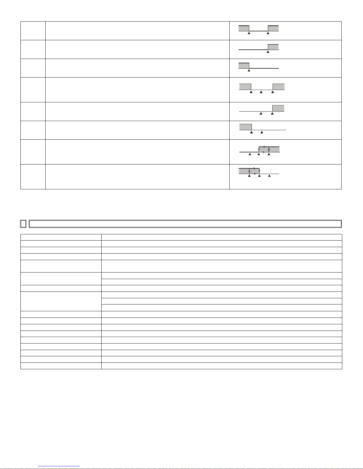
Absolute value upper- and lower-limit:
This alarm output operates when PV value is higher than the setting value
5
AL-H or lower than setting value AL-L.
Absolute value upper-limit:
This alarm output operates when PV value is higher than the setting value
6
AL-H.
Absolute value lower-limit:
This alarm output operates when PV value is lower than the setting value AL-
7
L.
Deviation upper- and lower-limit with standby sequence:
This alarm output operates when PV value reaches set point (SV value) and
8
the value is higher than the setting value SV+(AL-H) or lower than the setting
value SV-(AL-L).
Deviation upper-limit with standby sequence:
This alarm output operates when PV value reaches set point (SV value) and
9
the reached value is higher than the setting value SV+(AL-H).
Deviation lower-limit with standby sequence:
10
This alarm output operates when PV value reaches the set point (SV value)
and the reached value is lower than the setting value SV-(AL-L).
Hysteresis alarm output:
Heating control: This alarm output operates if PV value is higher than the
11
setting value SV+(AL-H). This alarm output is OFF when PV value is lower
than the setting value SV+(AL-L).
Hysteresis alarm output:
Cooling control: This alarm output operates if PV value is lower than the
12
setting value SV-(AL-H). This alarm output is OFF when PV value is higher
than the setting value SV-(AL-L).
ON
OFF
AL-L
ON
OFF
ON
OFF
AL-L
ON
OFF
SV-(AL-L) SV+(AL-H)
ON
OFF
ON
OFF
SV-(AL-L)
ON
OFF
SV
ON
OFF
AL-H AL-L
SV
SV
SV
AL-L
AL-H
AL-H
SV+(AL-H)
AL-H
SV
(Note: AL-H and AL-L include AL1H, AL2H and AL1L, AL2L)
With the standby sequence, the alarm output will be temporarily disabled until the PV value reaches the set value. Then, the alarm
output will operate. Once the alarming output operation is activated, there is a 1.5 sec. delay time to avoid any malfunction.
7 Specification
Input Voltage 100 to 240VAC 50/60Hz
Operation Voltage Range 85% to 110% of rated voltage
Power Consumption 5VA max.
Memory Protection EEPROM 4K bit (non-volatile memory (number of writes: 100,000)
Display Method
Sensor Type
2 line x 4 character 7-segment LED display Process value(PV): Red color, Set point(SV): Green
color
Thermocouple: K, J, T, E, N, R, S, B, L, U, TXK
3-wire Platinum RTD: Pt100, JPt100
Control Mode PID, ON/OFF, Manual or Auto-tuning.
Relay output: SPDT (SPST on the 1/16 DIN size series16C), Max. load 250VAC, 5A resistive load
Control Output
Voltage pulse output: DC 14V, Max. output current 40mA
Current output: DC 4 ~ 20m A output (Load resistance: Max. 600Ω)
Display Accuracy 0.1% of measuring range.
Sampling Rate 0.5 sec.
RS-485 Communication MODBUS ASCII communication protocol (only on models designated with serial communication).
Vibration Resistance 10 to 55Hz, 10m/s2 for 10min, each in X, Y and Z directions
Shock Resistance Max. 300m/ s2, 3 times in each 3 axes, 6 directions
Ambient Temperature 32 oF to 122 oF (0 oC to +50 oC)
Storage Temperature -4 oF to 150 oF (-20 oC to +65 oC)
Altitude 2000m or less
Relative Humidity 0% to 80% (non-condensing)
Page 14
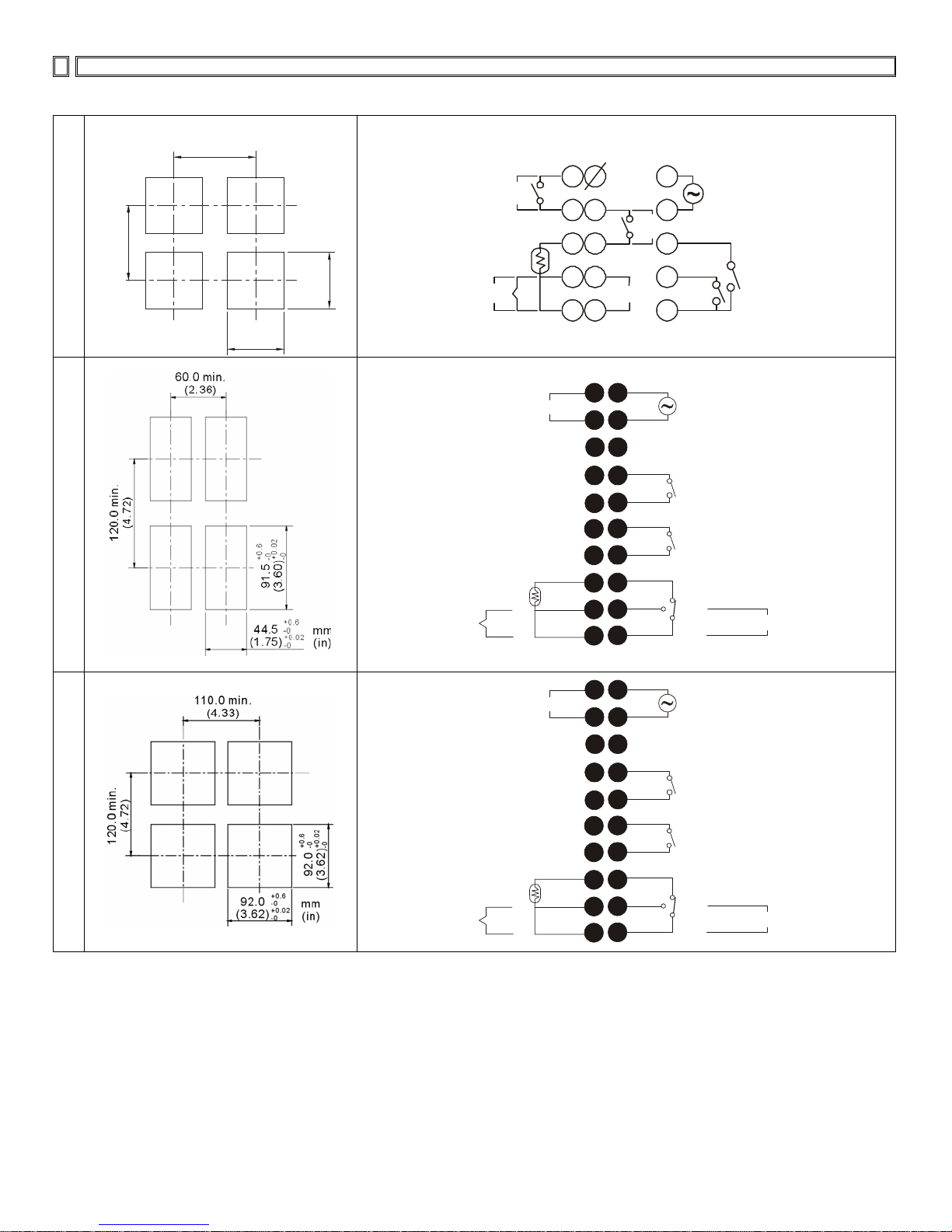
8 Plan Cutout and External Dimensions
Panel Cutout [dimensions are in mm (in.)]
Terminals Identification
65.0 min.
16C
(2.56)
.
n
)
i
6
m
3
.
0
.
2
(
0
6
+0.6
45.0
-0
+0.02
(1.77)
-0
6
.
0
+
mm
(in)
2
0
.
0
0
0
-
+
-
)
7
0
.
7
.
5
1
4
(
14V
DC
or
4~20mA
or
0~10V
RTD
+
IN
-
OUT1
-
+
COM
+
Tc
-
NO
1
6
2
7
3
8
4
9
5
10
OUT2/
ALM3
NO
14V
COM
DATA-
RS-485
DATA+
-
11
12
DC
13
+
14
15
L
AC 10 0 ~ 24 0V
50/60 Hz
5VA
N
ALM 2
ALM 1
3A
250Vac
COM
3A
250Vac
8C
4C
DATA+
RS-485
DATA-
1
2
3
4
11
12
13
14
L
N
COM
AC 100~240V
50~60Hz /5VA
3A 250Vac
15
5
ALM2
16
6
COM
17
7
ALM1
18
10
8
19
9
20
COM
1
11
RTD
+
Tc
or
-
DATA+
RS-485
2
DATA-
12
3
13
COM
4
14
NC
NO
L
N
3A 250Vac
5A 250Vac
-
DC 4~20mA
AC 100~240V
50~60Hz /5VA
14Vdc
+
3A 250Vac
15
5
ALM2
16
6
COM
17
7
ALM1
18
10
8
19
9
20
COM
RTD
+
Tc
or
-
NC
NO
3A 250Vac
5A 250Vac
DC 4~20mA
-
14Vdc
+
Page 15
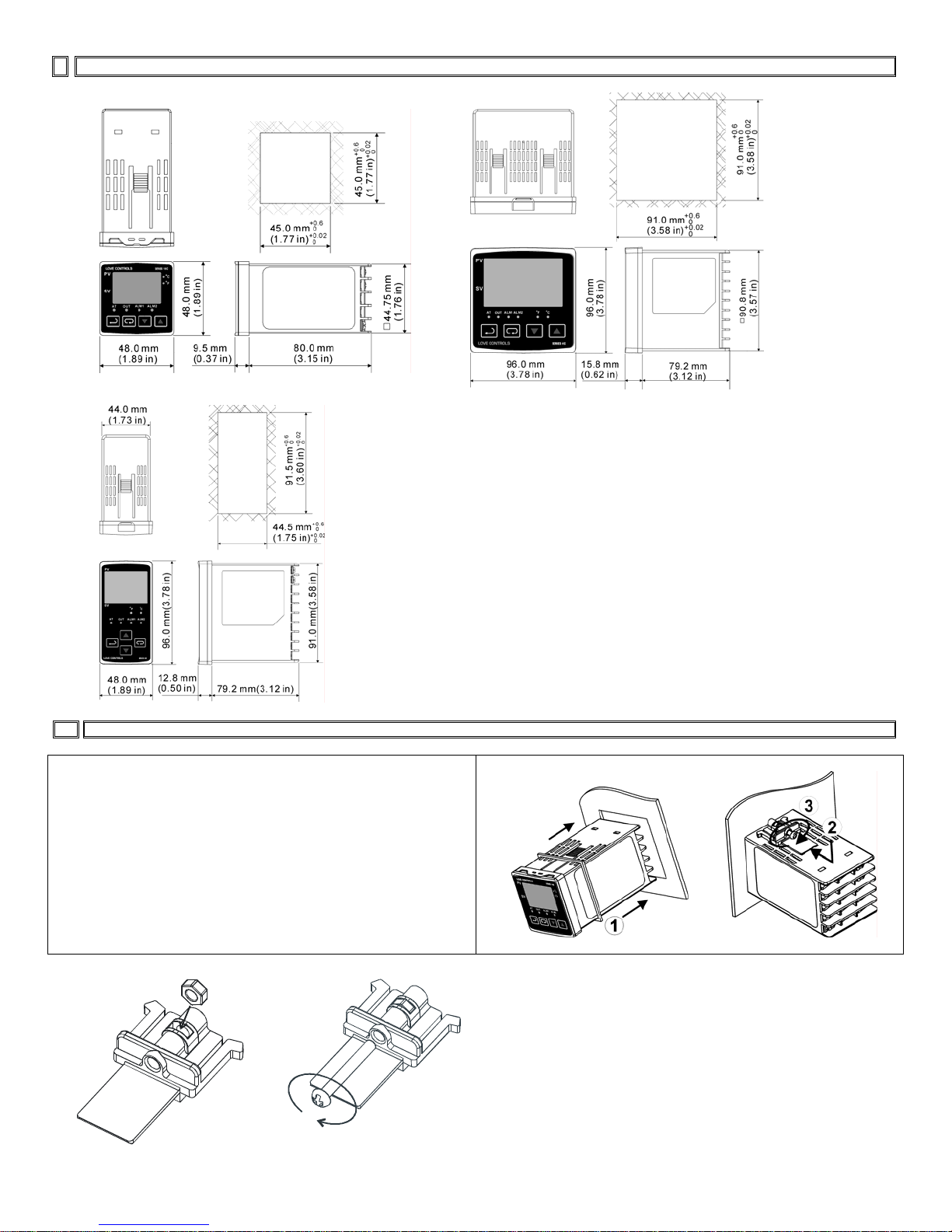
9 External Dimensions
g
Dimensions are in millimeter (inch)
16C
4C
8C
10 Mountin
Mounting Method
16C/8C/4C Mounting Method:
Step 1: Insert the controller through the panel cutout.
Step 2: Insert the mounting bracket into the mounting groove at
the top and bottom of the controller
Step 3: Push the mounting bracket forward until the bracket stops
at panel wall.
Step 4: Insert and tighten screws on bracket to secure the
controller in place. (The screw torque should be 0.8kgf-cm to
1.5kgf-cm)
Mounting Bracket Installation
Page 16

Page 17
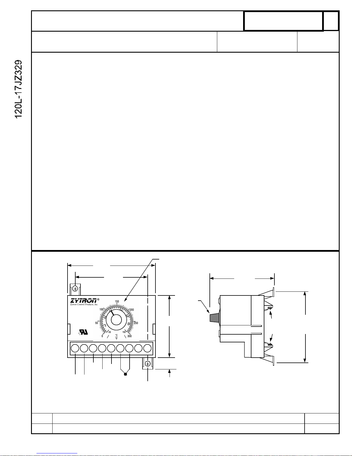
PRODUCT SPECIFICATION SHEET
MODEL:
120L-17JZ329
REV:
-
DESCRIPTION:
DIN Rail/Surface Mtg. Temp Limit Controller
CUSTOMER PN:
Process Heating
DATE:
10/17/06
Input Voltage : 115VAC ±15%, 50/60Hz, 3VA Max.
Control Output: SPDT Relay, N.O. contacts rated 8 Amps Res. 240VAC, 100,000 cycles
Control Mode: Relay de-energizes on temperature rise (N.O. contacts open).
Control Action: Latching with manual reset (Reset terminals open) or On-Off with 2oF Hyst. (Reset
terminals shorted) .
Manual Reset: Cycle power off & on or momentarily short Reset terminals with N.O. momentary
switch (customer supplied). .
Set Point Range: 0 to 600oF
Setpoint Adj.: Local SP pot with dual oF/oC graduated scales
Sensor Type: “J” Thermocouple
Compensation: Automatic cold junction compensation
Control Stability: Typically better than ±5mV/oF ambient and .01% of span/% rated line voltage
Set Point Accuracy: ±3% of FS maximum at 25oC and rated line voltage
Sensor Failure Prot: Contacts open for thermocouple break
Amb. Oper. Temp: 0 to 55oC (32 to 131oF )
MECHANICAL
Enclosure Material: Noryl, Black color
Field Terminations: Screw termininals with wire clamping plates and touch safe shield.
Mounting: 35mm DIN rail and surface mounting base
AGENCY APPROVALS UL 873 & CUL per CSA C22.2 No. 24 File #E105669
DIMENSIONS:
3.30”
2.50”
Horz. Panel
Mtg. Centers
Temperature
Controller
120L
US
C
1
2 3 4 5 6 7 8 9
N.C.
L1 L2
115VAC
50/60Hz
Input Volts
LTR DESCRIPTION DATE
COM
N.O.
Relay
Output
- +
TC
Sensor
Scale shown for reference
only. Actual scale
graduations depend on
SP range above.
Set Point
Adjust
2.53”
.387”
2.75”
Max.
35mm
DIN Rail
3.00”
Vert. Panel
Mtg.Centers
ZYTRON CONTROL PRODUCTS, INC. 20 Lexington Ave. , Trenton, NJ 08618
Page 18

Page 19
1
Instruction
Bulletin
Boletín de
instrucciones
Directives
d'utilisation
39000-285-01D
01/2005
Huntington, IN USA
Industrial Control Transformer
Transformador de control industrial
Transformateur de contrôle industriel
Replaces / Reemplaza / Remplace 39000-285-01C 02/1997
Class
Clase
Classe
Type
Tipo
Type
9070 T, TF
Retain for future use. / Conservar para uso futuro. / À conserver pour usage ultérieur.
*
RECEIVING RECIBO RÉCEPTION
Inspect the transformer for damage.
If damaged, notify and file a claim
with the carrier. Contact the supplier
for repair or replacement.
Realice una inspección visual del
transformador para ver si encuentra
daños. Si ha encontrado daños, notifique a
la compañía de transportes y presente una
reclamación. Comuníquese con el
proveedor para obtener detalles sobre la
reparación o sustitución del equipo.
Inspecter le transformateur pour
rechercher les dommages. En cas de
dommage, prière d’aviser l’entreprise de
transport et de faire une déclaration
auprès de celle-ci. Contacter le fournisseur
pour les réparations ou le remplacement.
PRECAUTIONS PRECAUCIONES PRÉCAUTIONS
1. On the nameplate, verify that the
transformer kVA and voltage are
correct for the line and load.
1. Consulte la placa de datos y verifique
que los kVA y tensión del
transformador sean los correctos para
la línea y carga.
1. Sur la plaque signalétique, vérifier si
les kVA et la tension du transf ormateur
sont corrects pour la ligne et la charge.
Continued on next page Continúa en la siguiente página Page suivante
DANGER / PELIGRO / DANGER
HAZARD OF ELECTRIC SHOCK,
EXPLOSION, OR ARC FLASH
• Apply appropriate personal
protective equipment (PPE) and
follow safe electrical work
practices. See NFPA 70E.
• This equipment must only be
installed and serviced by qualified
electrical personnel in
accordance with the National
Electrical Code® (NEC®) and any
other applicable codes or
standards.
• Turn off all power supplying this
equipment before working on or
inside equipment.
• Always use a properly rated
voltage sensing device to confirm
power is off.
• Replace all devices, doors and
covers before turning on power to
this equipment.
PELIGRO DE DESCARGA ELÉCTRICA,
EXPLOSIÓN O DESTELLO POR
ARQUEO
• Utilice equipo de protección personal
(EPP) apropiado y siga las prácticas de
seguridad eléctrica establecidas por su
Compañía, consulte la norma 70E de
NFPA.
• Solamente el personal eléctrico
especializado deberá instala r y prestar
servicio de mantenimiento a este equipo
de acuerdo con las normas del Código
nacional eléctrico de los EUA (NEC
®
) o
NOM-001-SEDE así como con cualquier
otra norma y código local
correspondiente.
• Desenergice el equipo antes de realizar
cualquier trabajo en él.
• Siempre utilice un dispositivo detector de
tensión nominal adecuado para
confirmar la desenergización del equipo.
• Vuelva a colocar todos los dispositivos,
las puertas y las cubiertas antes de
volver a energizar el equipo.
RISQUE D'ÉLECTROCUTION,
D'EXPLOSION OU D'ÉCLAIR D'ARC
• Portez un équipement de protection
personnelle (ÉPP) approprié et
observez les méthodes de travail
électrique sécuritaire. Voir NFPA 70E.
• Seul un personnel qualifié doit effectuer
l'installation et l'entretien de cet appareil
conformément au Code National de
l’Électricité (NEC
®
; É.-U.) et tout autre
code et norme applicables.
• Coupez l'alimentation de l'appareil
avant d'y travailler.
• Utilisez toujours un dispositif de
détection de tension ayant une valeur
nominale appropriée pour s'assurer
que l'alimentation est coupée.
• Replacez tous les dispositifs, les portes
et les couvercles avant de mettre
l'appareil sous tension.
Failure to follow these
instructions will result in death or
serious injury.
El incumplimiento de estas
instrucciones podrá causar la muerte o
lesiones serias.
Si ces directives ne sont pas
respectées, cela entraînera la mort ou
des blessures graves.
Page 20
Industrial Control Transformer
Transformador de control industrial 39000-285-01D
Transformateur de contrôle industriel 01/2005
© 1997–2005 Schneider Electric All Rights Reserved / Reservados todos los derechos / Tous droits réservés2
2. Install the transformer only in a
well-ventilated area that is free
from explosive or corrosive
gases, vapor, or excessive dust,
dirt, and moisture.
2. Instale el transformador sólo en un área
bien ventilada libre de gases e xplosivos
y corrosivos, va por o de masia do polvo,
suciedad y humedad.
2. Installer le transformateur seulement
dans une zone bien ventilée,
dépourvue de gaz ou de vapeur
explosif ou corrodant, ou de poussière,
de saletés et d’humidité excessives.
3. Ensure a free flow of air around
the transformer. Do not exceed
surrounding air temperature of
40° C (104° F).
3. Asegúrese de que circule el aire
alrededor del transformador y de que
no exceda la temperatura ambiente de
40° C (104° F).
3. Assurer une circulation libre de l’air
autour du transformateur. Ne pas
dépasser une température ambiante
de 40° C (104° F).
4. Use sufficient mounting hardware
to support the weight of the
transformer.
4. Utilice suficiente herrajes de montaje
para soportar el peso del
transformador.
4. Utiliser la quincaillerie de montage
suffisante pour supporter le poids du
transformateur.
PROTECTION PROTECCIÓN PROTECTION
Use fuses or circuit breakers in
accordance with Article 450 of the
National Electrical Code
®
(NEC®)
and any other applicable codes and
standards.
Utilice los fusibles o interruptores
automáticos necesarios para cumplir con los
requisitos del artículo 450 del Código
nacional eléctrico de EUA (NEC®) o
NOM-001-SEDE así como con otras normas
y códigos locales correspondientes.
Utiliser les fusibles ou les disjoncteurs
conformément à l’article 450 du Code
national de l'électricité (NEC
®
; É.-U.) et à
tout autre code ou norme applicable.
— For Type TF fusing, use only
Class CC rejection fuses on
the primary .
— Para la unidades tipo TF, utilice
sólo fusibles de rechazo clase CC
en el primario.
— Pour les unité s type T F, utiliser
uniquement des fusibles class CC
avec dispositif de rejet sur le primaire.
— If high voltage transients are
possible, use appropriate
surge suppression.
— Utilice supresores de transitorios
apropiados si existe la posibilidad
de sobretensiones transitorias.
— Si des tensions transitoires élevées
sont possibles, utiliser une
suppression de surtension
appropriée.
ACCESSORIES ACCESORIOS ACCESSOIRES
To meet European Normalized (EN)
Standards, use terminal covers (not
included). Refer to the transformer
section in the Schneider Electric
Digest, and call 1-888-778-2733 for
accessory information.
Para cumplir con las normas europeas
(EN), utilice las cubiertas de terminales
(no provistas). Consulte la sección de
transformadores en el Compendiado de
Schneider Electric y llame al
1-888-778-2733 (en los EUA) para obtener
información sobre los accesorios.
Pour satisfaire aux normes européennes
(NE), utiliser des couvercles de bornes
(non fournis). Se reporter à la section des
transformateurs dans le Digest Schneider
Electric, et appeler le 1-888-778-2733
(É.-U.) pour obtenir des informations
concernant les accessoires.
CONNECTION AND INSTALLATION CONEXIÓN E INSTALACIÓN CONNEXION ET INSTALLATION
DANGER / PELIGRO / DANGER
HAZARDOUS VOLTAGE
Turn off power before installing or
servicing.
TENSIÓN PELIGROSA
Desconecte la alimentación antes de
instalar o prestarle servicio.
TENSION DANGEREUSE
Coupez l’alimentation avant d’installer ou
de procéder à l’entretien.
Failure to follow this instruction
will result in death or serious
injury.
El incumplimiento de esta instrucción
podrá causar la muerte o lesiones
serias.
Si cette directive n’est pas respectée,
cela entraînera la mort ou des
blessures graves.
Page 21

Industrial Control Transformer
39000-285-01D Transformador de control industrial
01/2005 Transformateur de contrôle industriel
© 1997–2005 Schneider Electric All Rights Reserved / Reservados todos los derechos / T ous droits réservés
3
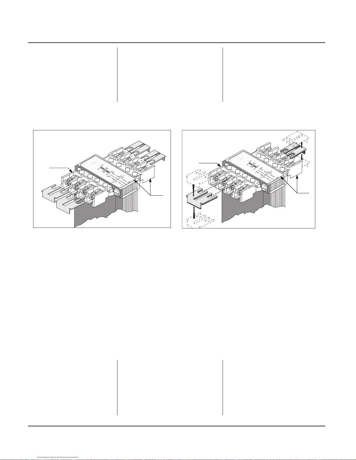
1. If necessary, install jumpers to
obtain input and/or output
voltages. If windings are tapped,
do not use jumpers.
1. Si es necesario, instale puentes de
conexión para obtener tensiones de
entrada y/o salida. Si los devanados
tienen derivaciones, no utilice puentes
de conexión.
1. Si nécessaire, installer des cavaliers
pour obtenir les tensions d’entrée ou
de sortie. Si les enroulements sont
munis de prises, ne pas utiliser de
cavaliers.
— Figure 1 on page 4 shows a
typical parallel connection to
obtain the lower of the two
possible voltages. On the
primary side, connect one
jumper to H1 and H3 and one
to H2 and H4. On the
secondary side, connect one
jumper to X2 and X4 and one
to X1 and X3.
— La figura 1 en la página 4 muestra
una conexión paralela típica par a
obtener la tensión más baja posible
de las dos. En el lado del primario,
conecte un puente a H1 y H3 y el
otro puente a H2 y H4. En el lado
del secundario, conecte un puente a
X2 y X4 y el otro puente a X1 y X3.
— La figure 1 à la page 4 indique la
connexion parallèle typique pour
obtenir la tension la plus faible des
deux tensions possibles. Sur le
côté primaire, connecter un cavalier
entre H1 et H3 et un autre entre H2
et H4. Sur le côté secondaire,
connecter un cavalier entre X2 et
X4 et un autre entre X1 et X3.
— Figure 2 on page 4 shows
typical series connection to
obtain the higher of the two
possible voltages. On primary
side, connect both jumpers to
H2 and H3. On secondary
side, connect both jumpers to
X2 and X3. See the
nameplate wiring diagram for
connections.
— La figura 2 en la página 4 muestra
una conexión en serie típica para
obtener la tensión más alta posible
de las dos. En el lado del primario,
conecte ambos puentes a H2 y H3.
En el lado del secundario, conecte
ambos puentes a X2 y X3.
Consulte el diagrama de alambrado
en la placa de datos para realizar
las conexiones.
— La figure 2 à la page 4 indique la
connexion en série typique pour
obtenir la tension la plus élevée des
deux tensions possibles. Sur le
côté primaire, connecter les deux
cavaliers entre H 2 et H3 . Sur le
côté secondaire, connecter les
deux cavaliers entre X2 et X3. Voir
le schéma de câblage de la plaque
signalétique pour obtenir les
connexions.
2. Connect only the primary
according to the nameplate
wiring diagram (A).
2. Conecte solamente el primario según
el diagrama de alambrado en la placa
de datos (A).
2. Connecter seulement le primaire
conformément au schéma de câblage
de la plaque signalétique (A).
3. Energize the transformer.
Measure the secondary voltage
to ensure transformer voltages
are correct for the load.
3. Energice el transformador. Mida la
tensión secundaria y asegúrese de que
las tensiones del transformador sean
las correctas para la carga.
3. Mettre le transformateur sous tension.
Mesurer la tension secondaire pour
s’assurer que les tensions du
transformateur correspondent à la
charge.
4. Turn off the primary supply, and
connect the load to the
secondary terminals (B). All
terminals are not always used.
See the nameplate wiring
diagram.
4. Desconecte la fuente de alimentación
del primario y conecte la carga a las
terminales del secundario (B). No
siempre se usan todas las terminales.
Consulte el diagrama de alambrado en
la placa de datos.
4. Couper l’alimentation primaire et
connecter la charge aux bornes
secondaires (B). Les bornes ne sont
pas toujours toutes utilisées. Voir le
schéma de câblage de la plaque
signalétique.
5. Tighten all unused screws.
Torque the remaining screws
as follows:
5. Apriete todos los tornillos sin usar.
Apriete el resto de los tornillos de la
siguiente manera:
5. Serrer toutes les vis non utilisées.
Serrer les autres vis aux couples
suivants :
— 6–32 screw
7–9 lbs-in (0.8–1.0 N•m)
— Tornillo 6–32
0,8–1,0 N•m (7–9 lbs-pulg)
— Vis 6–32
0,8 à 1,0 N•m (7 à 9 lb-po)
— 8–32 screw
14–16 lb-in (1.6–1.8 N•m)
— Tornillo 8–32
1,6–1,8 N•m (14–16 lbs-pulg)
— Vis 8–32
1,6 à 1,8 N•m (14 à 16 lb-po)
— 10–24 screw
17–19 lb-in (1.9–2.2 N•m)
— Tornillo 10–24
1,9–2,2 N•m (17–19 lbs-pulg)
— Vis 10–24
1,9 à 2,2 N•m (17 à 19 lb-po)
6. If applicable, install the covers. 6. Si fuese aplicable, instale las cubiertas. 6. Le cas échéant, inst al ler les cou vercles.
7. Energize the transformer. 7. Energice el transformador. 7. Mettre le transformateur sous tension.
Page 22
Industrial Control Transformer
Transformador de control industrial 39000-285-01D
Transformateur de contrôle industriel 01/2005
Electrical equipment should be installed,
operated, serviced, and maintained only by
qualified personnel. No responsibility is assumed
by Schneider Electric for an y con seq uen ces
arising out of the use of this material.
Solamente el personal especializado deberá instalar,
hacer funcionar y prestar servicios de mantenimiento
al equipo eléctrico. Schneider Electric no asume
responsabilidad alguna por las consecuencias
emergentes de la utilización de este material.
Seul un personnel qualifié doit effectuer l’installation,
l’utilisation, l’entretien et la maintenance du matériel
électrique. Schneider Electric n’assume aucune
responsabilité des conséquences éventuelles
découlant de l’utilisation de cette documentation.
Schneider Electric USA
6 Commercial Road
Huntington, IN 46750 USA
1-888-SquareD (1-888-778-2733)
www.us.SquareD.com
Importado en México por:
Schneider Electric México, S.A. de C.V.
Calz. J. Rojo Gómez 1121-A
Col. Gpe. del Moral 09300 México, D.F.
Tel. 55-5804-5000
www.schneider-electric.com.mx
Schneider Electric Canada
19 Waterman Avenue, M4B 1 Y2
Toronto, Ontario
1-800-565-6699
www.schneider-electric.ca
© 1997–2005 Schneider Electric
All Rights Reserved / Reservados todos los derechos / Tous droi ts réservés
* a brand of Schneider Electric. / una marca de Schneider Electric. /
une marque de Schneider Electric.
MAINTENANCE SERVICIO DE MANTENIMIENTO ENTRETIEN
1. De-energize the transformer. 1. Desenergice el transformador. 1. Mettre le transformateur hors tension.
2. Check for loose connections and
wiring, or lead deterioration.
Tighten, insulate, or replace
where necessary.
2. Realice una inspección para ver si
encuentra conexiones y cables sueltos, o
conductores dañados. Apriete las
conexiones, aísle o reemplace los ca bles
o conductores que sean necesarios.
2. Rechercher les connexions et les
câbles desserrés, ou les conducteurs
endommagés. Serrer les connexions,
isoler ou remplacer les câbles ou
conducteurs lorsque nécessaire.
Figure / Figura / Figure 1 : Typical parallel connection /
Conexión paralela típica /
Connexion parallèle typique
Figure / Figura / Figure 2 : Typical series connection /
Conexión en serie típica /
Connexion en série typique
H1
X4
X2
X3
X1
H3
H2
H4
H1-H3
H2-H4
X2-X4
X1-X3
B
A
H1
H
3
X4
X2
UL/CSA
50/60 Hz
0.25 kVA
9070T250D31
EN
61558
50/60 Hz
0.16 kVA
C
L
O
C
K
D
A
T
E
C
L
AS
S
/
C
L
ASE/C
L
AS
SE 130
˚C
H
1
X2
X1
H
3
H
2
H
4
X4
X3
T
250D
31
H
2
H4
X3
X1
220 230 240
440 460 480
H
1
H
3 H2 H4
H1 H3 H2 H4
X
2
X
4
X3
X1
11
0 115
1
2
0
X2
X
4
X3
X1
220 230 240
H1
X4
X2
X3
X1
H3
H2
H4
X2-X3
H2-H3
B
H1
H3
X4
X2
UL/CSA
50/60 Hz
0.25 kVA
9070T250D31
EN 6155
8
50/60 Hz
0.16
kVA
C
L
O
C
K
D
A
T
E
C
L
AS
S
/
C
L
ASE/C
L
AS
S
E 130
˚C
H
1
X2
X
1
H
3
H
2
H
4
X4
X3
H2
H4
X3
X1
220 230 240
440
4
60
480
H
1
H3
H
2
H4
H1 H3 H2 H4
X2
X
4
X3
X1
110 115
1
2
0
X2
X
4
X3
X1
220
230 240
T
250D
31
A
Page 23

Notes
7
Page 24

8
 Loading...