

PROCESS CENTER LRF-2000H User Manual
Process Center AB
Skogsbrynsvägen 8 C
236 31 Höllviken
040 452900 info@processcenter.se
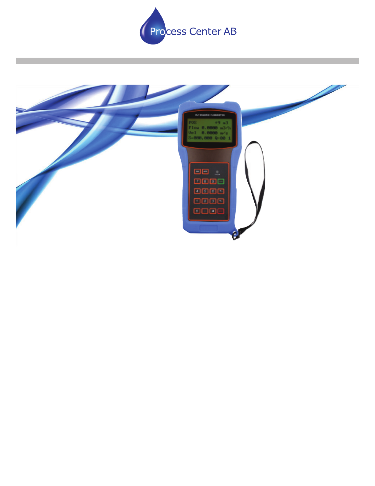
LRF-2000H Ultraljud med Clamp On sensorer
www.processcenter.se
Manual

Process Center AB
Skogsbrynsvägen 8 C
236 31 Höllviken
040 452900 info@processcenter.se
LRF-2000H Ultraljud med Clamp On sensorer
www.processcenter.se
Your flow measurement expert www.ultrasonicscn.com
Contents
1. Introduction ...................................................................................................................................... 1
§1.1 Preface .................................................................................................................................. 1
§1.2 Main Features ....................................................................................................................... 1
§1.3 Principle of Measurement .................................................................................................... 2
§1.4 Packing List (Standard Configuration) ................................................................................ 2
§1.5 Front view............................................................................................................................. 3
§1.6 Typical Applications ............................................................................................................. 4
§1.7 Data Integrity and Built-in Time-Keeper ............................................................................. 4
§1.8 Product Identification ........................................................................................................... 4
§1.9 Basic Technical Data ............................................................................................................ 4
2. Starting Measurement ....................................................................................................................... 6
§2.1 Built-in Battery ..................................................................................................................... 6
§2.2 Power On .............................................................................................................................. 6
§2.3 Keypad .................................................................................................................................. 7
§2.4 Menu Windows .................................................................................................................... 7
§2.5 Steps to Configure the Parameters ....................................................................................... 8
§2.6 Transducers Mounting Allocation ...................................................................................... 10
§2.7 Transducers Installation ..................................................................................................... 11
§2.7.1 Transducers Spacing .......................................................................................... 11
§2.7.2 V-method Installation .......................................................................................... 11
§2.7.3 Z-method Installation .......................................................................................... 13
§2.7.4 W-method Installation ......................................................................................... 13
§2.7.5 N-method Installation .......................................................................................... 13
§2.8 Installation Checkup ........................................................................................................... 14
§2.8.1 Signal Strength .................................................................................................... 14
§2.8.2 Signal Quality ....................................................................................................... 14
§2.8.3 Total Transit Time and Delta Time .................................................................... 14
§2.8.4 Time Ratio between the Measured Total Transit Time and the Calculated
Time ................................................................................................................................... 15
3. Menu Window Details .................................................................................................................... 16
§3.1 Menu Windows Arrangement ............................................................................................ 16
§3.2 Menu Window Details ........................................................................................................ 16

Process Center AB
Skogsbrynsvägen 8 C
236 31 Höllviken
040 452900 info@processcenter.se
LRF-2000H Ultraljud med Clamp On sensorer
www.processcenter.se
Your flow measurement expert www.ultrasonicscn.com
4. How To ........................................................................................................................................... 22
4.1 How to judge if the instrument works properly ................................................................... 22
4.2 How to judge the liquid flowing direction ........................................................................... 22
4.3 How to change between units systems ................................................................................. 23
4.4 How to select a required flow rate unit ................................................................................ 23
4.5 How to use the totalizer multiplier ....................................................................................... 23
4.6 How to open or shut the totalizers ....................................................................................... 24
4.7 How to reset the totalizers .................................................................................................... 24
4.8 How to restore the flow meter with default setups .............................................................. 24
4.9 How to use the damper ......................................................................................................... 24
4.10 How to use the zero-cutoff function ................................................................................... 25
4.11 How to setup a zero point ................................................................................................... 25
4.12 How to get a scale factor for calibration ............................................................................ 25
4.13 How to use the system locker............................................................................................. 26
4.14 How to use 4-20mA current loop output ............................................................................ 26
4.15 How to use the Frequency Output ...................................................................................... 27
4.16 How to use the Totalizer Pulse Output ............................................................................... 28
4.18 How to use the built-in Buzzer........................................................................................... 30
4.19 How to use the OCT output ............................................................................................... 30
4.20 How to modify the built-in calendar .................................................................................. 30
4.21 How to view the Date Totalizers ........................................................................................ 31
4.22 How to use the Working Timer .......................................................................................... 31
4.23 How to use the manual totalizer ......................................................................................... 31
4.24 How to know how long the battery will last ...................................................................... 31
4.25 How to check the ESN and other minor detail .................................................................. 32
4.26 How to use the data logger for scheduled output ............................................................... 32
4.27 How to output analogue voltage signal .............................................................................. 32
4.28 How to adjust the LCD display .......................................................................................... 32
4.29 How to use RS232/RS485? ................................................................................................ 33
4.30 How to use automatic amending function for offline compensation ................................. 33
4.31 How to use batch controller ............................................................................................... 33
4.32 How to adjust the analogue output ..................................................................................... 33
4.33 How to solidify the parameters .......................................................................................... 34
4.34 How to enter the parameters of user-type-transducer ........................................................ 34
4.35 How to use the circular display function ........................................................................... 34
4.36 How to enter into the linearity correcting? How to enter into the data? ........................... 35
4.37 How to save / restore frequently-used pipe parameters ..................................................... 37

Process Center AB
Skogsbrynsvägen 8 C
236 31 Höllviken
040 452900 info@processcenter.se
LRF-2000H Ultraljud med Clamp On sensorer
www.processcenter.se
Your flow measurement expert www.ultrasonicscn.com
5.Troubleshooting ............................................................................................................................... 3 8
§5.1 Power-on Error Displays and Counter-Measures .............................................................. 38
§5.2 Error Code and Counter-Measures..................................................................................... 38
§5.3 Other Problems and Solutions ............................................................................................ 39
6. Communication Protocol................................................................................................................ 42
§6. 1 General .............................................................................................................................. 4 2
§6.2 Interface Pin-out Definition ............................................................................................... 42
§6.3 the Protocol ........................................................................................................................ 42
§6.4 Protocol Prefix Usage ........................................................................................................ 43
§6.5 Codes for the Keypad ......................................................................................................... 44
7. Service ............................................................................................................................................ 46
§7.1 Service ................................................................................................................................ 46
§7.2 Software Upgrade Service .................................................................................................. 46
Appendix ............................................................................................................................................ 47
1. Sound speed data of liquid (unit: m/s) ................................................................................... 47
2. Sound speed data of solid (unit: m/s) ..................................................................................... 47
3. Sound speed in water at atmosphere pressure ........................................................................ 48

Process Center AB
Skogsbrynsvägen 8 C
236 31 Höllviken
040 452900 info@processcenter.se
LRF-2000H Ultraljud med Clamp On sensorer
www.processcenter.se
1
1. Introduction
§1.1 Preface
Welcome to the LRF-2000H ultrasonic flow meter that has been manufactured with patent
technologies and is equipped with more functions and advanced performance than our
previous versions.
The ultrasonic flow meter has been upgraded based on the previous ultrasonic flow meter
which is still the main product line of the company. The new Version retains most of the
excellent features and functions of the previous versions: the pulse measurement
technology, the ultrasonic igniting and the small signal receiving circuits etc. The main
improvements are made on the battery supply circuit and on the transmitting circuits. All
other circuits are simply integrated into this new version without major modifications, due to
the fact that we have already applied the most advanced measurement technologies and
attained a more reliable model of ultrasonic flow meter.
LRF-2000H flow meter incorporates the latest ICs manufactured from the famous
semiconductor manufacturers like Philips, Maxim, TI, Win bond, and Xilinx. The hardware
features the ease of operation, high accuracy and outstanding reliability, while the software
provides a very friendly user interface and much more functions. It employs a patent
balanced lower voltage multi-pulse igniting circuit which increases the anti-interference
ability magnificently so that the flow meter will work properly even in demanding industrial
environments such as those with power frequency transverter working nearby.
Other outstanding features:
----the signal receiving circuits feature self-adapting performance so as to ensure that the
user can easily operate the instrument without any adjustment.
----the built-in rechargeable Ni-MH battery can work continuously for more than 12 hours
without recharging.
The advanced circuit design, the integration of the latest semiconductors, the user-friendly
software interface both in English and Chinese languages and small-sized PCB board, all
these features combine to make the LRF-2000H ultrasonic flow meter the best and the
biggest seller on the Chinese market. Moreover, it is gaining more and more recognition on
the international flow meter market
§1.2 Main Features
* Large-screen LCD * Non-contacting measuring
* Built-in data-logger * Built-in rechargeable battery
* High accuracy measuring * Wide measuring range
Process Center AB
Skogsbrynsvägen 8 C
236 31 Höllviken
040 452900 info@processcenter.se
LRF-2000H Ultraljud med Clamp On sensorer
www.processcenter.se
2
Your flow measurement expert www.ultrasonicscn.com
* Small and light * RS-232 serial interface
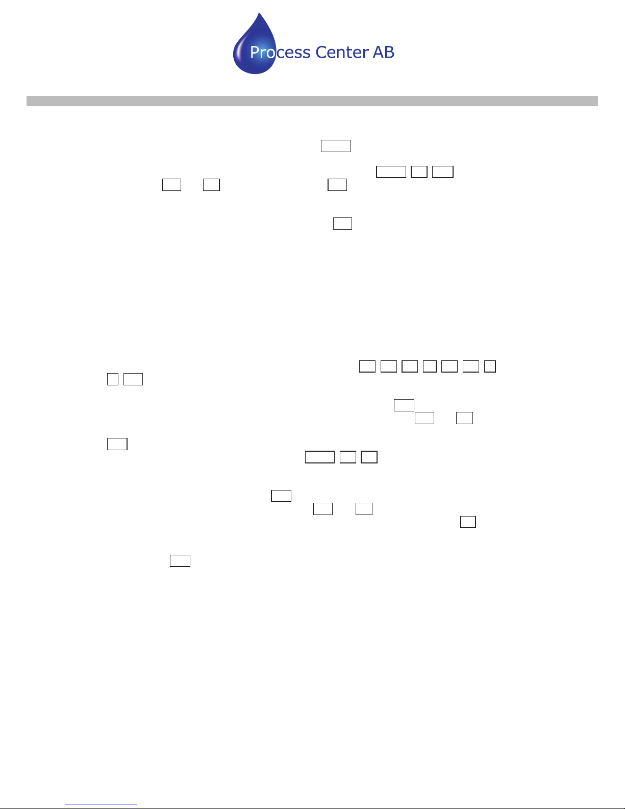
§1.3 Principle of Measurement
The LRF-2000H ultrasonic flow meter is designed to measure the fluid velocity of liquid
within a closed conduit. The transducers are a non-contacting, clamp-on type, which will
provide benefits of non-fouling operation and easy installation.
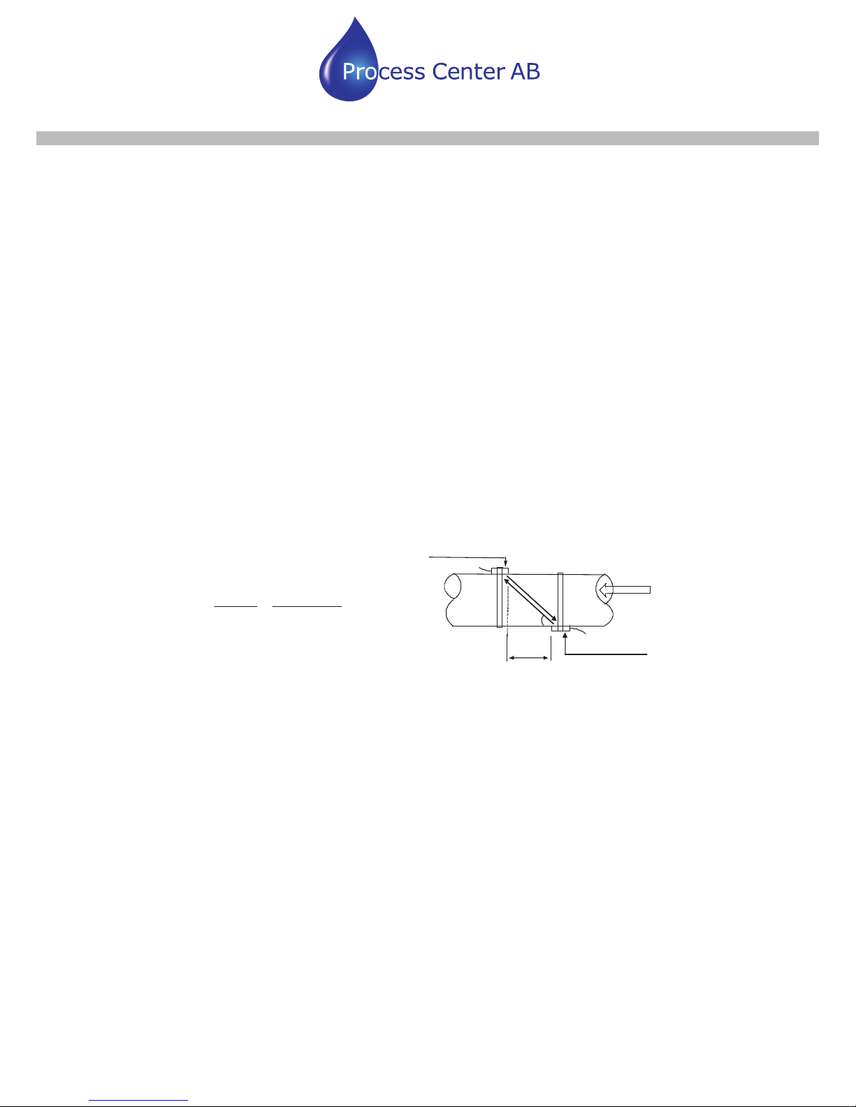
The LRF-2000H transit time flow meter utilizes two transducers that function as both
ultrasonic transmitters and receivers. The transducers are clamped on the outside of a
closed pipe at a specific distance from each other. The transducers can be mounted in
V-method where the sound transverses the pipe twice, or W-method where the sound
transverses the pipe four times, or in Z-method where the transducers are mounted on
opposite sides of the pipe and the sound crosses the pipe once. This selection of the
mounting method depends on pipe and liquid characteristics. The flow meter operates by
alternately transmitting and receiving a frequency modulated burst of sound energy
between the two transducers and measuring the transit time that it takes for sound to travel
between the two transducers. The difference in the transit time measured is directly and
exactly related to the velocity of the liquid in the pipe, show as follows:
Downstre am transducer
spacing
fl ow
Ups tream transducer
Tdown
Tup
Ƨ
downup
TT
TM D
V
x
'
u
T
2sin
Where
ș is the include angle to the flow direction
M is the travel times of the ultrasonic beam
D is the pipe diameter
Tup is the time for the beam from upstream transducer to the downstream one
Tdown is the time for the beam from downstream transducer to the upstream one
ǻT=Tup –Tdown
§1.4 Packing List (Standard Configuration)
Check up the packing list carefully before installing
Process Center AB
Skogsbrynsvägen 8 C
236 31 Höllviken
040 452900 info@processcenter.se
LRF-2000H Ultraljud med Clamp On sensorer
www.processcenter.se
3
Your flow measurement expert www.ultrasonicscn.com
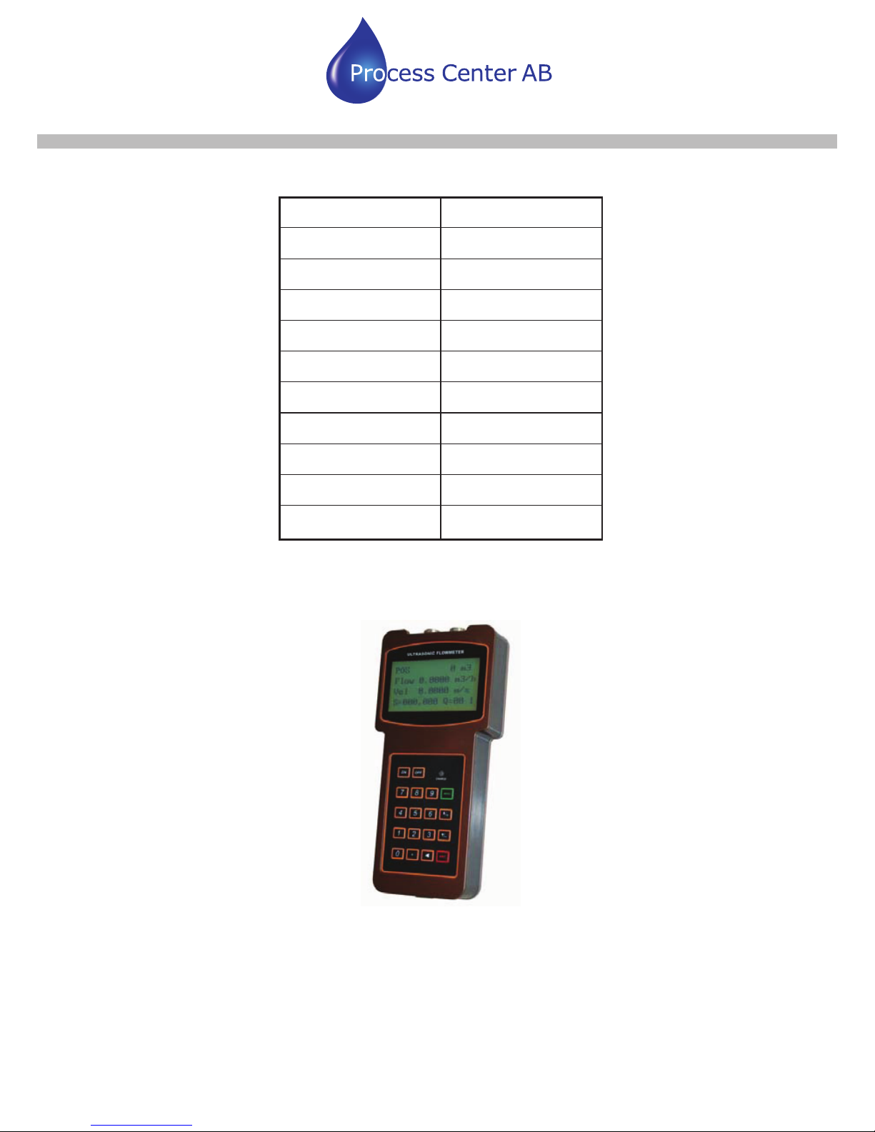
Name QTY (pcs)
Main Unit 1
Medium transducer 2
Ultrasonic signal cable 2
Data line 1
AC adapter 1
Coupling agent 1
Belt stretcher 2
Tape 1
User manual 1
Carrying case 1
§1.5 Front view

Process Center AB
Skogsbrynsvägen 8 C
236 31 Höllviken
040 452900 info@processcenter.se
LRF-2000H Ultraljud med Clamp On sensorer
www.processcenter.se
4
Your flow measurement expert www.ultrasonicscn.com
§1.6 Typical Applications
The LRF-2000H flow meter can be virtually applied to a wide range of measurements. A
variety of liquid applications can be accommodated: ultra-pure liquids, potable water,
chemicals, raw sewage, reclaimed water, cooling water, river water, plant effluent, etc.
Because the instrument and transducers are non-contacting and have no moving parts, the
flow meter can not be affected by system pressure, fouling or wear. Standard transducers
are rated to 110 ºC. Higher temperatures can be accommodated. For further information,
please consult the manufacturer for assistance.
§1.7 Data Integrity and Built-in Time-Keeper
All user-inputted configuration values are retained in the built-in non-volatile flash memory
that can store them for over 100 years, even if power is lost or turned off. Password
protection is provided to avoid inadvertent configuration changes or totalizer resets.
A time-keeper is integrated in the flow meter for the index of date totalizing and works as
the time base of flow accumulation. It keeps operating as long as the battery’s terminal
voltage is over 1.5V. In case of battery failure, the time-keeper will not keep running and it
will lose proper time values. The user must re-enter proper time values in case the battery
becomes totally exhausted. An improper time value affects no other functions but the date
totalizer.
§1.8 Product Identification
Each set of the LRF-2000H has a unique product identification or ESN written into the
software that can only be modified with a special tool by the manufacturer. In case of any
hardware failure, please provide this number which is located on menu window number
M61 when contacting the manufacture.
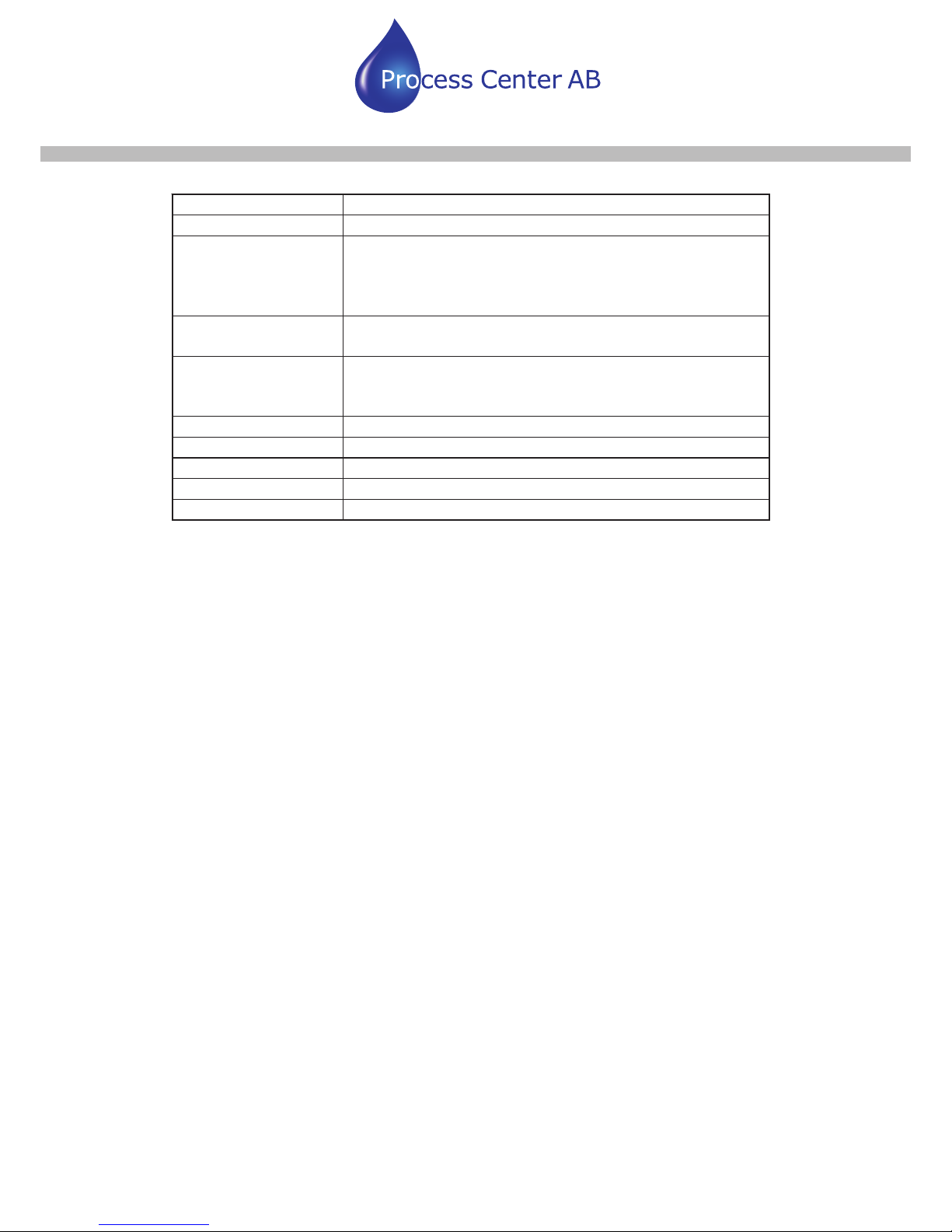
§1.9 Basic Technical Data
Linearity 0.5%
Repeatability 0.2%
Accuracy ±1% of reading at rates>0.2 mps
Response Time 0-999 seconds, user-configurable
Velocity ±32 m/s
Pipe Size 15mm-6000mm
Totalizer
7-digit totals for net, positive and negative flow
respectively
Liquid Types Virtually all liquids
Security Setup values Modification Lockout. Access code needs
Process Center AB
Skogsbrynsvägen 8 C
236 31 Höllviken
040 452900 info@processcenter.se
LRF-2000H Ultraljud med Clamp On sensorer
www.processcenter.se
5
Your flow measurement expert www.ultrasonicscn.com
unlocking
Display 4x8 Chinese characters or 4x16 English letters
Communication
Interface
RS-232, baud-rate: from 75 to 57600. Protocol made by
the manufacturer and compatible with that of the FUJI
ultrasonic flow meter. User protocols can be made by
user requirements
Transducer Cord
Length
Standard 5m x 2, optional 10m x 2
Power Supply
3 AAA built-in Ni-H batteries. When fully recharged it will
last over 12 hours of operation.
100V-240VAC for the charger
Data Logger Built-in data logger can store over 2000 lines of data
Manual Totalizer 7-digit press-key-to-go totalizer for calibration
Housing Material ABS
Case Size 210x90x30mm
Main unit Weight 500g with batteries

Process Center AB
Skogsbrynsvägen 8 C
236 31 Höllviken
040 452900 info@processcenter.se
LRF-2000H Ultraljud med Clamp On sensorer
www.processcenter.se
6
2. Starting Measurement
§2.1 Built-in Battery
The instrument can operate either from the built-in Ni-H rechargeable battery, which will
last over 12 hours of continuous operation when fully recharged, or from an external
AC/power supply from the battery charger.
The battery charging circuits employ a scheme of constant-current and constant-voltage. It
has a characteristic of fast charging at the beginning and very slow charging when the
battery approaches to full recharge. Generally, when the green LED starts coming on, the
battery would be nearly 95% recharged and when the red LED is off, the battery would be
98% recharged.
Since the charging current becomes tapered when the battery recharge is nearly
completed, i.e. the charging current becomes smaller and smaller, therefore, there should
be no over-recharging problem. That means the charging progress can last very long. The
charger can be connected to the handset all the time when an around-the-clock
measurement is required.
When fully recharged, the terminal voltage reaches around 4.25V. The terminal voltage is
displayed on window M07. When the battery is nearly consumed, the battery voltage drops
to below 3V. The user can obtain an approximate battery working time from the battery
voltage.
A software battery working time estimator is integrated in this instrument based on the
terminal voltage. Please note that the estimator may have relatively bigger errors in the
estimated working time, especially when the voltage is in the range of around 3.70 to -3.90
volt.
§2.2 Power On
Press the ON key to switch on the instrument and press the OFF to turn off the
p ower.
Once the flow meter is switched on, it will run a self diagnostic program, checking first the
hardware and then the software integrity. If there is any abnormality, corresponding error
messages will display.
Generally, there should be no display of error messages, and the flow meter will go to the
most commonly used Menu Window Number 01 (short for M01) to display the Velocity,
Flow Rate, Positive Totalizer, Signal Strength and Signal Quality, based on the pipe
parameters configured last time by the user or by the initial program.
Process Center AB
Skogsbrynsvägen 8 C
236 31 Höllviken
040 452900 info@processcenter.se
LRF-2000H Ultraljud med Clamp On sensorer
www.processcenter.se
7
Your flow measurement expert www.ultrasonicscn.com
The flow measurement program always operates in the background of the user interface.
This means the flow measurement will keep on running regardless of any user menu
window browsing or viewing. Only when the user enters new pipe parameters will the flow
eter change measurement to the new parameter changes. m
When new pipe parameters have been entered or when the power has been just switched
on, the flow meter will enter an adjusting mode to make the signals magnified with proper
amplification. By this step, the flow meter is going to find the best threshold of receiving
signal. The user will see the progress by the number 1, 2, or 3, which are indicated on the
right lower corner of the LCD display.
When the transducers have been adjusted on the pipe by the user, the flow meter will
re-adjust the signal automatically.
Any user-entered configuration value will be retained into the NVRAM of the flow meter,
until it is modified by the user.
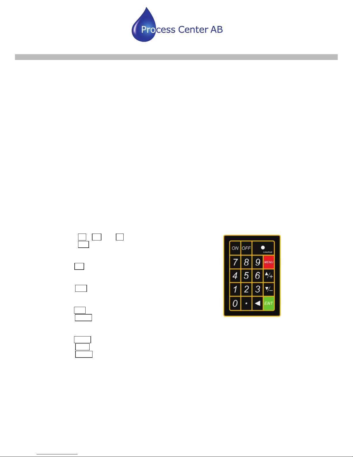
§2.3 Keypad
The keypad for the operation of the flow meter has 16+2 keys, as shown by the right
picture.
Keys 0 ~ 9 and . are keys to enter numbers
Key Ÿ/+ is the going UP key, when the user wants to go
to the upper menu window. It also works as the “+” key
when entering numbers
Key ź/- is the going DOWN key, when the user wants to
go down-sided menu window. It also works as the “–” key
when entering numbers.
Key Ż is backspace key, when the user wants go left or
wants backspace the left character that is located to the left
of the cursor.
Key ENT is the ENTER key for any inputting or selections.
Key MENU is the key for the direct menu window jump
over. Whenever the user wants to proceed to a certain
menu window, the user can press this key followed by 2-digit numbers.
The MENU key is shortened as the ‘M’ key afterward when referring to the menu windows.
The ON key is for the power on.
The OFF key is for the power off.
§2.4 Menu Windows
The user interface of this flow meter comprises about 100 different menu windows that are
numbered by M00, M01, M02 … M99.
Process Center AB
Skogsbrynsvägen 8 C
236 31 Höllviken
040 452900 info@processcenter.se
LRF-2000H Ultraljud med Clamp On sensorer
www.processcenter.se
8
Your flow measurement expert www.ultrasonicscn.com
There are 2 methods to enter certain menu window:
(1) Direct going/entering. The user can press the MENU key followed by two-digit number
keys. For example, the menu window M11 is for the entering of pipe outer diameter. The
display will go to the M11 menu window after the user presses MENU 1 1 .
(2) Pressing Ÿ/+ and ź/- keys. Each time of the Ÿ/+ key pressing will proceed to the
Lower - numbered menu window. For example, if the current window is on M12, the display
will go to the number M11 window after pressing the Ÿ/+ key.
There are three different types of menu windows:
(1) Menu windows for number entering, like M11 for the entering of pipe outer diameter.
(2) Menu windows for option selection/selecting options, like M14 for the selection of pipe
materials.
(3) Displaying windows only, like M00 to display Velocity, Flow Rate etc.
For number entering windows, the user can directly press the starting digit key when the
user is going to modify the value. For example, when the current window is on M11, and
the user is going to enter 219.2345 as the pipe outer diameter, the user can get the
numbers entered by pressing the following serial keys: 2 1 9 . 2 3 4
5 ENT.
For the option selection windows, the user should first press the ENT key to a selection
modification mode and then select the relevant options by pressing the Ÿ/+ and ź/- keys
or the digit keys to select the option with a number antecedent to the option. In the end, the
ENT key must be pressed to make the selection. For example, with menu window M14 for
the selection of pipe material selection, (the MENU 1 4 should be pressed first to
enter this menu window if the current menu window is on a different window. The pipe
material is stainless steel which has a number “1” antecedent to “stainless steel” on the
display, the user should first press the ENT key to enter into a selection modification mode,
then either make the selection by pressing the Ÿ/+ and ź/- keys to make the cursor on
the line that displays “1. Stainless Steel”, or make the selection by pressing the 1 key
directly.
Generally, the ENT key must be pressed to enter a modification mode. If the “Locked M47
Open’ message is indicated on the lowest line of the LCD display, it means the
modification operations is locked out. In such cases, the user should go to M47 to have the
instrument unlocked first before any further modification can be made.
§2.5 Steps to Configure the Parameters
The following parameters need to be configured for a proper measurement:
(1) Pipe outer diameter
(2) Pipe wall thickness
(3) Pipe materials (for non-standard pipe materials*, the sound speed for the material
must be configured too)
Process Center AB
Skogsbrynsvägen 8 C
236 31 Höllviken
040 452900 info@processcenter.se
LRF-2000H Ultraljud med Clamp On sensorer
www.processcenter.se
7
Your flow measurement expert www.ultrasonicscn.com
*Standard pipe materials and standard liquids refer to those with the sound
parameters that have already been programmed into software of the flow meter,
therefore there is no need to configure them
(4) Liner material and its sound speed and thickness, if there is any liner.
(5) Liquid type (for non-standard liquids, the sound speed of the liquid is also needed)
(6) Transducer type adapted to the flow meter. Generally the Standard M1 clamp-on
transducers will be the selected option.
(7) Transducer mounting methods (the V-method or Z-method is the common option)
(8) Check up the Space displayed on M25 and install the transducers accordingly.
For standard pipe materials and standard liquids, the following detailed step-by-step setup
is recommended.
(1) Press keys MENU 1 1 to enter M11 window to input the digits for the pipe outer
diameter, and then press ENT key.
(2) Press key ź/- to enter M12 window to input the digits for the pipe outer diameter and
then press ENT key.
(3) Press key ź/- to enter M14 window, and press ENT key to enter the option
selection mode. Use keys Ÿ/+ and ź/- to scroll up and down to the intended pipe
material, and then press ENT key.
(4) Press key ź/- to enter M16 window, press ENT key to enter the option selection
mode, use keys Ÿ/+ and ź/- to scroll up and down to the liner material, and then
press ENT key. Select “No Liner”, if there is no liner.
(5) Press key ź/- to enter M20 window, press ENT key to enter the option selection
mode, use keys Ÿ/+ and ź/- to scroll up and down to the proper liquid, and then
press ENT key.
(6) Press key ź/- to enter M23 window, press ENT key to enter the option selection
mode, use keys Ÿ/+ and ź/- to scroll up and down to the proper transducer type,
and then press ENT key.
(7) Press key ź/- to enter M24 window, press ENT key to enter the option selection
mode, use keys Ÿ/+ and ź/- to scroll up and down to the proper transducer
mounting method, and then press ENT key.
(8) Press key ź/- to enter M24 window to install the transducers on the pipe, and then
press ENT key to go to M01 for the results.
The first-time users may need some time to get familiar with the operation. However, the
user friendly interface of the instrument makes the operation quite easy and simple. Before
long, the user will configure the instrument with very little key pressing, since the interface
allows the user to go to the desired operation directly without any extra steps.
The following tips will facilitate the operation of this instrument.
(1) When the window display is between M00 to M09, press a number key x , the user
will go directly to the M0x window. For example, if the current window displays M01,
press 7 and the user will go to M07.
(2) When the window display is under M00 to M09, press the ENT key and the user will go

Process Center AB
Skogsbrynsvägen 8 C
236 31 Höllviken
040 452900 info@processcenter.se
LRF-2000H Ultraljud med Clamp On sensorer
www.processcenter.se
10
Your flow measurement expert www.ultrasonicscn.com
to
M90; press ENT key to return. Press the dot key to go to M11
(3) When the window display is under M25, press ENT key to go to M01.
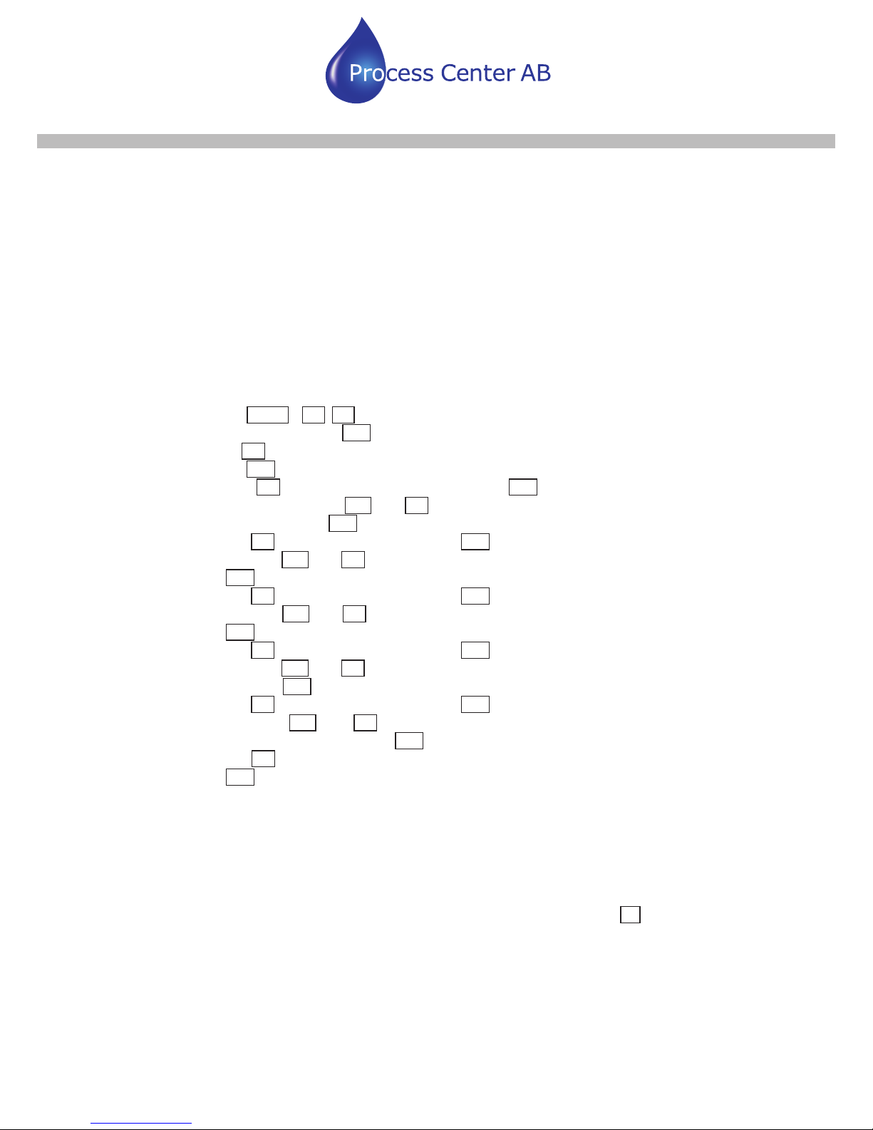
§2.6 Transducers Mounting Allocation
The first step in the installation process is the selection of an optimum location in order to
obtain a more accurate measurement. For this to be completed effectively, a basic
knowledge about the piping and its plumbing system would be advisable.
An optimum location would be defined as a straight pipe length full of liquid that is to be
measured. The piping can be in vertical or horizontal position. The following table shows
L up
L dn
L up
L dn
L up
L up
L u p
L d n
L d n
L d n
3LSLQ
J&RQILJXUDWLRQ
DQG
7UDQVGXFH
U3RVLWLR
Q
8SVWUHD
P
'LPHQVLRQ
'RZQVWUHD
P
'LPHQVLRQ
L dn
x Diam eters
L up
x D iam e ters
'
'
'
'
'
'
'
'
'
'
'
'
L u p
L d n
'
'
L u p
L d n
Examples of optimum locations.
Principles to selection of an optimum location
(1) Install the transducers on a longer length of the straight pipe. The longer the better,
and make sure that the pipe is completely full of liquid.
(2) Make sure that the temperature on the location does not exceed the range for the
transducers. Generally speaking, the closer to the room temperature, the better.
(3) Take the pipe fouling into consideration. Select a straight length of a relatively newer
pipe. If the condition is not satisfying, consider the fouling thickness as part of the liner
for a better result.
(4) Some pipes have a kind of plastic liner, and between the outer pipe and the liner there
may be a certain thickness difference that will prevent the ultrasonic waves from direct

Process Center AB
Skogsbrynsvägen 8 C
236 31 Höllviken
040 452900 info@processcenter.se
LRF-2000H Ultraljud med Clamp On sensorer
www.processcenter.se
11
Your flow measurement expert www.ultrasonicscn.com
traveling. Such conditions will make the measurement very difficult. Whenever
possible, try to avoid this kind of pipes. If impossible, try our plug-in transducers that
are installed permanently on the pipe by drilling holes on the pipe while liquid is running
inside.
§2.7 Transducers Installation
The transducers used by the LRF-2000 series ultrasonic flow meter are made of
piezoelectric crystals ceramic plate; both for transmitting and receiving ultrasonic signals
through the wall of liquid piping system. The measurement is realized by measuring the
traveling time difference of the ultrasonic signals. Since the difference is very small, the
spacing and the alignment of the transducers are critical factors to the accuracy of the
measurement and the performance of the system. Meticulous care should be taken for the
stallation of the transducers. in
Steps to the installation of the transducers
(1) Locate an optimum position where the straight pipe length is sufficient, and where
pipes are in a favorable condition, e.g., newer pipes with no rust and ease of
operation.
(2) Clean any dust and rust. For a better result, polishing the pipe with a sander is
strongly recommended.
(3) Apply adequate coupler to the spot where the transducers are to be installed and
leave no gap between the pipe surface and the transducers.
Extra care should be taken to avoid any sand or dust particles left between the pipe outer
urface and the transducers. s
To avoid gas bubbles inside the upper part of the pipe, the transducers should be installed
horizontally by the side of the pipe.
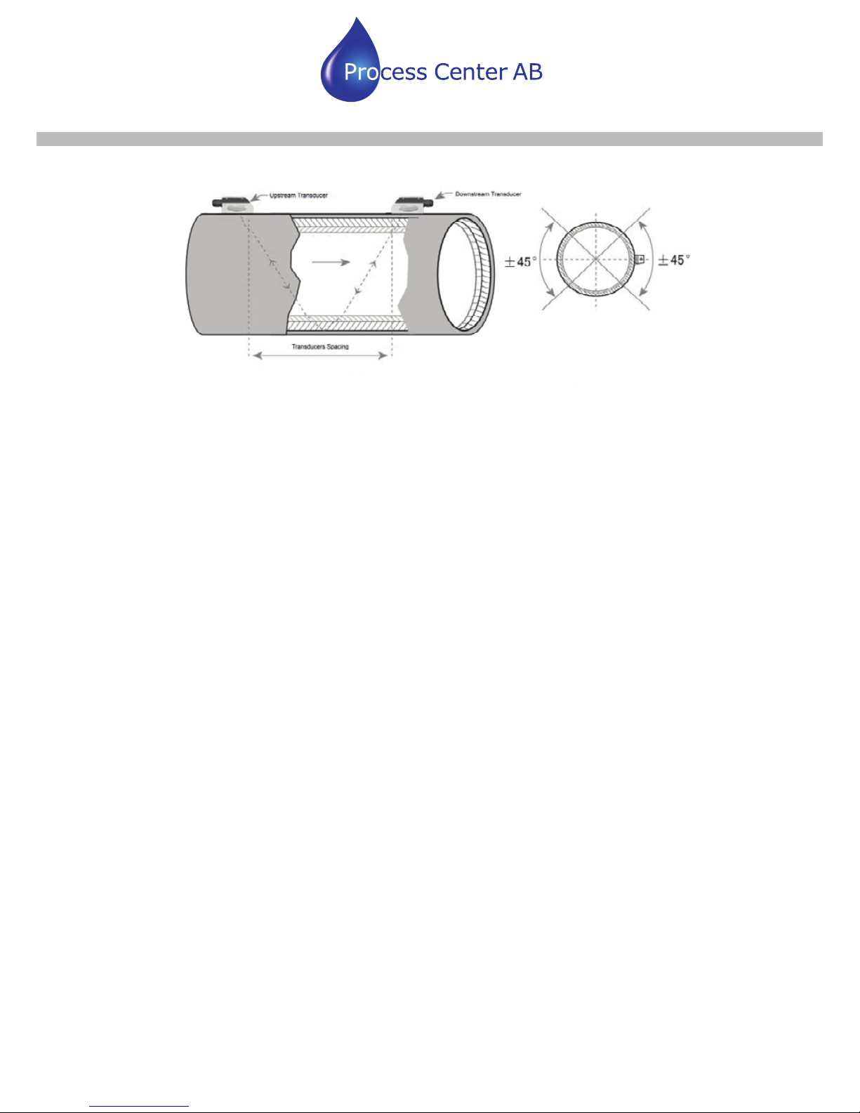
§2.7.1 Transducers Spacing
The spacing value shown on menu window M25 refers to the distance of inner spacing
between the two transducers. The actual transducers spacing should be as close as
possible to the spacing value.
§2.7.2 V-method Installation
V-method installation is the most widely mode for daily measurement with pipe inner
diameters ranging from 15 mm to 400 mm. It is also called reflective mode.
Process Center AB
Skogsbrynsvägen 8 C
236 31 Höllviken
040 452900 info@processcenter.se
LRF-2000H Ultraljud med Clamp On sensorer
www.processcenter.se
12
Your flow measurement expert www.ultrasonicscn.com
 Loading...