

Page 1

Page 2

Bedienungsanleitung
Operating Instructions
Mode d’emploi
Bewehrungs-Suchsystem
Rebar Detection System
Système de détection d’armatures
Modell S / SCANLOG
Page 3

Proceq SA
Ringstrasse 2
CH-8603 Schwerzenbach
Switzerland
Tel. +41-43-355-38-00
Fax +41-43-355-38-12
info-europe@proceq.com
Proceq USA, Inc.
117 Corporation Drive
Aliquippa, PA 15001
USA
Phone +1-724-512-0330
Fax +1-724-512-0331
info-usa@proceq.com
Proceq Asia Pte Ltd
12 New Industrial Road #02-02A
Singapore 536202
Republic of Singapore
Phone +65-6382-3966
Fax +65-6382-3307
info-asia@proceq.com
www.proceq.com
Subject to change without notice
.
Copyright © 2007 Proceq SA Switzerland 820 390 01 ver 05 2007
Page 4

Page 5

English
Page 6

Page 7

English
© 2007 Proceq SA Contents 1
Contents
1 Safety. . . . . . . . . . . . . . . . . . . . . . . . . . . . . . . . . . 2
General Information . . . . . . . . . . . . . . . . . . . . . . . 2
Liability. . . . . . . . . . . . . . . . . . . . . . . . . . . . . . . . . 2
Safety Regulations. . . . . . . . . . . . . . . . . . . . . . . . 2
Standards and Regulations Applied. . . . . . . . . . . 2
2 Product Description
. . . . . . . . . . . . . . . . . . . . . . 3
Model S (Basic Unit) . . . . . . . . . . . . . . . . . . . . . . 3
Model SCANLOG. . . . . . . . . . . . . . . . . . . . . . . . . 3
Universal Probe . . . . . . . . . . . . . . . . . . . . . . . . . . 4
ScanCar. . . . . . . . . . . . . . . . . . . . . . . . . . . . . . . . 5
3 Startup
. . . . . . . . . . . . . . . . . . . . . . . . . . . . . . . . . 6
Connecting the Components . . . . . . . . . . . . . . . . 6
Putting the Indicating device into Operation . . . . 6
4 Settings
. . . . . . . . . . . . . . . . . . . . . . . . . . . . . . . . 6
Bar Diameter . . . . . . . . . . . . . . . . . . . . . . . . . . . . 6
Object Number. . . . . . . . . . . . . . . . . . . . . . . . . . . 7
Limit Value . . . . . . . . . . . . . . . . . . . . . . . . . . . . . . 7
Corrections. . . . . . . . . . . . . . . . . . . . . . . . . . . . . . 7
Language. . . . . . . . . . . . . . . . . . . . . . . . . . . . . . . 8
Basic Setups . . . . . . . . . . . . . . . . . . . . . . . . . . . . 8
Data Output . . . . . . . . . . . . . . . . . . . . . . . . . . . . . 8
Measure with Statistics
. . . . . . . . . . . . . . . . . . . . 9
Scanning Bars . . . . . . . . . . . . . . . . . . . . . . . . . . . 9
Measure with Grid . . . . . . . . . . . . . . . . . . . . . . . . 9
5 Measuring Process
. . . . . . . . . . . . . . . . . . . . . . 9
Measure with Statistics . . . . . . . . . . . . . . . . . . . . 9
Detecting Insufficient Concrete Cover . . . . . . . . . 12
Determining the Bar Diameter . . . . . . . . . . . . . . . 13
Making Reinforcement Visible with CyberScan . . 14
Measure with Grid . . . . . . . . . . . . . . . . . . . . . . . . 17
Data Output . . . . . . . . . . . . . . . . . . . . . . . . . . . . . 20
6 Maintenance and Storage
. . . . . . . . . . . . . . . . . 22
Cleaning. . . . . . . . . . . . . . . . . . . . . . . . . . . . . . . . 22
Performance Check . . . . . . . . . . . . . . . . . . . . . . . 22
Storage. . . . . . . . . . . . . . . . . . . . . . . . . . . . . . . . . 22
7 Data
. . . . . . . . . . . . . . . . . . . . . . . . . . . . . . . . . . . 23
Form of Delivery. . . . . . . . . . . . . . . . . . . . . . . . . . 23
Accessories / Spare Parts . . . . . . . . . . . . . . . . . . 24
Technical Data . . . . . . . . . . . . . . . . . . . . . . . . . . . 24
Page 8
2 Safety © 2007 Proceq SA
1 Safety
1.1 General Information
1.1.1 Basic Information
The rebar locator complies with state-of-the-art technology and the recognized safety regulations.
Please read through these operating instructions carefully before initial startup.
1.1.2 Designated Use
The rebar locator is used for the non-destructive location
of rebars and for the measurement of concrete cover
and bar diameters.
1.2 Liability
Our «General Terms and Conditions of Sale and Delivery» apply in all cases. Warranty and liability claims
arising from personal injury and damage to property cannot be upheld if they are due to one or more of the following causes:
- Failure to use the rebar locator in accordance with its
designated use
- Incorrect startup and operation of the rebar locator
- Unauthorized structural modifications to the rebar
locator
- Serious damage resulting from the effects of foreign
bodies, accidents, vandalism and force majeure
1.3 Safety Regulations
1.3.1 Unauthorized Operators
Anyone who is not familiar with the operating instructions
must not use the rebar locator or must be supervised
when using it.
1.3.2 Safety Icons
The following icons are used in conjunction with all
important safety notes in these operating instructions.
Warning!
This note warns you about the risk of material
damage, financial loss and legal penalties
(e.g. loss of warranty rights, liability cases, etc.).
This denotes important information.
1.4 Standards and Regulations Applied
SIA 162 / DIN 1045 / DGZfP B2 / BS 1881: Part 204
Page 9

English
© 2007 Proceq SA Product Description 3
2 Product Description
2.1 Model S (Basic Unit)
The PROFOMETER 5+ rebar locator is a lightweight,
compact device for the non-destructive location of rebars
and for the measurement of concrete cover and bar
diameters.
The measuring method is based on the eddy-current
principle with pulse-induction.
Indicating device
Universal probe
Fig. 2.1 Model S
The basic unit can perform the following functions:
- Locating rebars
- Measuring concrete covers
- Storing individual cover values and statistical
evaluation
- Determining the bar diameters
2.2 Model SCANLOG
Indicating device
ScanCar
Universal probe
Fig. 2.2 Model SCANLOG
The SCANLOG rebar locator is identical to model S and
comprises the following additional functions:
- «CyberScan» function for displaying the concrete cover
- «Measure with Grid» function for grey-scale display of
the concrete cover
- ScanCar probe carriage with integral path measuring
device for scanning the rebars
- Storage areas for «CyberScan» and «Measure with
Grid» objects
In the case of both models, the data can be printed
directly on a printer connected to the indicating device or
transferred to a PC.
Page 10
4 Product Description © 2007 Proceq SA
2.3 Universal Probe
2.3.1 Functioning
The universal probe is designed to function in relation to
the direction. This means it reacts most sensitively to the
rebars parallel to its longitudinal axis, and least sensitively to the ones at right angles to its longitudinal axis.
For this reason the probe should be positioned parallel to
the bars to be tested and moved over them sideways for
scanning.
The probe has both a small and a large measuring
range. Use the ← and → keys to switch over between
the two measuring ranges. The active measuring range
is displayed in the measuring display (see Fig. 5.1).
The large measuring range should only be used if the
concrete cover is larger than is shown in the intersection
point of the curves in Fig. 2.4. If the bar diameter is 16
mm, this applies for a cover of approx. 60 mm.
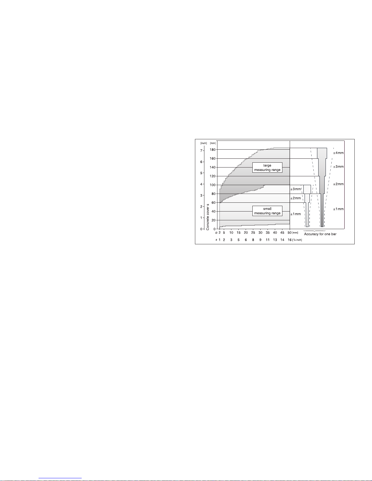
2.3.2 Measuring Ranges and Accuracy
Fig. 2.3 Measuring ranges and accuracy of the universal
probe
Key:
Ø : Bar diameter in mm
#: Bar diameter in «Bar size #»
---: Lowest accuracy limit required by the standard
BS 1881: Part 204: ±2 mm or ±5 %
PROFOMETER 5+ measures up to 50 % more accurately than required by this standard.
The size of the two measuring ranges of the universal
probe depends on the bar diameters. The accuracy of
the concrete cover indication refers to individual bars.
See also Fig. 2.4.
Page 11

English
© 2007 Proceq SA Product Description 5
2.3.3 Resolution
Fig. 2.4 Resolution
On concrete elements, measurements are often influenced by neighboring bars. For parallel bars in the same
layer, the diagram in Fig. 2.4 shows the smallest bar
spacings a at which rebars are still identifiable individually in relation to concrete cover s. For intersection points
of the bar spacing a and concrete cover s above the corresponding curve the current value indicates the approximate depth of the reinforcement level. For possibility for
correction, see «Corrections», page 7.
Example of bars in a position which can still be located:
Bar diameter d = 16 mm, concrete cover s = 55 mm and
smallest bar spacing a = 70 mm.
2.4 ScanCar
Fig. 2.5 ScanCar with integrated universal probe
For the SCANLOG model, the ScanCar is required to
perform the «CyberScan» and «Measure with Grid»
functions. For model S, it can be used as a carriage
without any other functions.
If the path measuring cable is connected, the
air gap of 4 mm between the probe and the
concrete surface is automatically corrected
when the concrete cover is displayed.
0 20
00
1
2
3
4
5
6
10
20
30
40
50
60
70
80
90
100
110
120
130
140
150
40 60 80 100 120 140 160 180 200
80 1 2
Bar diameter d
small
measuring range
large
measuring range
Ø 26
Ø 16
Ø 10
Ø 26
Ø 16
Ø 10
3 4 5 6 7
Bar spacing a
Concrete Cover s
[mm][inch]
[mm]
[inch]
Bar
diameter d
a
s
ScanCar, carriage with
integrated path measuring
device
Integrated universal probe
becomes mobile probe
Page 12

6 Startup © 2007 Proceq SA
3 Startup
3.1 Connecting the Components
• Connect the universal probe to input A.
• If you want to use the ScanCar probe carriage,
connect it to input B.
• If you use a headset, connect it to the socket marked
with the headset symbol.
3.2 Putting the Indicating device into
Operation
• Press the ON/OFF key.
The following data is briefly displayed:
- Instrument model (model S or SCANLOG)
- Instrument serial no.
- Installed software version
- Whether automatic self-test is O.K.
- The more or less black battery symbol indicates the
battery status
Then the measuring display of the previously measured
object appears (Fig. 5.1, Fig. 5. 7 and Fig. 5.13)
When the measuring display is visible the backlight of
the LCD can be turned on and off by pressing the ↑ key
for more than 2s.
If no display appears, replace the batteries.
4 Settings
The indicating device has a user menu navigation.
Please follow the instructions in the display fields.
• Press the MENU key to display the main menu:
Modell SCANLOG only
Select menu option
Call selected option
Call measuring display of
the selected function
Fig. 4.1 Main menu
4.1 Bar Diameter
Setting the bar size that exists on the structure makes a
good basic accuracy of the cover readings possible. The
suggested default size is 16mm or #5. The bar diameter
setting can be done in metric units and US bar size
numbers.
Metric System
The bar size can be increased in mm. This makes it
possible to set bar diameters according to different
Page 13

English
© 2007 Proceq SA Settings 7
standards. The instrument indicates concrete cover
depth and distances in [mm] and [m] respectively.
US System of Units
In this system the bar sizes must be set in numbers 01
to 16. The «bar size #» specifies the diameter in eights
of an inch. In this mode the instrument indicates cover
depth and distances in inches and feet.
Example: Bar size #5 corresponds to a diameter of 5/8”
(15.9mm).
• To switch from mm to inches press the MENU key and
subsequently select «Basic Setups» and «Unit»
4.2 Object Number
The measured values can be stored under object numbers.
The following number is set automatically as the first
digit of the six-figure object number according to the
measuring function:
- 1 for «Measure w. Statistics»
- 2 for «Scanning Bars»
- 3 for «Measure with Grid»
4.3 Limit Value
For description, please see under «Measure with
Statistics», page 9 and «Detecting Insufficient Concrete
Cover», page 12.
4.4 Corrections
Neighboring bar corrections
This mode is mainly used for determination of the bar
diameter in close spaced parallel bar arrangements.
There are structures where the bar spacing is smaller
than indicated in Tab. 5.2. When measuring these bars,
the displayed value of the concrete cover is too low and
the diameter value too high. In such instances, corrections can be made. This however only applies to the
parallel bars on both sides. The bars that are arranged
crosswise must have the minimum spacing shown in
Tab. 5.2.
• Enter the previously determined bar spacing. See
«Measure with Statistics», page 9, «Detecting Insufficient
Concrete Cover», page 12, «B. Determining diameters
with correction», page 14, «Making Reinforcement
Visible with CyberScan», page 14 and «Measure with
Grid», page 17.
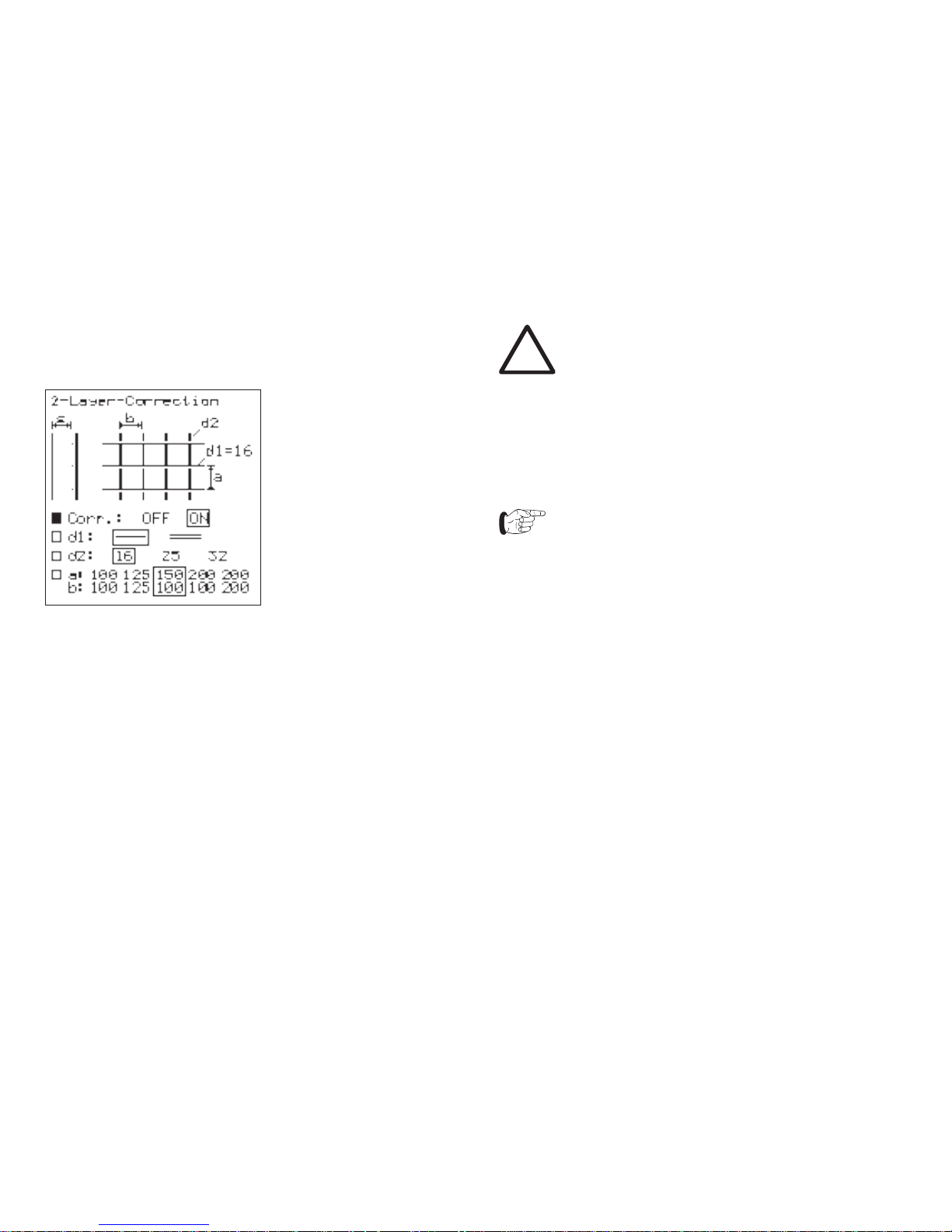
2-Layer-Correction
This mode is used for cover measurement in congested
standard orthogonal bar arrangements. A more accurate
cover reading can be reached by use of this correction.
The congested bars induce a too strong measuring
signal which can be corrected this way.
• Select the spacings a and b which you determined by
locating the bars. In some cases the bar diameters
cannot be measured by the PROFOMETER 5+ and
must be determined by removing the concrete. The
diameter setting is automatically selected as 16mm.
Page 14
8 Settings © 2007 Proceq SA
This mode can only be activated in measuring function
«Measurement with Statistics».
2-Layer-Correction
4.5 Language
The language of the display texts can be selected.
4.6 Basic Setups
The following settings are possible:
- Unit
If you choose «mm» the bar diameter setting can be
selected in mm and the results will be indicated in the
metric system. If you chose «inch» the bar diameter
setting can be made in bar size numbers and the
results are indicated in imperial units. Please refer also
to «Bar Diameter» on page 6.
Warning!
By changing the unit from mm to inch or vice
versa existing measured and stored values are
falsified. In order to avoid confusing results the
user must clear the memory after changing the
units.
The mode «2-Layer-Correction» can only be used for
metric units.
- Probe
When starting up the device for the first time,
the code no. engraved on the probe must be
entered in the submenu «Probe».
- Audible locating aid
(Short) beep tone selectable in two frequencies or
Variotone can be selected.
The remaining settings are described under the respective functions.
4.7 Data Output
For description, please see under «Data Output»,
page 20.
4.8 Measure with Statistics
For description, please see under «Measure with
Statistics», page 9.
Page 15

English
© 2007 Proceq SA Measuring Process 9
4.9 Scanning Bars
Model SCANLOG only
For description, please see under «Making Reinforcement Visible with CyberScan», page 14.
4.10 Measure with Grid
Model SCANLOG only
For description, please see under «Measure with Grid»,
page 17.
5 Measuring Process
5.1 Measure with Statistics
This function can be used to locate rebars, measure
concrete covers and determine bar diameters. The cover
values can be stored under object numbers.
5.1.1 Rebars Connected with Binding Wires
Settings
See also under «Settings», page 6.
• Enter the bar diameter.
If the bar diameter is unknown,
enter 16 mm.
• Enter the object number.
Limit value: To avoid confusions, set the limit value
to «0» during the measuring process. Enter the value
required for the building after completion of the series of
measurement. The percentage of the covers that are too
small will be displayed in the statistical evaluation. See
also «Detecting Insufficient Concrete Cover», page 12.
• Enter the desired audible locating aid («MENU» →
«Basic setups» → «Audible locating aid»): (Short) beep
tone or variotone.
• Enter the requested values under the menu option
«Corrections» → «Neighbouring Bar Correction» or «2 Layer-Correction» if the correction is required.
• Select the «Measure w. Statistics» function.
• Press the START/RESET key.
Page 16

10 Measuring Process © 2007 Proceq SA
The measuring display appears:
Preselected bar diameter
Bar spacing or limit value if set
Object number
Symbol for measuring range
Flow bar shows proximity of
probe to bar
Diameter if measured
Signal value
Intermediate storage of
concrete cover
Backlight switched on
Current cover, continously updated
Fig. 5.1 Measuring display «Statistics»
If required the backlight of the LCD can be switched on.
This can be done by pressing key ↑ for more than 2s.
RESET process
• Hold the probe in the air and press the START/RESET
key. A bar appears in the display that informs you on the
progress of the procedure. The probe shall not be moved
before the bar has disappeared and «0» is displayed.
• Please repeat this check procedure from time to time.
Locating the rebars and measuring the concrete cover
For locating the rebars, the diameter setting is not as
important as for measuring the cover.
In the case of double layer arrangements of
rebars, always start the location with the first
layer.
If the rebars of the first layer are too close to
each other, it is likely to be impossible to lo cate the bars of the second layer. See also
«Universal Probe», page 4.
• Move the probe from a starting position in one direc tion. Observe the locating aids: current concrete cover,
flow bar, (short) beep, variotone, signal value. As long
as the flow bar moves to the right, the probe is approa ching a rebar. If the flow bar stops moving, the probe is
directly over the rebar axis. If the centerline of the
probe has overshot the rebar axis somewhat, acoustic
and visual indication is given in the «beep» setting by a
short beep and by «—» in the «Current cover» display
field. At the same time, the flow bar moves to the left
and the cover is temporarily stored in the field Memo».
• When having activated the audible locating aid «Vario tone» («MENU» → «Basic Setups» → «Audible locating
aid»), the audio frequency increases as the probe
approaches a rebar. In this operation mode the cover
of the scanned rebar is also temporarily stored in the
field «Memo».
• In the case of loud noises from the surroundings, use
the headset to hear the acoustic signals.
Page 17

English
© 2007 Proceq SA Measuring Process 11
Irrespective of the settings, the signal value is
a yardstick for the distance between the probe
and a metallic object.
• The bar direction can be detected by moving the probe
in the direction of its longitudinal axis along the rebar.
Make sure that the signal value and the current cover
remain as constant as possible.
Storing the measured values
To store the measured values, select an object number
in the menu.
• Press the PRINT/STORE key to store the measured
value shown in the field «Memo».
• Use the ↓ key to delete the measured value, or in the
case of several values, the last of the remaining mea sured values.
Warning!
You cannot undo the deletion of a value!
• To receive a statistical evaluation of the stored measu red values, press the END key.
• If you then enter a limit value («MENU» → «Limit Value»),
the percentage of the measured values which are
below the entered limit value is displayed.
• Pressing END again completes the measurement
series and starts a new one with an object number that
is incremented by 1.
Measuring the diameter
See «Rebars Connected with Binding Wires», page 13.
5.1.2 Welded Reinforcing Meshes
The unit cannot detect whether the rebars are welded to
one another or connected with binding wires. The two
reinforcement types with the same dimensions however
create different signals.
Settings
• Proceed as described under «Rebars Connected with
Binding Wires», page 13.
• Observe the following exception:
The setting of the bar diameter must be slightly higher
than the actual diameter (see Tab. 5.1, page 12). The
input depends on the bar diameter and on the mesh
width. With special constructions, this value should be
determined by means of a test on an open system.
Use different distance pieces to find out the diameter
setting at which the correct cover is indicated.
Examples for diameter settings:
Fig. 5.2 Welded reinforcing mesh
Page 18

12 Measuring Process © 2007 Proceq SA
Tab. 5.1
• Select the small measuring range in the measuring
display. The large measuring range cannot be used
with welded reinforcing meshes.
Locating and measuring concrete covers
Here, the spacings between the bars of the other layers
of the mesh can also be located more easily. This particularly applies to the bars of the second layer.
The value displayed for the cover of a bar of the first
layer can vary by a few millimeters depending on whether the measurement is made over the point at which two
bars cross, or between the bars of the second layer.
If the rebars of the first layer are too close to
each other, it is likely to be impossible to loca te the bars of the second layer. See also
«Universal Probe», page 4.
Storing the measured values
• Proceed as described under «Storing the measured
values», page 11.
Measuring the diameter
«Welded Reinforcing Meshes», page 14.
5.2 Detecting Insufficient Concrete Cover
This function can be used for the following tasks:
- Check after removing formwork
- Building inspection
- Evaluation basis for modernisation
Settings
See also under «Settings», page 6
• Enter the bar diameter.
• Enter the limit value of the cover.
• Enter the bar spacing under the menu option «Neighb.
Bar Corr.» if the correction is required. The set limit va lue is not displayed in this case (see Fig. 5.1).
The setting of the audible locating aid is not of importance.
Measuring the concrete cover
With a preselected limit value, the probe can be moved
at a maximum search speed of 0.25 m/s without having
to watch the display. If the current cover displayed is less
than the limit value, an acoustic alarm sounds. When the
probe is over the bar, «—» is indicated in the «Current
concrete cover» display field.
Switching off the unit deletes the set limit
value.
Page 19

English
© 2007 Proceq SA Measuring Process 13
5.3 Determining the Bar Diameter
5.3.1 Rebars Connected with Binding Wires
A. Determining diameters without correction
For precise determination of the bar diameter, it is important that there are no unnoticed influences that could falsify the result. Therefore select a place on the structure
where there is sufficient spacing between the rebars.
If the spacings are too small, the resulting value will be
too high.
To measure the bar diameter in the first and second
layer, the minimum spacings a and b as shown in Tab.
5.2, page 13 are required.
• Select the «Measure w. Statistics» function.
• Carry out the RESET procedure. See also under
«RESET process», page 10.
• Place the probe parallel over the bar and press the ↑ key.
• The result of the bar diameter determination is
displayed in mm or inch.
Fig. 5.3 Rebar of 1st Fig. 5.4 Rebar of 2nd
layer layer
Tab. 5.2 Minimum spacings of the rebars in the 1st and 2nd
layer
Provided that the minimum spacings are observed, the
rebars can be measured with an accuracy shown in
Fig. 5.5.
mm
mm
Fig. 5.5 Determining diameters
Page 20

14 Measuring Process © 2007 Proceq SA
The result of diameter determination cannot be
stored.
B. Determining diameters with correction
There are structures where the rebar spacing is smaller
than indicated in Tab. 5.2. Corrections are possible for
these structures. However, this only applies to the parallel bars on both sides. The bars that run crosswise must
have the minimum spacings shown in Tab. 5.2.
Procedure:
• Locate the parallel rebars carefully and mark them on
the surface of the concrete.
• Measure the rebar spacings using a measuring rod
and enter the data in the «Corrections» → «Neighb.
Bar Corr.»
• Select the «Measure w. Statistics» function.
• Hold the probe in the air and carry out the «RESET
process» as described on page 10.
• Place the probe parallel over a bar and press the ↑ key.
As bar diameter (d=...), the display shows the value corrected by the influence of the neighboring bars.
• In addition to the bar spacing, the measured bar dia meter can now be entered in the menu.
With these settings, the concrete cover of those rebars
found to be situated close to one another can be determined precisely.
Only concrete covers can be stored under the
selected object number, not the measured bar
diameter!
5.3.2 Welded Reinforcing Meshes
If diameters are determined on welded rebar systems,
results are displayed most of the time. These values are,
however, always too high and cannot be used.
5.4 Making Reinforcement Visible with
CyberScan
Model SCANLOG only (with mobile probe)
The rebars arranged below a defined measuring area
are displayed. Using the x/y scales, rebars which have
to be exposed, or points where holes have to be drilled,
can be transferred immediately from the display to the
measuring area and marked.
The measuring area must be scanned with the mobile
probe once in direction x and once in direction y (see
«ScanCar», page 5). The rebars are located and displayed extended to the full size of the measuring area.
Measuring areas of 0.5 x 0.5 m, 1 x 1 m or 2 x 2 m can
be selected.
If the area that must be measured is smaller than the
size of the selected area the bars are only shown in the
length they were measured.
Page 21

English
© 2007 Proceq SA Measuring Process 15
x meter scale
Cursor
1st layer
2nd layer
Direction of travel of the
probe
Concrete covers of the 1st and 2nd layer
Preselected bar diameter
y meter scale
Fig. 5.6 Example of a measured object
Settings
See also «Settings», page 6.
• Enter the bar diameter of the first layer.
• Enter the object number.
• Enter the bar spacing under the menu option «Neighb.
Bar Corr.» if the correction is required. The «2-Layer correction» cannot be used by this function.
• Enter the size of the measuring area («MENU» →
«Basic setups» → «Scan Area»).
• Select the measuring function «Scanning Bars».
• Press the START key.
The following measuring display appears:
Fig. 5.7 Measuring display «CyberScan»
• Locate a rebar of the first layer in the measuring area
and mark it precisely. Then mark the left or top limit of
the measuring area parallel to the previously marked
bar on the concrete element.
Direction of travel:
The front of the mobile probe is where the
single wheel is.
Page 22

• Use the ↑, ↓, ←, →
keys to end the mea-
suring process of the
1st layer:
Fig. 5.10 Instructions
4 Smallest measured
cover of the 1st layer
• Place the cursor bet ween 2 rebars that are
as far apart as possible.
• Mark the position on
the measuring area.
• Start measuring the
bars in the 2nd layer
from this position.
• After the measuring
area has been scan ned, the following
display appears:
Fig. 5.11 Rebars of 2nd
layer
• Use the ↑, ↓, ←, →
keys to end the mea suring process of the
2nd layer. The smallest
concrete cover is indi cated.
• Press the PRINT/
STORE key to store
the measuring display.
• Press the END key if
the result must be
deleted.
16 Measuring Process © 2007 Proceq SA
Measuring procedure
• Start with the END key.
The following display
appears:
Fig. 5.8 Scanning
display
• Determine the direction
of travel using the ↓,
→ keys.
• Position the travel path
where the concrete ele ment is to be examined.
• Please note that loca ting and measuring is
in relation to the center
of the probe.
• After the measuring
area has been scan ned, the following is
displayed:
Fig. 5.9 Rebars of 1st
layer
• Travelling backwards
with the probe deletes
the displayed rebars.
1 Speed display. The
flow bar must be within
the scale.
2 Current concrete cover
3 Symbol for travelling
and scanning
The layer measured first
is displayed in thicker
lines.
1 2 3 4
Page 23

English
© 2007 Proceq SA Measuring Process 17
5.5 Measure with Grid
Model SCANLOG only
This function displays concrete covers over a large area
in grey scale or colour shades. The smallest concrete
cover measured in a grid field is displayed.
Settings
See also «Settings», page 6.
• Enter the bar diameter of the first layer.
• Enter the object number.
• Enter the bar spacing under the menu option
«Corrections»
→ «Neighb. Bar Corr.» if the correction is required.
The «2-Layer Correction» can not be used by this
function.
• Select the size of the grid field («MENU» → «Basic
setups» → «xy-grid»).
The grid should usually be greater than the division of
the first layer (e.g. +50 %) to ensure that at least one
rebar is within a grid field.
• Set the range in which the concrete covers are to be
displayed in grey scale («MENU» → «Basic setups»
→ «Display»).
Change the grey scale range to improve the contrast of
the displayed object (see Fig. 5.12).
Fig. 5.12 Adjusting grey scale range
The range can be adjusted as desired even after
measuring.
• Select the «Measure with Grid» function.
• Pressing the START key calls the measuring display:
Fig. 5.13 «Measure with Grid» measuring display
Page 24

5.5.1 Measuring with the Mobile Probe
• Scan the area to be measured with the mobile probe
(see «ScanCar», page 5) while observing the selected
grid.
Upper limit of object
Marking the travel paths acc.
to x/y-grid
Rebar of 1st layer
Left limit of object
Fig. 5.14 Measuring with the mobile probe
Direction of travel:
The front of the mobile probe is where the
single wheel is.
The front must always be opposite the x or y
axis. The direction of travel can be forward or
backward.
• Pressing the END key calls the top left corner of the
measuring area:
The x/y-coordinates are indicated in meters or feet.
One page contains 16 x 15
measured values that are
displayed in grey scale and
stored. The memory has a storage capacity of 500 pages.
The number of the remaining
free pages is indicated in the
measuring display (see Fig.
5.13).
5 4 3 2
1
Fig. 5.15 Measuring area before measuring
Key:
1 Cursor:
Press the ↑, ↓, ←, → keys briefly to move the cursor
step by step.
Keep the ↑, ↓, ←, → keys permanently pressed to go
to the next pages.
2 The arrow indicates the measuring direction. With the
↑, ↓, ←, → keys the measuring direction can be
changed.
3 Current concrete cover
4 Grey scale symbol of the current concrete cover
5 From 10 m in direction x, 10 a.s.o. is displayed.
• Follow the instructions in the display of Fig. 5.15 before
starting measuring.
18 Measuring Process © 2007 Proceq SA
Page 25

English
© 2007 Proceq SA Measuring Process 19
Scanning the measuring area with display of the
concrete covers
Key:
6 Speed display. The flow
bar must be within the
scale.
7 Smallest measured
concrete cover
8 Current concrete cover
9 Symbol for travelling and
scanning
6 7 8 9
Fig. 5.16 Measuring area after measuring
• If the rebars of the first layer run in a vertical direction
as shown in Fig. 5.14, the travel paths must
be positioned horizontally with the selected grid spa cing in direction y. Move the mobile probe along these
paths. In Fig. 5.16, pos. 7, the smallest concrete cover
measured in a grid field is displayed and stored auto matically as grey scale.
• After having finished one row, press the ↓ key. The
cursor jumps to below the last field and the arrow
direction changes automatically.
After every manual or automatic change of the
arrow direction, RESET must be pressed. See
also «RESET process», page 10.
• Once the second row at the edge of the measuring
area (y-axis) is completed, the cursor jumps to below
the last field and the arrow direction changes automa tically.
The indicating device operates in the same way if the
travel paths are positioned vertically, i.e. if measuring is
performed in direction y.
• If a hindrance prevents the measurements, you can
shift the cursor by the size of the obstacle.
• Individual values can be deleted by positioning the
cursor on the respective value and pressing the
PRINT/STORE key for two seconds.
• You can subsequently expand the object opened last in
the x and y-direction on new pages comprising 240
measured values.
• For all previous objects, measured values can only be
entered in pages that are not yet full.
• If the measurement cannot be started in the top left
corner (x and y = 0) you can move the cursor to the
starting position using the corresponding arrow keys.
• If you want to reserve pages that will be needed later,
each page has to be selected separately. To confirm
the reservation you can set a grey scale symbol in the
second row using the PRINT/STORE key. The grey
scale symbol can be overwritten or deleted at any time.
Page 26

5.5.2 Measuring with the Universal Probe
Measuring with grid can also be performed with the
probe only, i.e. without path measuring (ScanCar). To do
this, the x/y-grid has to be drawn on the concrete surface
to be measured.
• Carry out the same settings as for «Measuring with the
Mobile Probe», page 18.
• During measuring, the grid fields must be scanned with
the universal probe.
• Please note that the smallest concrete cover measured
in a grid field is always displayed (see Fig. 5.16,
Pos. 7). Store this value using the PRINT/STORE key.
5.6 Data Output
Characteristics of the menu items:
5.6.1 Object Select
All object numbers used are listed.
5.6.2 Object Display
An object which has been selected from the list is called
from the memory and displayed.
5.6.3 Object Print
The object can be printed with the printers listed below.
They can be connected directly to the indicating device.
• Hewlett Packard Deskjet printers for graphic and
numerical printout.
• EPSON printers for numerical printout.
Printers with a parallel interface require the serial/parallel
interface converter, Art. No. 390 00 188. For printers with
a serial interface, use the printer cable Art. No. 330 00 460.
• Select the corresponding function in the «Printer select»
submenu.
Below, you will find examples of printouts of various
objects.
Fig. 5.17 Printout of a «Measure w. Statistics» object
20 Measuring Process © 2007 Proceq SA
Page 27

English
© 2007 Proceq SA Measuring Process 21
Fig. 5.18 Printout of a Fig. 5.19 Printout of
CyberScan object «Measure with
Grid» object
5.6.4 Object to PC
Data can be transferred to PC and edited by use of
the programme ProVista supplied on a data carrier.
Instructions on the installation of the software and the
operation can be found on the data carrier. For data
transfer to the RS232 interface use the transfer cable,
Art. No. 330 00 456. If only a USB interface is available an additional RS232/USB adapter, Art. No. 390 00
540 must be used. Information on the installation of the
adapter can be found on the included CD.
Fig. 5.20 Fig. 5.21
Object «Measuring with statistics» «Cyberscan» object
Fig. 5.22 Object «Measuring with grid»
5.6.5 Clear memory
Objects cannot be deleted individually
You can only delete the entire memory con-
tents. This action cannot be undone after it
has been confirmed.
Page 28

22 Maintenance and Storage © 2007 Proceq SA
6 Maintenance and Storage
6.1 Cleaning
Warning!
Never immerse the indicating device or
measuring equipment in water or wash it under
a running tap! Use neither abrasives nor
solvents for cleaning!
• Clean the indicating device and measuring equipment
with a clean, dry cloth after use.
• Clean dirty input sockets and connectors with a clean,
dry brush.
6.2 Performance Check
• Check the cables for damage.
• All measuring functions can be checked with the test
block, Art. no. 390 00 270.
• If the battery life symbol is only ¼ black a set of new
batteries should be taken on site.
6.3 Storage
• Store the indicating device and measuring equipment
in the original case and in a clean, dust-free room.
• If the unit is not used for a long period of time, remove
the batteries.
Page 29

English
© 2007 Proceq SA Data 23
7 Data
7.1 Form of Delivery
Model S Model
SCANLOG
Article no. 390 00 050 390 00 054
Indicating device
Carrying strap
Universal probe incl. protec-
tive film
Probe cable 1.5 m
ScanCar probe carriage with Option
path measuring cable 1.55 m
Interface converter serial/ Option
parallel incl. 2.0 m cable
Transfer cable 1.5 m
USB-memory stick for data
transfer
Headset
Protection sleeve for display
unit
Operating instructions
Carrying case
415 x 500 x 125 mm
Total weight 4.2 kg 4.5 kg
Model S
Model SCANLOG
Page 30

24 Data © 2007 Proceq SA
7.2 Accessories / Spare Parts
Designation Article no.
Extension rod for universal probe and 390 00 076
ScanCar
Test block 390 00 270
Marking pen 390 00 280
Protective film for universal probe 390 00 084
Headset 390 00 085
Protection sleeve for indicating device 330 00 470
Transfer cable 9/9-poles 330 00 456
Printer cable 9/9+25-poles for printer with 330 00 460
serial interface
Interface converter serial/parallel for printer 390 00 188
with parallel interface
RS232/USB adapter 390 00 540
Upgrading from model S to model SCANLOG 390 00 090
7.3 Technical Data
7.3.1 Indicating Device Model S
- Non-volatile data memory for 40 000 measured values,
can be divided into 60 objects
-
Graphics LCD, 128x128 pixels with backlight
- Interface RS 232
- Software for direct printing. ProVista software for data
transfer to PC and editing
- Power supply with 6 batteries, 1,5V, LR6 for an
operating time of approx. 45h, or 30h with switched on
backlight. We suggest to use alkaline batteries
- Permissible ambient temperature for the whole device:
-10 °C to +60 °C
7.3.2 Indicating Device Model SCANLOG
Model SCANLOG is identical to model S but additionally
includes:
- «CyberScan» function for displaying the concrete cover
on the indicating device
- «Measure with Grid» function for grey scale display of
the concrete cover
- Extended data memory:
- Storage areas for «CyberScan»
- Storage areas for «Measure with Grid»:
500 pages with 16 x 15 = 240 measured values
each
- The maximum number of objects, however, remains
60; #200 000 and 300 000 are demo objects
 Loading...