

Page 1

... more than 50 years of know-how you can measure!
Made in Switzerland
Operating Instructions
Moisture Meter
Page 2

2© by Proceq SA
Contents
1. Safety and Liability 3
1.1 Safety and usage precautions 3
1.2 Liability and warranty 3
1.3 Safety instructions 3
1.4 Correct Usage 3
2. Tutorial 4
3. Getting started 4
3.1 Insert Battery 4
3.2 Contact In-Situ and/or Ambient Probe 4
3.3 Overview Keypad 5
3.4 Standard Display 5
3.5 Overview Screens & Menu Structure 6
3.6 Detailed Menu Structure & Settings 7
4. HygroLink 10
5. Step by Step Guide “Relative Humidity Testing according to ASTM F2170” 11
6. Example of Test Report 12
7. Technical Specifications 13
8. Part Numbers and accessories 14
8.1 Units 14
8.2 Parts and Accessories 14
9. Maintenance and Support 14
9.1 Support Concept 14
9.2 Standard Warranty and Extended Warranty 14
Page 3

3© by Proceq SA
1. Safety and Liability
1.1 Safety and usage precautions
This manual contains important information on the safety, use and maintenance of the Hygropin.
Read through the manual carefully before the first use of the instrument. Keep the manual in a safe
place for future reference.
1.2 Liability and warranty
Proceq’s “General Terms and Conditions of Sale and Delivery” apply in all cases. Warranty and liability claims arising from personal injury and damage to property cannot be upheld if they are due
to one or more of the following causes:
Failure to use the instrument in accordance with its designated use as described in this •
manual.
Incorrect performance check for operation and maintenance of the instrument and its •
components.
Failure to adhere to the sections of the manual dealing with the performance check, •
operation and maintenance of the instrument and its components.
Unauthorized structural modifications to the instrument and its components.•
Serious damage resulting from the effects of foreign bodies, accidents, vandalism and •
force majeure.
All information contained in this documentation is presented in good faith and believed to be
correct. Proceq SA makes no warranties and excludes all liability as to the completeness and/or
accuracy of the information.
1.3 Safety instructions
The instrument is not allowed to be operated by children or anyone under the influence of alcohol,
drugs or pharmaceutical preparations. Anyone who is not familiar with this manual must be
supervised when using the instrument.
1.4 Correct Usage
The instrument is only to be used for its designated purpose as describe herein.•
Replace faulty components only with original replacement parts from Proceq.•
Accessories should only be installed or connected to the instrument if they are expressly •
authorized by Proceq. If other accessories are installed or connected to the instrument then
Proceq will accept no liability and the product guarantee is forfeit.
Page 4

4© by Proceq SA
2. Tutorial
The Hygropin is a multifunction hand-held indicator with data logging capability that can be used
for identifying, diagnosing and monitoring potential moisture problems. Each of the two probe
inputs can be configured independently. The integrated real time clock keeps track of date and
time while recording data.
Practical advice for measuring humidity
The most common source of error when measuring relative humidity is a difference between the
temperature of the probe and the temperature of the environment. At a humidity condition of 50
% RH, a temperature difference of 1°C (1.8 °F) typically results in an error of 3 %RH on relative
humidity.
When using Hygropin, it is good practice to monitor the display for temperature stability. The probe
should be given sufficient time to come to equilibrium with the environment to be measured. The
larger the initial temperature difference between the probe and the environment, the more time is
required for temperature equilibrium.
In extreme situations, condensation may occur on the sensors when the probe is colder than the
environment. As long as the humidity / temperature limits of the humidity sensor are not exceeded,
condensation does not alter the calibration of the sensor. However, the sensor has to dry out before it can provide a valid measurement.
3. Getting started
3.1 Insert Battery
3.2 Contact In-Situ and/or Ambient Probe
Page 5

5© by Proceq SA
3.3 Overview Keypad
ON / OFF Turns the instrument “on” or “off”.
MENU Activates the internal menu. Press this key again to go back.
UP Change data displayed, navigate through menu, make a
DOWN selection or change values.
ENTER Confirm a selection and data capture.
3.4 Standard Display
Depending on the settings the Hygropin is able to display:
relative humidity and temperature measured by two probes•
calculate psychrometric parameters like dew / frost point etc. for both probes•
difference between the values measured by the two probes•
Press slightly button to turn the Hygropin on:
Trend Indicator
increasing value
decreasing value
stable value
Humidity and
Temperature
Data Logging
Logging for Probe 1
is active.
Probe selected
Date and Time
Battery charge indicator
Change probe that is displayed or scroll through the measuring values using the or
button.
By pressing the temperature and humidity values of the selected probe are stored. More
information can be found in the Data Capture chapter.
Enter the Menus and Settings screens by pressing the key:
Page 6

6© by Proceq SA
3.5 Overview Screens & Menu Structure
Standard
H+T+Calc
Large
Page 7

7© by Proceq SA
3.6 Detailed Menu Structure & Settings
Device Info
Serial Number
Software Version
Device Type
Device Name
Battery Charge Status
Device Settings
Submenu Display Settings
Submenu Local Settings
Submenu Input 1 / Input 2 Settings
Barometric pressure for calculations
see “Calculated Parameters”
Display refresh interval 1 s / 10 s / 1 min / 10 min
Battery charge via USB ON / OFF
Manual date setting
Manual time setting
Submenu Display Settings
Trend indicator on display ON / OFF
Decimal display resolution 0.x / 0.xx
Display contrast adjustment 0..50
Back light mode ON / OFF / Key pressed
Display Mode Standard / H+T+Calc / Large
Show difference for each parameter between Probe 1 and
Probe 2
ON / OFF
Submenu Local Settings
Date format dd mm yyyy
mm dd yyyy
yyyy mm dd
Date separator “.” or ”/”
Time format 24 h / 12 h
Unit system Metric / English
Real time clock does not auto adjust for daylight saving time.
Page 8

8© by Proceq SA
Submenu Probe Settings
Probe Type HygroClip / Analog / Pressure
Calculation (digital probe
only)
See “Calculated Parameters”
Output Voltage (analog probe)
…
Measuring Range (analog
probe)
…
Calculated Parameters
The Hygropin can calculate any of the following psychrometric parameters based on humidity and
temperature:
Dew point (Dp) above and below freezing•
Frost point (Fp) below freezing and dew point above freezing•
Wet bulb temperature (Tw)•
Enthalpy (H)•
Vapor concentration (Dv)•
Specific humidity (Q)•
Mixing ratio by weight (R)•
Vapor concentration at saturation (Dvs)•
Vapor partial pressure (E)•
Vapor saturation pressure (Ew)•
Any of the above parameters can be set in the submenu “Probe Setting”.
Calculating some of these parameters requires barometric pressure as an input parameter. A fix
barometric pressure value can be specified in the “Device Settings” Menu.
Probe Menu
Submenu detail information digital probe
Submenu Humidity Adjustment
Submenu Temperature Adjustment
These functions are for service and calibration purpose only.
Page 9
9© by Proceq SA
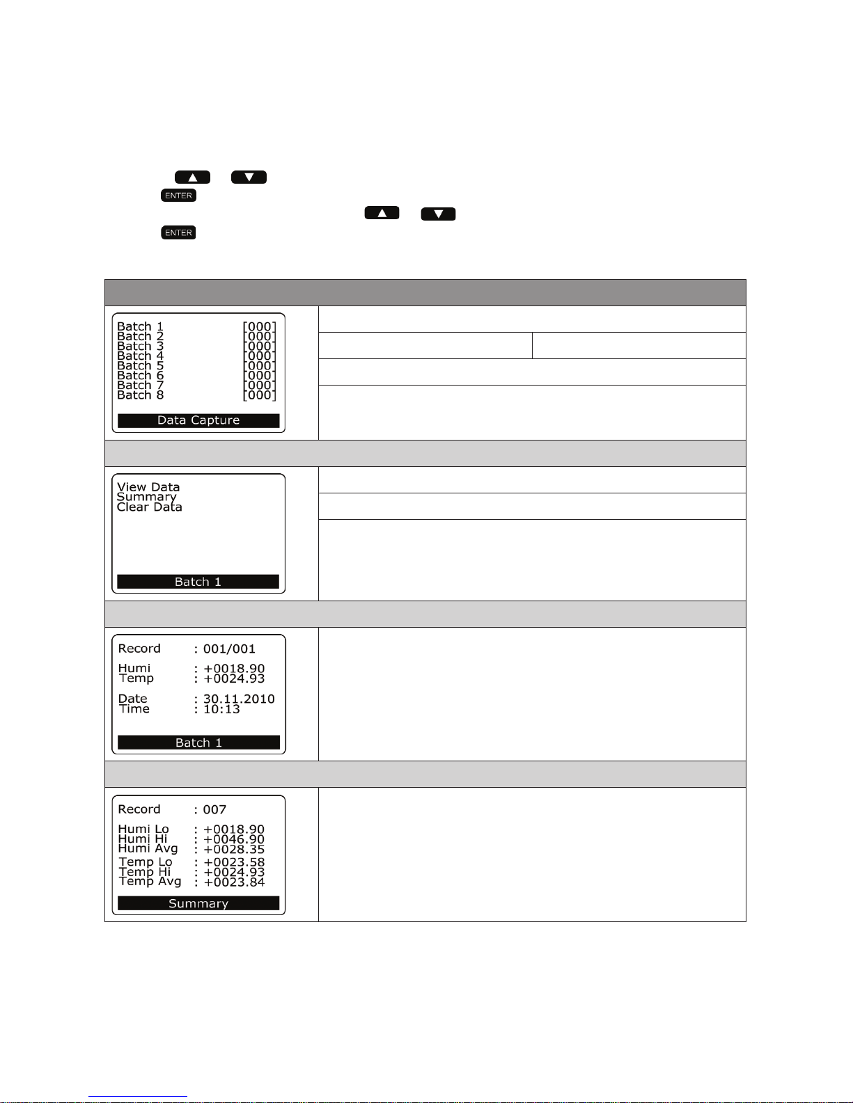
Data Capture
Up to 250 relative humidity and temperature records can be manually captured and organized in
each of the 8 data batches (non-volatile memory). The captured data is automatically date and time
stamped. The calculated parameter cannot be captured.
Capturing Data:
Use the • or key to select the probe
Press •
Select the target data batch with the • or key
Press • to trigger the Data Capture function
Data capture is confirmed on the Hygropin display•
Data Capture
Data Batch 1 [Numbers of Records]
…
Data Batch 8 [Numbers of Records]
Select data batch to be viewed
Submenu Batch 1..8
Submenu View Data
Submenu View Summary Batch
Clear Data Batch
Submenu View Data
View individual data records inclusive date and time stamp.
Submenu Summary
View the maximum, minimum and average values of each
batch.
Page 10

10© by Proceq SA
Data Logging
The Hygropin can automatically record up to 10,000 humidity-temperature values measured by a
single probe. Each record is stamped for date and time. The calculated parameter cannot be recorded. When recording data from two probes at the same time, the recording capacity per probe
is cut in half.
The Hygropin features two data logging mode: start-stop (recording ends when the memory is full)
and loop (when the memory is full, the oldest record is dumped to make room for a new record)
Data logging can be started and stopped from the keypad. The HygroLink software allows the
downloading of the recorded data for further analysis.
Data Logging
Status Data logging ON / OFF
No. of sample taken max. 10’000 H+T
Status Logging Interval 5s…1h
Status Logging Mode StartStop / Loop
Start / Stop Recording
Submenu Settings
Submenu Settings
Interval setting 5s..1h
Logging Mode setting StartStop / Loop
Logging Probe 1 ON / OFF
Logging Probe 2 ON / OFF
Cannot be changed while the Hygropin is recording data.
4. HygroLink
Installation
To start the installation wizzard of the software & driver package execute HygroLink_Setup.exe on
the included CD ROM.
Remove the red cover cap and connect the USB cable to the connector.
1. Establish connection to Hygropin
2. Download all data from the Hygropin in Excel-Files
3. Delete all data on the Hygropin
4. Disconnect Hygropin
5. Check for updates HygroLink
Page 11

11
© by Proceq SA
5. Step by Step Guide
“Relative Humidity Testing according to ASTM F2170”
For details please check the ASTM F2170-09 standard.
Step 1: Check the correct functionality of the instrument (Chapter 8, ASTM F2170-9)
Recalibrate probes annually•
Check periodically the correct functionality of instrument and probe with the humidity •
standard tube (780 10 470)
Step 2: Conditioning (Chapter 9, ASTM F2170-9)
Concrete floor slab and air space surrounding slab shall be at service temperature /
humidity for at least 48 hours.
Step 3: Define number of test holes (Chapter 10.1, ASTM F2170-9)
3 test holes for the first 1000 ft•
2
/ 100 m2
at least 1 additional test hole for each additional 1000 ft•
2
/ 100 m
2
Step 4: Define depth of test holes (Chapter 10.2, ASTM F2170-9)
40% of slab thickness if slab is drying from top only•
20% of slab thickness if slab is drying from top and bottom•
Step 5: Drill and prepare test holes (Chapter 10.3, ASTM F2170-9)
Drill hole using a 8mm /
5/16in drill bit
Clean test hole
Cut sleeve according to
measuring depth
Insert sleeve in test hole
and close cap
Cast holes (Chapter 10.4, ASTM F2170-9)
Use “Add-on for wet
concrete” (780 10 370)
Cut sleeve and rod
according to measuring
depth
Remove rod after concrete hardens
Close cap
Step 6: Wait 72 hours for moisture equilibrium (Chapter 10.3.4, ASTM F2170-9)
Step 7: Measurements (Chapter 10.5, ASTM F2170-9)
Insert In-Situ probe into
sleeve
Wait for temperature
equilibrium
Check for stable value
(trend indicator) before
record data
Measure ambient
condition
Step 8: Report (Chapter 11, ASTM F2170-9)
Use the Test Report template (chapter 6) to record and report all necessary information.
Page 12

12© by Proceq SA
6. Example of Test Report
Name and address of structure: Identify floor:
Area: .................... m2 ft
2
No. Holes ....................
Slab thickness: .................... mm inch
Test Location
(use room number or building
grid)
Depth from top of
slab
mm inch
Relative Humidity in concrete, %
Temperature in
concrete,
°C °F
Ambient
Temperature,
°C °F
Ambient
Relative Humidity %
Notes:
Instrument used: Make, Model, Serial number Instrument used: Last calibration date of probe
Test performed: Name Test performed: Date
Test performed: Company name Test performed: Company address
Location Map
Instructions: Indicate sensor locations with symbol and number of test hole. Show doors, rooms,
columns or other location indicators.
Page 13

13© by Proceq SA
7. Technical Specifications
Display Unit
Power Supply
Battery 9 V alkaline (standard)
Ni-MH 8.4V, 170…250mAh (rechargeable via USB)
Mains Via USB charger
General
Probe input Two separate digital probe inputs
Real time Clock Yes
Psychrometric Calculations Yes
Start-up time 3 s
Data refresh rate 1 s
Interface type USB
Data Logging
Memory Max. 10’000 readings
Interval 5 s to 1 h
Display
Display Pixel graphic LCD
Backlight
Display modes % RH and temperature, date and time
% RH, temperature and calculated parameter
Mechanical
Dimension 270 x 70 x 30 mm (10.63 x 2.76 x 1.17”)
Weight Ca. 198 g (7.0 oz)
IP classification IP 40
Environmental conditions
Operating temperature -10 °C to 60 °C (14 °F to 140 °F)
Humidity 0 to 100% RH, no condensing
In-Situ Probe
Measuring range 0 to 100% RH
- 40 °C to 85 °C (-40 °F to 185 °F)
Accuracy ± 1.5 % RH / ± 0.3 K
Response time < 15 s
Dimension Ø 5 mm (Ø 0.2 in.)
Cable length 200 cm (79 in.)
Maximum air velocity at probe 20 m/s (3,935 ft /min)
Page 14

14© by Proceq SA
Standards and Regulations applied
CE / EMC immunity
EMC Directive 2004/108/EG:•
EN 61000-6-1: 2001•
EN 61000-6-2: 2005•
EN 61000-6-3: 2005 •
EN 61000-6-4: 2001 + A11•
Technical Standard
ASTM F 2170-09•
Special note NIST traceability:
All probes for the Hygropin are factory calibrated referring to the Swiss Calibration Service (SCS).
An individual calibration certificate is included with each probe. SCS is accredited with the Swiss
Federal Office of Metrology which is a signatory of the BIPM (http://www.bipm.org/) Under the
Mutual Recognition Agreement NIST recognizes all registered in the BIPM database.
8. Part Numbers and accessories
8.1 Units
Part No. Description
780 10 000 Hygropin Unit consisting of: Instrument incl. In-situ probe, carrying case and ac-
cessories (10pcs measuring sleeves, CD incl. HygroLink, documentation)
8.2 Parts and Accessories
780 10 400 In-Situ Probe
780 10 450 Ambient Probe
780 10 470 Humidity Standard 75%RH
780 10 350 Set of Measuring Sleeves 20pcs
780 10 360 Set of Measuring Sleeves 100pcs
780 10 370 Add-on for Wet Concrete 10pcs
9. Maintenance and Support
9.1 Support Concept
Proceq is committed to providing a complete support service for this instrument. It is recommended that the user registers the product on the www.proceq.com to obtain valuable information
on available updates and other useful information.
9.2 Standard Warranty and Extended Warranty
The standard warranty covers the electronic portion of the instrument for 24 month and the mechanical portion of the instrument for 6 month. An extended warranty for one, two or three years for
the electronic portion of the instrument may be purchased up to 90 days of purchase.
Page 15

15© by Proceq SA
Page 16

... more than 50 years of know-how you can measure!
Made in Switzerland
Proceq Europe
Ringstrasse 2
CH-8603 Schwerzenbach
Phone +41-43-355 38 00
Fax +41-43-355 38 12
info-europe@proceq.com
Proceq UK Ltd.
Bedford i-lab, Priory Business Park
Stannard Way
Bedford MK44 3RZ
United Kingdom
Phone +44-12-3483-4515
info-uk@proceq.com
Proceq USA, Inc.
117 Corporation Drive
Aliquippa, PA 15001
Phone +1-724-512-0330
Fax +1-724-512-0331
info-usa@proceq.com
Proceq Asia Pte Ltd
12 New Industrial Road
#02-02A Morningstar Centre
Singapore 536202
Phone +65-6382-3966
Fax +65-6382-3307
info-asia@proceq.com
Proceq Rus LLC
Ul.Optikov 4
korp.2, lit. A, Office 321
197374 St. Petersburg
Russia
Phone/Fax + 7 812 448 35 00
info-russia@proceq.com
Proceq Middle East
P.O. Box: 262419
Jebel Ali Free Zone
Dubai, United Arab Emirates
Phone +971 50 482 9510
info-middleeast@proceq.com
Proceq SAO Ltd.
South American Operations
Rua Haddock Lobo, 746 - 5 andar
Cerqueira Cesar, São Paulo
Brasil Cep. 01414-000
Phone +55 11 3083 38 89
info-southamerica@proceq.com
Proceq China
UnitG,10thFloor,Huamin•EmpirePlaza
No. 728, Yan An Road(W)
Shanghai, 200050
Phone +86 21-63177479
Fax +86 21 63175015
info-china@proceq.com
www.proceq.com
Subject to change without notice.
Copyright © 2010 by Proceq SA, Schwerzenbach
Part number: 820 780 01 E
 Loading...