

Page 1
Operating Instructions
60 Years of Innovation60 Years of Innovation
Swiss Precision since 1954
Page 2

Table of Contents
1. Safety and Liability ....................................................4
1.1 General Information ............................................................. 4
1.2 Liability .................................................................................. 4
1.3 Safety Instructions ............................................................... 4
1.4 Correct Usage ...................................................................... 4
1.5 Optimizing Performance of the Battery System ............... 4
2. Getting Started ...........................................................5
2.1 Installation ............................................................................ 5
2.2 Main Menu ............................................................................ 6
3. Measurement .............................................................7
3.1 Performing Measurements ................................................. 7
3.2 Measurements Screen ...................................................... 10
3.3 Measuring Methods .......................................................... 12
3.4 Instrument Verification / Daily Performance Check ....... 24
4. Settings ....................................................................25
4.1 Measurements ................................................................... 25
4.2 Verification (Performance & Uncertainty Check) ............ 27
4.3 Conversions (Hardness Conversions) ............................. 28
4.4 Reporting ............................................................................ 28
5. Data (Explorer) .........................................................29
5.1 Measurements ................................................................... 29
5.2 Verifications ........................................................................ 31
6. Wizards .....................................................................31
6.1 Measurement Wizard ........................................................ 32
6.2 Device Verification ............................................................. 32
6.3 Impact Direction Calibration (Leeb only) ......................... 32
6.4 Conversion Curve Creation............................................... 32
6.5 Combined Method ............................................................. 34
6.6 Mapping Wizard (Coming Soon) ...................................... 34
7. Information ...............................................................35
7.1 Documents ......................................................................... 35
7.2 Upload PDF-Files from an USB-stick .............................. 35
8. System ......................................................................36
8.1 Features .............................................................................. 36
8.2 Probes................................................................................. 37
8.3 Hardware ............................................................................ 37
8.4 Date & Time ........................................................................ 37
8.5 Language ............................................................................ 37
8.6 Device information ............................................................. 37
9. Maintenance and Support .......................................38
9.1 Maintenance....................................................................... 38
9.2 Support Concept ............................................................... 39
9.3 Standard Warranty and Extended Warranty ................... 39
9.4 Disposal .............................................................................. 39
© 2016 Proceq SA 2
Page 3

10. Troubleshooting ......................................................... 40
10.1 Incorrect Measurements / Failed Performance Check ..... 40
10.2 No Reading Displayed ......................................................... 41
10.3 Battery ................................................................................... 42
10.4 Touchscreen Calibration ...................................................... 42
11. Equotip Link Software ............................................... 42
11.1 Starting Equotip Link ............................................................ 42
11.2 Application Settings ............................................................ 42
11.3 Connecting to an Equotip 550 Touchscreen Unit .............. 43
11.4 Connection to Portable Rockwell Probe ............................ 43
11.5 Adjusting the Settings .......................................................... 43
11.6 Exporting Data ...................................................................... 44
11.7 Exporting and Importing of Setting Profiles ....................... 45
11.8 Exporting and Importing of Conversion Curves ................ 45
12. Technical Specifications ............................................ 45
12.1 Instrument ............................................................................. 45
12.2 Power Supply ........................................................................ 46
12.3 Equotip Leeb Impact Devices ............................................. 46
12.4 Equotip Portable Rockwell Probe ....................................... 47
12.5 Equotip UCI Probe ................................................................ 47
13. Standards & Guidelines ............................................. 47
14. Ordering Information ...............................................48
14.1 Units .................................................................................... 48
14.2 Impact Devices & Probes ................................................. 48
14.3 Parts and Accessories ...................................................... 49
14.4 Test Blocks ..............................................................................
© 2016 Proceq SA 3
Page 4

1. Safety and Liability
Table of Contents
1.1 General Information
This manual contains important information on the safety, use and maintenance of the Equotip 550. Read through the manual carefully before the
first use of the instrument.
1.2 Liability
Our “General Terms and Conditions of Sales and Delivery” apply in all
cases. Warranty and liability claims arising from personal injury and damage to property cannot be upheld if they are due to one or more of the
following causes:
• Failure to use the instrument in accordance with its designated use as
described in this manual.
• Incorrect performance check for operation and maintenance of the instrument and its components.
• Failure to adhere to the sections of the manual dealing with the performance check, operation and maintenance of the instrument and its
components.
• Unauthorised modifications to the instrument and its components.
• Serious damage resulting from the effects of foreign bodies, accidents,
vandalism and force majeure.
All information contained in this documentation is presented in good faith
and believed to be correct. Proceq SA makes no warranties and excludes
all liability as to the completeness and/or accuracy of the information.
1.3 Safety Instructions
The equipment is not allowed to be operated by children or anyone under
the influence of alcohol, drugs or pharmaceutical preparations. Anyone
who is not familiar with this manual must be supervised when using the
equipment.
• Carry out the stipulated maintenance properly and at the correct time.
• Following completion of the maintenance tasks, perform a functional
check.
1.4 Correct Usage
The instrument is only to be used for its designated purpose as described
herein.
• Replace faulty components only with original replacement parts from
Proceq.
• Accessories should only be installed or connected to the instrument
if they are expressly authorized by Proceq. If other accessories are
installed or connected to the instrument then Proceq will accept no
liability and the product guarantee is forfeited.
1.5 Optimizing Performance of the Battery System
To increase the performance of the battery, it is recommended to first
completely discharge and then completely charge it.
4 © 2016 Proceq SA
Page 5
2. Getting Started
Table of Contents
The Equotip 550 is typically used for testing the hardness of metallic surfaces. The user has a choice to select either Leeb rebound, the Portable
Rockwell or UCI principle, see chapter “3.1 Performing Measurements”.
In combination with the Equotip Leeb Impact Device U the instrument is
used to test the roll hardness of paper, film or foil rolls.
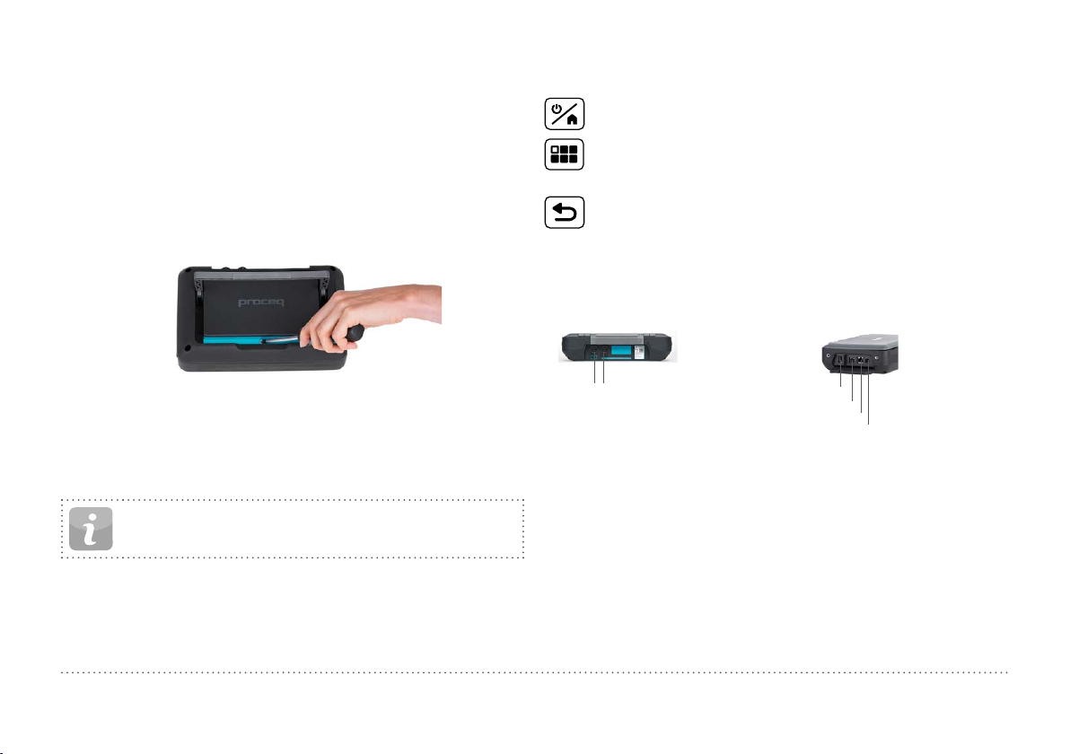
2.1 Installation
To install the Battery into the Equotip 550 Touchscreen Unit, lift the stand
as shown, insert the battery and fasten it in place with the screw.
Buttons
On the upper right of the unit there are three buttons:
Power On/Off – Press to power on or to return to the home
screen. Press and hold to power off.
Soft Key – Switches in and out of full screen view or toggles
between the actual screen and the last viewed pdf document (eg.
Operating Instructions).
Back Button – Returns to previous screen.
Energy Saving
Energy saving may be programmed as desired under System/Power settings, see chapter “8.3 Hardware”.
Connections
Figure 1: Insert Battery
There are three status LEDs on the right side of the display. The middle
light is the power indicator which is red when charging and turns to green
when battery is fully charged. The lower LED is used for application specific notification.
• A complete charge requires < 9 h (Instrument not operating)
• Charging time is much longer if the instrument is in use.
• An optional Quick Charger (Part No. 327 01 053) can be used to
© 2016 Proceq SA 5
NOTE! Only use the battery charger provided for charging.
charge a spare battery or to charge the battery outside of the instrument. In this case it takes < 5.5 h for a complete charge.
1 2
Snap-in connectors
Figure 2: Connections
For Leeb Impact Devices
use the Snap-in connector 1.
For UCI Probe
use the Snap-in connectors 1 or 2.
For the Portable Rockwell Probe
use the USB Host connector.
USB Host
USB Device
Ethernet
Power Supply
USB Host:
Additionally connect a mouse,
keyboard or USB stick.
USB Device:
Connect to PC.
Ethernet:
Connection to network.
Power Supply:
Connect the power supply
through this connection.
Page 6
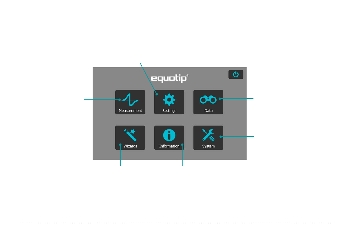
2.2 Main Menu
Table of Contents
On start up the main menu is displayed. All functions may be accessed directly via the Touchscreen. Return to the previous menu by pressing the
back button or the return icon (arrow) at the top left corner of the Touchscreen.
Settings: For application
specific settings, see chapter
“4. Settings”.
Measurement:
Measurement display screen,
see chapter “3. Measurement”.
Figure 3: Main Menu
6 © 2016 Proceq SA
Wizards: Task
related workflows, see
chapter “6. Wizards”.
Data (Explorer): File manager for
reviewing measurement data on the
instrument, see chapter “5. Data
(Explorer)”.
System: System settings,
e. g. language, display
options etc, see chapter
“8. System”.
Information: Operating
instructions and other
reference documents, see chapter
“7. Information”.
Page 7
3. Measurement
Table of Contents
3.1 Performing Measurements
3.1.1 Leeb Testing Procedure (except Leeb U)
Select automatic compensation for impact direction “Automatic”, see
chapter “3.2.1 Controls”. If “Automatic” is not allowed, set the impact
direction ( ). The Equotip Leeb Impact Devices DL doesn’t support automatic mode. The impact direction must be selected manually.
Select the appropriate material group, hardness scales and number of
impacts per measurement series. For more information see chapter “4.
Settings”. Conduct impacts by cycling through “load, position and trigger” mechanism:
1. Load the impact device – while not in
contact with the test piece – by holding it firmly with one hand and sliding
the loading tube with the other hand
until contact is grabbed by the clutch.
2. Position the support ring on the test
piece. Take particular care to fully
position the support ring on the test
piece, but not coinciding with a previous test indentation.
3. To trigger an impact, press the
trigger button to release the impact
body. To perform another impact,
repeat this cycle.
Figure 4: Leeb Testing Procedure
After the last of the impacts is performed, the hardness average and further statistics of the measurement series are displayed.
NOTE! Make sure the loading tube is allowed to slowly return
back to the starting position. Do take care so the loading
tube does not spring back uncontrolled, which may result in
permanent device damage.
NOTE! If possible, follow the standard practice of Leeb rebound hardness testing as described in the standards DIN
50156-1 (metallic materials), ASTM A956 (steel, cast steel and
cast iron only), or other applicable standards. If these are not
available, the user is recommended to average a minimum of
n = 3 impacts at an indentation distance of 3 to 5 mm (0.12
to 0.20”) for each location of the sample that shall be tested.
NOTE! Do not carry out an impact in an area that has already
been deformed by another impact. Also, do not load the device
when it is already positioned in the new test location, since the
material under the device may be affected through prior stress,
and the catch chuck of the device may get damaged.
© 2016 Proceq SA 7
Page 8
3.1.2 Portable Rockwell Testing Procedure
Table of Contents
1. Place the probe on the sample to
test. For flat surfaces the standard
foot is most suitable. For cylindrical
objects it is recommended to use
one of the special feet. For locations
difficult to access a tripod foot can
be used. See chapter “14. Ordering
Information” for more details.
2. Press the probe slowly but firmly
against the surface to perform the
measurement. Suppress vibrations
as much as possible, and follow the
instructions on the screen.
3. Release the probe when the instrument says so. Again, this movement
has to be done in a controlled manner. If the probe is released too fast,
a warning will be shown and the
measurement should be repeated.
Figure 5: Portable Rockwell Testing Procedure
3.1.3 UCI Testing Procedure
1. Place the probe on the sample to
test. The probe must be perpendicular to the surface (± 5°). The
special foot can be used to increase
repeatability and reduce distortion of the results, see chapter “14.
Ordering Information”.
2. Press the probe slowly but firmly
against the surface until the selected measuring force is reached.
The instrument will indicate when to
release the probe with an on-screen
prompt and audible sound.
3. Release the probe from the material. It is important to remove the
probe completely from the test
object. Otherwise the results can be
biased.
Figure 6: UCI Testing Procedure
NOTE! A warning will be shown if the user applied too much
load when pressing the probe against the surface. Please avoid
frequent overloading, as this could seriously damage the probe.
8 © 2016 Proceq SA
Page 9

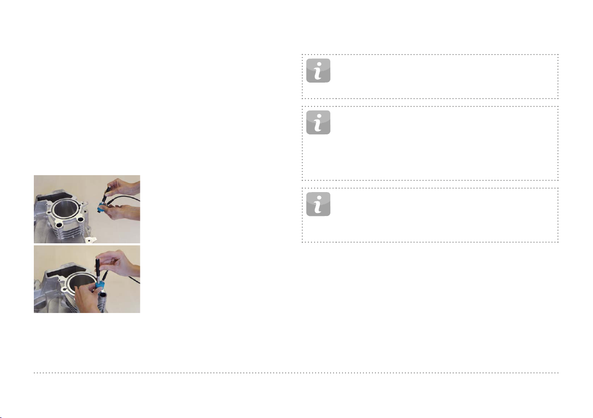
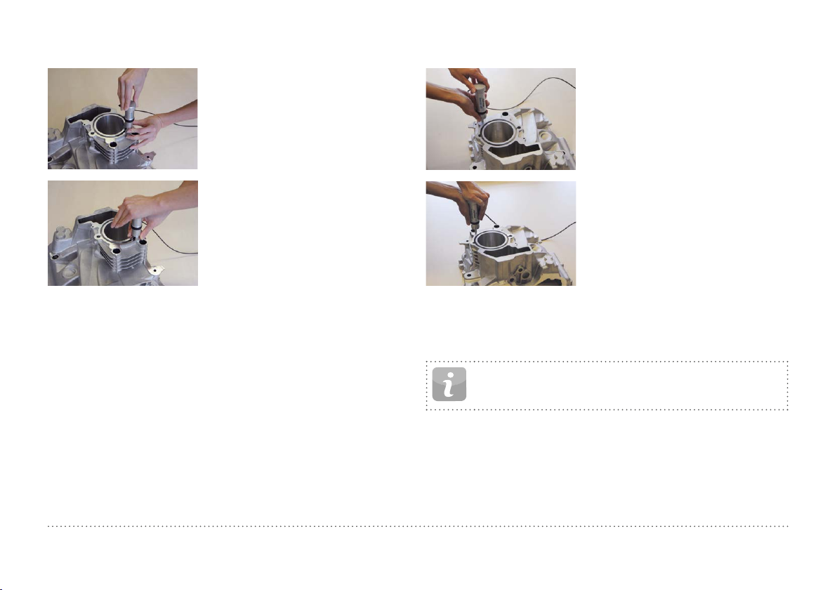
3.1.4 Leeb U Testing Procedure
Table of Contents
The Equotip 550 Leeb U enables the user to quickly and precisely diagnose roll imperfections, hardness inconsistencies and uneven winding,
thereby preventing problems for printing and converting operations.
With Equotip Impact Device Leeb U automatic impact direction mode is
not supported and the user must select the appropriate impact direction
manually (90° down, 45° down, 0°).
As for roll hardness testing no conversion curves are used, no material
group has to be selected.
Conduct impacts by cycling through “position and trigger”.
1. Position the probe on the roll to be
tested. Make sure to fully position the support ring on the roll to
ensure an impact perpendicular to
the test surface.
2. While holding the impact device
firmly with two hands, slide the
loading tube smoothly down to
load and trigger an impact.
Move the impact device to the next
point on the roll and repeat.
Figure 7: Leeb U Testing Procedure
NOTE! Some features mentioned in this Operating Instructions are specifically addressing metal hardness testing applications and therefore not available for Equotip Leeb U.
© 2016 Proceq SA 9
Page 10
3.2 Measurements Screen
Table of Contents
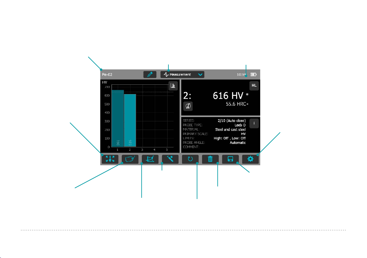
3.2.1 Controls
File Name: Enter the file name
and tap return. Saved measurements will be stored automatically. If filename management
is activated, this function is
locked.
Impact Direction: To
manually set the impact
direction if required
(Leeb only, by default
this is automatic).
Material: Select the
material group to use
for conversions (not
available for Leeb U).
Figure 8: Measurement Screen
10 © 2016 Proceq SA
Measurement Scale: Select the hardness
scale (primary and secondary) to be displayed
(not available for Leeb U).
Measurement Mode:
Switch between
measurement and conversion.
Wizards: Direct
access to wizards.
Redo: Restart the measurement series
or a single measurement.
Time and battery status
Settings: direct shortcut to
settings menu.
(only applicable to the
actual measurement series)
Save: Store measurement data.
Delete: Delete the last measurement.
Page 11
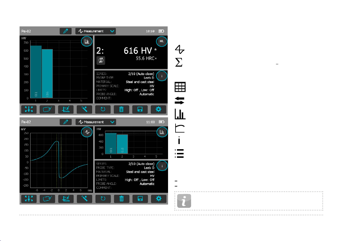
3.2.2 Measurement Views
HL
ID
+
Table of Contents
Equotip 550 is fully customizable as a device and can display three different measurement views simultaneously. Each view can be switched to
meet the user’s requirements by simply clicking on the icon related to the
particular display at the top right corner of each screen.
Signal View: Display the probe signal from the last active
measurement. This may be useful for advanced evaluations.
Statistic View: View statistics for the active measurement series. Number of impacts (n), Average (x), Standard deviation
(σ), Minimum/Maximum () and Range () are displayed in the
primary scale.
Table View: Display the measurements for the active series in
a table format.
Conversion View: Display the actual value on the conversion
curve.
Bar View: Display the measurements of the series as a histogram.
Profile View: Display the measurement results as a profile.
Info: Display the measurement settings e.g. series length,
probe type, material group etc.
User’s View: The user can choose between probe angle, mini-
mum, maximum, range and probe type for the field contents. To
change, tap on each individual box.
Single Record View: Display the last or selected measurement
result in both the primary and secondary hardness scales.
Sample ID’s: Defines the custom field.
Figure 9: Measurement Views
© 2016 Proceq SA 11
NOTE! Screen views cannot be duplicated.
Page 12
3.3 Measuring Methods
Table of Contents
Equotip 550 family of instruments is capable of accepting three diffrent
test methods using a single indicating unit.
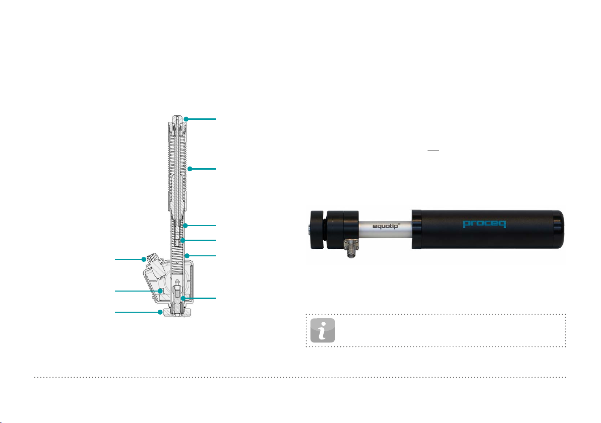
3.3.1 Equotip Leeb
3.3.1.1 Test Principle
Release button
Loading tube
Impact Spring
Catch chuck
Connection cable – 4 pole
Sensor of impact device with
ID ROM
Support ring
Figure 10: Schematic View of a Leeb Impact Device
Guide tube
Impact Body
During measurement with Equotip 550 impact devices (D, DL, DC, C,
G, S, and E); an impact body with a ball indenter is launched by spring
energy against the sample to be measured, and then rebounds. Before
and after the impact, a permanent magnet inside the impact body passes
through a coil in which a voltage signal is induced by the forwards and
backwards movement. This induction signal behaves proportionally to
the velocities. The ratio of the rebound velocity vr to the impact velocity vi
multiplied by 1000 yields the hardness value HL (Leeb hardness). HL is a
direct measure of the hardness. The third resp. fourth letter of the HL unit
refers to the impact device HLD D impact device.
v
r
HL =
·1000
v
i
Equotip Leeb U
Although the Equotip Leeb Impact Device U is constructed differently to
simplify the measurement process, the underlying principle is the same.
Figure 11: Equotip Leeb U Impact Device
Existing Parotester impact devices type U are fully supported by the
Equotip 550. Typ P and PG impact devices can be still used, but the unit
is shown as HLU although it would be actually LP resp. LPG.
NOTE! HLU values can be directly compared to LU on existing Parotester instruments.
12 © 2016 Proceq SA
Page 13
3.3.1.2 Sample Preparations
Table of Contents
Keep the sample free of vibrations during the test. Light and thin parts
must be specially fastened, see chapter “3.3.1.6 Testing Light Samples”.
Ensure that the surface of the work piece is clean, smooth and dry. If required, use appropriate cleaning agents for cleaning, such as acetone or
isopropanol. Do not use water or any other detergent fluids.
NOTE! Please use the surface roughness comparator plate
provided to estimate the average roughness of the test piece
prior to testing.
Figure 12: Surface Roughness Comparator Plate
3.3.1.3 Standards
Brief descriptions of referenced standards:
DIN 50156
ASTM A956
ASTM A370
ASTM E140
ISO 18265
ISO 16859
Leeb hardness testing of metallic materials
Standard test method for Leeb hardness testing of steel
products
Test methods and definitions for mechanical testing of
steel products
Standard hardness conversion tables for metals rela-
tionship among Brinell, Vickers, Rockwell, Superficial,
Knoop, Scleroscope and Leeb hardness
Metallic materials – Conversion of hardness values
Leeb hardness testing of metallic materials
© 2016 Proceq SA 13
Page 14

3.3.1.4 Test Conditions
Table of Contents
To ensure proper hardness readings, the following conditions must be fulfilled. If one or more conditions are not met, the measurement result may be
significantly false.
Impact device type D/DC/DL/S/E G C
Surface
preparation
Roughness grade class ISO 1302
Max. roughness depth R
Average roughness R
Minimum sample
mass
Of compact shape (kg / lbs)
On solid support (kg / lbs)
Coupled on plate (kg / lbs)
Minimum sample
thickness
Uncoupled (mm / inch)
Coupled (mm / inch)
Surface layer thickness (mm / inch)
Minimum space
Between indentation and sample edge
(mm/inch)
Between indentations (mm/inch) 3 / 0.12 4 / 0.16 2 / 0.08
Indentation size on
test surface
With 300 HV,
30 HRC
With 600 HV,
55 HRC
With 800 HV,
63 HRC
Table 1: Leeb Test Piece Requirements
(μm / μinch)
t
(μm / μinch)
a
Diameter (mm / inch)
Depth (μm / μinch)
Diameter (mm / inch)
Depth (μm / μinch)
Diameter (mm / inch)
Depth (μm / μinch)
N7 N9 N5
10 / 400 30 / 1200 2.5 / 100
2 / 80 7 / 275 0.4 / 16
5 / 11 15 / 33 1.5 / 3.3
2 / 4.5 5 / 11 0.5 / 1.1
0.05 / 0.2 0.5 / 1.1 0.02 / 0.045
25 / 0.98 70 / 2.73 15 / 0.59
3 / 0.12 10 / 0.4 1 / 0.04
0.8 / 0.03 0.2 / 0.008
5 / 0.2 8 / 0.3 4 / 0.16
0.54 / 0.021 1.03 / 0.04 0.38 / 0.015
24 / 960 53 / 2120 12 / 480
0.45 / 0.017 0.9 / 0.035 0.32 / 0.012
17 / 680 41 / 1640 8 / 2560
0.35 / 0.013 0.30 / 0.011
10 / 400 7 / 280
14 © 2016 Proceq SA
Page 15
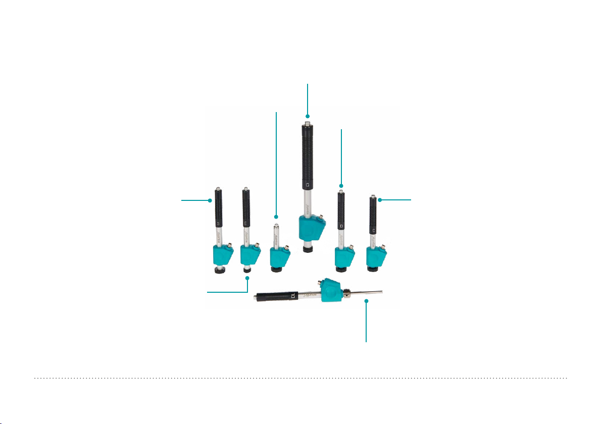
3.3.1.5 Selecting the Equotip Leeb Impact Device
Table of Contents
For optimized testing of diverse metallic materials and sample geometries, a range of impact devices are available as per “Table 1: Leeb Test Piece
Requirements”.
Type G: Increased impact energy. For solid and inhomogenous
components, e.g. heavy castings and forgings.
Impact energy: 90 Nmm
Type DC: Short device. For use in very
confined spaces, e.g. in holes, cylinders or
for internal measurements on assembled
machines. Impact energy: 11 Nmm
Type D: Universal unit. For the majority of
your hardness testing requirements.
Impact energy: 11 Nmm
Type S: Si3N4 ball indenter. For testing
especially in the very high hardness range
(in excess of 50 HRC / 650 HV): Tool steels
with high carbide content inclusions.
Impact energy: 11 Nmm
Figure 13: Equotip Leeb Impact Devices
© 2016 Proceq SA 15
Type E: Diamond ball indenter.
For testing in the very high hardness
range (in excess of 50 HRC / 650 HV):
Tool steels with high carbide content
inclusions. More durable than type S.
Impact energy: 11 Nmm
Type C: Reduced impact energy. Surface
hardened components, coatings, thin
walled or impact sensitive components
(small measuring indentation).
Impact energy: 3 Nmm
Type DL: Slim front section.
For measurements in confined spaces, at the
base of grooves or on recessed surfaces.
Impact energy: 11 Nmm
Page 16
3.3.1.6 Testing Light Samples
Table of Contents
If the samples are lighter than specified in chapter “3.3.1.4 Test Conditions” or sample sections have unfavorable mass distribution they can
vibrate as the impact body hits the test point. This results in unwanted
energy absorption. Such samples shall be supported by solid worktops.
If the mass falls below the specific requirements but still exceeds the
coupling amount then coupling it to a larger mass can help prevent vibrations.
The following requirements must be met for coupling:
• The contact surface of the sample and the surface of the solid support
must be level, flat and ground smooth.
• The sample must exceed the minimum sample thickness for coupling.
Follow the coupling procedure.
• Apply a thin layer of coupling paste to the contact surface of the sample.
• Press the sample firmly against the support.
• Push the sample in a circular motion and carry out the impact as usual,
perpendicular to the coupled surface.
NOTE! Clamping may strain the sample, which can affect the
hardness readings.
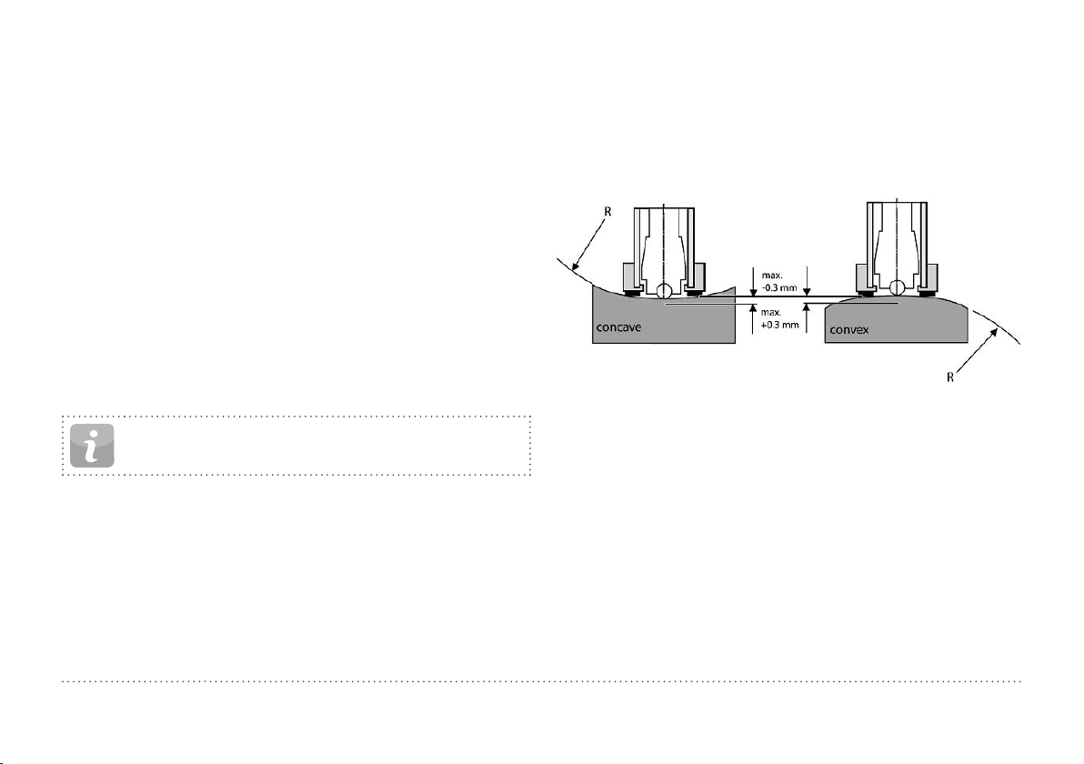
3.3.1.7 Testing Curved Surfaces
The instrument works properly only when the ball indenter at the front of
the impact body is precisely at the end of the tube at the time of the impact. When concave or convex surfaces are tested, the ball indenter either
does not entirely leave the test tube or comes out too far. In such cases,
replace the standard support ring by a specially suited ring, see chapter
“14. Ordering Information” or contact your local Proceq representative.
Figure 14: Leeb Testing on Curved Surfaces
16 © 2016 Proceq SA
Page 17

3.3.1.8 Testing Thin Samples
Table of Contents
Pipes and tubes sometimes have mass distributions that can affect the
result of the Leeb hardness test due to vibration. During on-site testing
of pipelines, for example the test locations cannot be supported by solid
worktops or clamped.
To benefit from the convenience and speed of the Leeb test, the user can
make use of a custom conversion after conducting the following calibration procedure, for example:
• Data pairs are measured on reference samples. For the Leeb HLDL reference measurements, it is crucial that they are done on parts that are
installed in the same way as those to be tested on-site. For example, two
pipe samples “Pipe type 5 mm Duplex soft” (730 HLDL / 255 HB) and
“Pipe type 5 mm Duplex hard” (770 HLDL / 310 HB) are measured using
the Equotip Leeb impact device DL and a Brinell tester, respectively.
• The original HLDL-HB conversion curve for “1 Steel and cast steel”
is now adapted using the two data points. The detailed procedure on
how to create custom conversion curves in the Equotip 550 is given in
chapter “6.4 Conversion Curve Creation”.
• To measure “Pipe type 5 mm Duplex” in future, it can be selected via
“Material” – “Pipe type 5 mm Duplex”, using the hardness scale “HB
Brinell” also see chapter “6.4.3 Example of a Custom Conversion (TwoPoint Method)”.
NOTE! The user needs to determine and qualify the adaptation of conversion curves for each tube diameter and wall
thickness. Guides to the procedure are provided in Nordtest
Technical Report Series 424, Reports 99.12/13 and ASME
Final Report CRTD-91.
3.3.1.9 Material Groups
No need to select any material when measuring in the native Leeb rebound scale HL as no conversion is applied. In contrast, hardness scale
conversions are correct only when the appropriate material group is selected. Free online material databases and the Equotip 550 on-board reference documents can be useful to assign your materials to one of the
default material groups. Suitability of conversions should be qualified on
calibrated samples before use. For further information, please consult a
Proceq representative.
NOTE! For a given test principle (native scale), the dropdown
menu only lists the material groups for which conversions
are available.
NOTE! If there is no conversion curve available, the user has
the possibility to create its their own, see chapter “6.4 Conversion Curve Creation”.
© 2016 Proceq SA 17
NOTE! It is important to include all the critical information
about the geometry of the test sample.
Page 18

D/DC DL S E G C
Table of Contents
Steel and cast steel
Cold work tool steel
Stainless steel
Cast iron lamellar graphite GG
Cast iron, nodular graphite GGG
Cast aluminium alloys
Copper/zinc alloys (brass)
CuAI/CuSn-alloys (bronze)
Wrought copper alloys, low alloyed
Table 2: Overview of Available Conversions
Vickers
Brinell
Rockwell
HV
HB
HRB
HRC
HRA
Shore
Rm N/mm²
HS
σ1
σ2
σ3
Vickers
RockwellHVHRC
Vickers
Brinell
Rockwell
HV
HB
HRB
HRC
Brinell
Vickers
Rockwell
Brinell
Vickers
Rockwell
Brinell
Vickers
Rockwell
Brinell
Rockwell
HB
HV
HRC
HB
HV
HRC
HB
HV
HRB
HB
HRB
81-955
81-654
38-100
20-68
30-99
275-2194
616-1480
449-847
80-900
21-67
85-802
85-655
46-102
20-62
90-664
90-698
21-59
95-686
96-724
21-60
19-164
22-193
24-85
40-173
14-95
80-950
81-646
101-964
101-640
37-100
21-68
22-70
61-88
31-97
275-2297
614-1485
449-849
80-905
21-67
28-104
340-2194
615-1480
450-846
104-924
22-68
* 119-934
105-656
70-104
21-64
* * * 92-326 *
* * * 127-364
20-187
21-191
20-184
22-196
* * * * *
84-1211
83-686
20-72
61-88
29-103
283-2195
616-1479
448-849
82-1009
23-70
88-668
87-661
49-102
20-64
23-176
22-198
90-646
48-100
305-2194
618-1478
450-847
* 98-942
* *
19-37
19-168
24-86
Brinell HB 60-290 * * * * *
Brinell HB 45-315 * * * * *
*Custom conversion curve / correlation
81-1012
81-694
20-70
30-102
275-2194
615-1479
450-846
20-67
*
21-167
23-85
18 © 2016 Proceq SA
Page 19

3.3.2 Equotip Portable Rockwell
Table of Contents
3.3.2.1 Test Principle
During measurement with Equotip 550 Portable Rockwell probe, a diamond
indenter is forced into the test piece, and then released back out of the material. The indentation depth is measured continuously during this process.
Indentation depth is calculated after decreasing the total load to preload.
10N
Figure 15: Portable Rockwell Test Principle
50N
10N
3.3.2.2 Sample Preparations
Ensure that the surface of the work piece is clean, smooth and dry. If
required, use appropriate cleaning agents for cleaning, such as acetone
or isopropanol. Do not use water or any other detergent fluids.
3.3.2.3 Measurement on Basis of DIN 50157
Both depth measurements d1 and d2 are taken at preload, first during
application (d1) then after release of the total load (d2). The difference between d1 and d2 originates from the deformation response of the material
to penetration.
NOTE! By calculating the penetration depth between the
preload and total load, surface roughness discrepancies are
significantly disregarded.
NOTE! The hardness testing principle in Portable Rockwell
follows the Rockwell stationary test. As for the Rockwell
test, no adjustment for the test direction is required. However, there are three main differences to traditional stationary
Rockwell tests:
• The test loads are lower.
• The Portable Rockwell indenter is sharper.
• The dwell times during the test are shorter.
NOTE! “MM” stands for “mobile mechanical” measurement,
an ancillary that is required by the German standard DIN
50157 to explicitly denote the lower applied loads, sharper
indenter shape and shorter loading times during a measurement. The different denomination is formal, i.e. the HMMRC
results should be very close if not equal to stationary HRC
readings.
© 2016 Proceq SA 19
Page 20

3.3.2.4 Test Conditions
Table of Contents
To ensure proper hardness readings, the following conditions must be
fulfilled. If one or more conditions are not met, the result may be significantly false.
3.3.2.5 Installing the Measuring Clamp
The clamp is designed to facilitate the hardness testing of very thin or
small samples.
Probe setup 50 N
probe
with
clamp
50 N probe
with round
standard
foot (ø =
42 mm)
Minimum test
piece thickness
Maximum test
piece thickness
Test piece surface
condition
40 mm N/A
recommended mean surface roughness
< 2 μm to minimize data scatter
R
a
1 mm at ~20 HB
130 μm at ~70 HRC
foot to be
Surface
curvature
used for
plane
surfaces
Maximum test
piece hardness
Minimum spacing
Table 3: Portable Rockwell Test Piece Requirements
three times the diameter of a test indentation
70 HRC
50 N
probe
with
tripod
very
small curvatures
acceptable
50 N probe
with special feet
18 – 70 mm
radius of
curvature or
70 mm – ∞
Cantilever
Cantilever screw
Knurled screw
Probe holder
Figure 16: Portable Rockwell Clamp
• Use the 3 mm Allen key setup tool to release the cantilever. Turn it by 90°.
• Take the probe and remove the foot. The diamond indenter remains
mounted.
• Screw the probe into the probe holder of the clamp clockwise (hand-tight).
• Turn the cantilever so its tip is centred over the probe; tighten the cantilever screw securely using the 3 mm Allen key setup tool.
• The recommended clearance between the bottom of the probe holder
and the sample surface should be between 2 and 5 mm. Adjust the
height with the two knurled screws.
20 © 2016 Proceq SA
Page 21

NOTE! In case the probe connector is in an inconvenient
Table of Contents
position, release the set screw. Ensure that the springs in
the mechanism do not get lost. Turn the mechanism into a
convenient position, aligning the set screw with the guide
channel. Lock the set screw so that the probe holder will still
slide up and down without rubbing on the set screw.
3.3.2.6 Considerations
• When measuring cylindrical samples with adapters Z4 or Z4+28, make
sure, the sample is not twisted on the clamp support. This is best
ensured when the back part of the clamp rests on a table and only the
sample support of the clamp sticks out over the table’s edge.
• When applying the load, slowly squeeze the leavers and allow the
sample to adjust to the support. During the measurement, do not
touch the sample, if possible. When releasing, grab the sample again.
• Whenever the sample geometry (i.e. the wall thickness) allows it, freehand measurements usually offer better measuring performance. This
applies particularly to measurements on cylinders.
• For small diameter rods (or stiff enough pipes), the V-notch clamp
adapter Z2 has been designed. When installing the Z2 support ensure
that the centre of the V-notch is centred underneath the probe holder.
3.3.2.7 Installation of Standard Foot or Tripod
The round standard foot permits measurements on test objects that are only
accessible from one side, such as large
metal sheets. The tripod is used when
the flat foot cannot be placed on the test
piece without wiggling.
1. The diamond indenter remains
mounted.
2. Install the foot on the probe.
Figure 17: Portable Rockwell
with Tripod
3.3.2.8 Installing the Special Foot
Two special feet extend the Portable Rockwell application range to cylindrical test pieces.
1. The diamond indenter remains
mounted.
2. Install the foot on the probe.
3. Place the foot on the test piece and
release the set screw on the foot.
Then press down the probe onto the
test piece and lock the set screw.
Figure 18: Portable Rockwell
Special Feet
© 2016 Proceq SA 21
Page 22

3.3.2.9 Conversion Standard
Table of Contents
Measurements in HV and HRC are direct correlations therefore no conversion is required. The user has the option of either ASTM E140 or ISO
18265 for conversion to any other scales.
3.3.3.2 Sample Preparations
Ensure that the surface of the work piece is clean, smooth and dry. If
required, use appropriate cleaning agents for cleaning, such as acetone
or isopropanol. Do not use water or any other detergent fluids.
3.3.2.10 Material Groups
Since Portable Rockwell is based on static indentation principle, the
hardness conversions are less dependent on material specific properties for the majority of times.
The user still has the possibility to apply customer conversion curves if
required, see chapter “6.4 Conversion Curve Creation”.
3.3.3 Equotip Ultrasonic Contact Impedance (UCI)
3.3.3.1 Test Principle
The UCI method uses the same pyramid-shaped diamond as a conventional Vickers hardness tester. Unlike Vickers testing, no optical evaluation of the indentation is required, enabling fast and portable measurements. The UCI method excites a rod into an ultrasonic oscillation. The
test load is applied by a spring and typically ranges from 1 to 5 kg of force
(HV1 – HV5). As the diamond is forced into the material, the frequency of
the rod oscillation changes in response to the contact area between the
diamond and the material under test. The instrument detects the shift in
frequency, converts it to a hardness value which is immediately displayed
on the screen.
3.3.3.3 Standards for UCI measurements
There are two standards which describe the UCI measurements, resp.
the instrument:
DIN 50159 Hardness testing with the UCI method
ASTM A1038 Standard test method for portable hardness testing by
the Ultrasonic Contact Impedance method
For conversions from one hardness unit to another, the user can chose
between the following standards:
ASTM E140 Standard hardness conversion tables for metals rela-
tionship among Brinell, Vickers, Rockwell, Superficial,
Knoop, Scleroscope and Leeb hardness
ISO 18265 Conversion of hardness values
22 © 2016 Proceq SA
Page 23

3.3.3.4 Test Conditions
Table of Contents
To ensure proper hardness readings, the following conditions must be fulfilled. If one or more conditions are not met, the result may be misleading.
Probe setup HV1 (~10 N) HV5 (~50 N)
Minimal required thickness
Minimal required weight
Required surface roughness
Acceptable surface curvature
Minimum space
Indentation size on test surface
300 HV, 30 HRC
600 HV, 55 HRC
800 HV, 63 HRC
Table 4: UCI Test Piece Requirements
Grade class N8 N10
Maximum roughness 15 μm / 600 μinch 60 μm / 2400 μinch
Average roughness 3.2 μm / 125 μinch 12.5 μm / 500 μinch
Indentation to edge 5 mm / 0.2 inch
Between indentations 3 mm / 0.12 inch
Depth 11.3 μm / 445 μinch 25.3 μm / 996 μinch
Diagonal 79.1 μm / 3114 μinch 177.1 μm / 6972 μinch
Depth 8 μm / 315 μinch 17.9 μm / 705 μinch
Diagonal 56 μm / 2205 μinch 125.3 μm / 4933 μinch
Depth 6.9 μm / 272 μinch 15.5 μm / 610 μinch
Diagonal 48.3 μm / 1900 μinch 108.5 μm / 4272 μinch
5 mm / 0.2 inch
0.3 kg / 0.66 lbs
Radius > 3 mm
© 2016 Proceq SA 23
Page 24

3.3.3.5 Installation of the Special Foot
Table of Contents
5 º
5º
The default foot allows the measurement to be performed on
every surface. The probe must be perpendicular to the surface (± 5°). The special foot can be used to increase the repeatability and avoid the distortion of the results, see chapter
“14. Ordering Information”.
1. Unscrew the standard foot and remove it
2. Screw the special foot to the probe tightly
NOTE! To measure in places with limited accessibility, the
probe can be used without any foot. If doing so, the side of
the rod of the probe must not touch any surface or be handled, as this leads to biased readings.
3.3.3.6 Conversions into Other Units
The frequency shift measured by the UCI probe is not only influenced by
the hardness, but also by its elastic properties. The default conversion curve
from the frequency shift to Vickers is valid for low-alloyed steel with an emodulus of 210 ± 10 GPa. As soon as a material has to be tested with a
different e-modulus, this existing conversion curve must be adapted. The
best way to do so is to calibrate the instrument on the material to be tested.
The Equotip 550 offers for this a fast and easy way. Once the hardness value
is converted to Vickers, it can be further converted to any other available
hardness unit according to either the ASTM E140 or the ISO 18265. Another
option is to adjust the default conversion based on the measurement of
Portable Rockwell or Leeb. To do so, see chapter “6.5 Combined Method”.
3.4 Instrument Verification / Daily Performance Check
See chapter “6.2 Device Verification” and follow the on-screen procedure. After the verification process your instrument is fully operational
and you can now continue with your measurements.
NOTE! The performance check should be done regularly before using the instrument to verify the mechanical and electronic functions of the probe and the indicating device. This
requirement is also included in the relevant hardness standards, see chapter “13. Standards & Guidelines”.
24 © 2016 Proceq SA
Page 25

4. Settings
Table of Contents
Figure 19: Settings Menu
4.1 Measurements
If changes are made here, they are set for all the upcoming measurement series. If the settings menu is accessed through the measurement
screen, changes are only valid for the actual measurement series.
4.1.1 Probe Type
Probe types are automatically recognised by the device. Default settings
can be set and will be used for each measurement device. If the measurement settings are accessed from the measurement screen, the active
probe can be selected.
4.1.2 Test piece management (Coming Soon)
Complete sets of settings can be managed in this menu. It allows the user to
save, edit, recall or delete these sets. This can be used to have a quick access
to different measurement settings, i.e. for different test pieces or applications.
4.1.3 Measurement Parameters
Material
The desired material group can be selected from the default list, in addition
you may predefine custom material groups which will be displayed here. For
custom material/curves please refer to chapter “6.4 Conversion Curve Creation”. For more information on material groups related to Leeb please refer to
chapter “3.3.1.9 Material Groups”, for Portable Rockwell chapter “3.3.2.10
Material Groups” and for UCI “3.3.3.6 Conversions into Other Units”.
Primary and Secondary scales
The user has the possibility to select two different scales in which the
measurement results are displayed.
NOTE! Conversion for HLD to HV, HB and HRC are standardized as per ASTM E140. Conversion for Portable Rockwell
(μm) and UCI can be switched between ASTM E140 and ISO
18265).
NOTE! Equotip Leeb Impact Device U does not support conversion curves, therefore these settings are not available.
Conversion Standards – Leeb
The conversion standard for Shore hardness HS switched between the
default conversion according to ASTM E448 or the Japanese conversion
according to JIS B7731.
NOTE! Measurements for certain types of Steel can be converted to tensile strength according to DIN EN ISO 18265.
Conversion Standards – Portable Rockwell
The default measuring method DIN 50157, is applicable for testing all
metallic material, and it generally yields more consistency. For conversions, user has the choice to select either ISO or ASTM.
© 2016 Proceq SA 25
Page 26

Conversion Standards – UCI
Table of Contents
The default measuring method is according to ASTM A1038 and DIN 50159.
For conversions, the user has the choice to select either ISO or ASTM.
Use Advanced Algorithm (Portable Rockwell only)
Advanced Algorithm provides faster measurements. This is especially
useful when testing softer material.
Impact direction (Leeb only)
With exception to DL and U devices all Leeb impact devices have automatic direction compensation. You may override this and set the impact
direction manually. For more information on impact direction please refer
to chapter “3.1.1 Leeb Testing Procedure (except Leeb U)”. Impact direction is not relevant to the Portable Rockwell and the UCI devices.
Trigger Load (UCI only)
For the Equotip UCI probe the load where the measurement will be triggered can be chosen in the range from HV1 to HV5 (10 – 50 N). The trigger load cannot be changed once the measurment series was started.
Units (Portable Rockwell only)
For Portable Rockwell probe, choose to display the indentation depth in
metric or imperial units.
4.1.4 Sample IDs
After Measurement
Use this setting to define if the current sample ID’s should be kept for the
next measurement series or deleted.
Edit Entries
The entries of the different sample ID fields can be deleted or edited here.
For easy increasing or decreasing, use the up- and down- arrows. For adding or removing entry fields, please see chapter “8.1.2 General Features”.
4.1.5 Workflow
Activate User Guidance
Select to display on screen instructions and messages when taking a
measurement.
Auto Close Series
Automatically end a series after a set number of measurements. The user
can set the series from 1 to 1000 measurements.
Measurement Comment Handling
Use this setting to allow or disallow the user to enter a comment at the
completion of a measurement series. When set to “free” this enables the
user inputing a comment.
Measurement Series Filename
Enter the file name for the measurement series will be stored. This possibility is disabled, if filename management is activated.
Save to Folder
Set the folder location where the measurement series file to be stored.
This option is disabled, if folder management is activated.
Store Signal Data (Leeb only)
Select to store the raw waveform for Leeb measurements. For Portable
Rockwell the signal form will be stored for each measurement automatically,
for UCI this option is not available..
NOTE! Storing signal data will cause measurement files to
take up more memory.
Enable Warnings
Choose to enable warning display signals and sounds to indicate false
measurements.
26 © 2016 Proceq SA
Page 27

Use report templates
Table of Contents
Here a template for the report can be selected. By default, the default
template will be used. This default template can be selected in the template manager.
Operator
Here the test operator can be edited. This operator name is stored for the
following measurements, but not for the verifications.
4.1.6 Limits
Enable Upper and Lower Limits
Select to enable the display of the upper and lower tolerance limits for the
measurements. Specific color coding is adopted to differentiate between
upper and lower limits.
4.2 Verification (Performance & Uncertainty Check)
To see how a verification can be performed please refer to chapter “6.2
Device Verification”.
4.2.1 Test Block Management
It is important to verify the correct functionality of the instrument on a
testblock calibrated in the genuine native scale of the probe being used.
In the test block management section, different test blocks information
can be stored. Test blocks that are listed here can then be used during
the verification process.
4.2.2 Workflow
Standard
Select the standard according to which the verification should be performed.
It can be selected between ISO, ASTM or a customer defined standard.
Minimum series count
The minimum required number of measurements can be selected here. If
a standard was selected before, this setting is fixed.
Maximum series count
The maximum allowed number of measurements can be selected here. If
a standard was selected before, this setting is fixed.
Operator reference
Here the reference operator name can be entered if required. This name
will be used for the verification processes. If no name is entered here, the
user can still enter it during the verification process.
NOTE! First time user: It is recommend to complete a “Tutorial on Leeb and Portable Rockwell Hardness Testing” as
appropriate or watch a demonstration by a qualified Proceq
representative.
NOTE! The performance check should be done regularly before each use of the instrument to verify the mechanical and
electronic functions of the impact device and the indicating device. This requirement is also included in the DIN and
ASTM Leeb hardness standards, see chapter “8.1 Features”.
4.2.3 Verification Standards and Extended Uncertainty
It is recommended for the instrument to be verified prior to testing. This
gives the user the extra assurance that the device is working correctly
and the measurement data are accurate. Although the verification process is similar on all Leeb, Portable Rockwell (mechanical penetration
depth) and UCI standards, user has the option to comply with the preferred standard/verification procedure.
© 2016 Proceq SA 27
Page 28

DIN 50156
Table of Contents
DIN 50157
DIN 50159
ASTM A956
ASTM A1038
ISO 16859
Extended
Uncertainty
(Combined
Uncertainty)
Leeb hardness testing of metallic materials. Will be replaced by ISO 16859.
Hardness testing of metallic materials with portable
measuring instruments operating with mechanical penetration depth.
Hardness testing with the UCI method.
Standard test method for Leeb hardness testing of steel
products.
Standard test method for portable hardness testing by
the Ultrasonic Contact Impedance method
Hardness testing of metalic materials by Leeb.
Measurement uncertainty analysis is applied to understand the differences in test results and to determine
sources of error. The uncertainty of an Equotip Leeb,
Equotip Portable Rockwell or Equotip UCI hardness
testing system consists of a statistical component, a
component inherent to the measurement device and a
component arising from the metrological chain between
national standard and the user device (traceability).
Although uncertainty could be a complicated topic,
Equotip 550 automatically calculates the combined uncertainty of the system. All the required information is already available in the calibration certificates provided by
Proceq. Therefore the device only requires adding these
values in the specified fields and following the simple
steps on the display in order to complete the process.
4.3 Conversions (Hardness Conversions)
There is no direct correlation between any two hardness scales. Therefore conversions must be determined by comparison testing for any
given alloy.
4.3.1 Standard Conversions
Proceq has developed correlations to convert the Leeb hardness measurements to other commonly used hardness scales based on groups
of alloys that have a close relationship. The conversions for HLD and
Material Group 1 (Carbon Steels) are standardized according to ASTM
E140-12b.
4.3.2 Custom Conversion Curves
See chapter “6.4 Conversion Curve Creation”.
4.3.2.1 Custom Compensation
In some cases a user must measure hardness on many samples with identical size and shape that is below the ideal limits for accuracy. Studies have
been published by ASME and Nordtest that have identified and confirmed
the validity of the strategy to apply a compensation factor to correct for the
inaccuracies induced by the non-ideal geometry. The methods outlined in
chapters “6.4 Conversion Curve Creation” can be applied to create this
compensation factor to be applied automatically to the Equotip test result.
4.4 Reporting
The content of the measurement reports can be adjusted here.
4.4.1 Images Explorer
Images, i.e. company logos can be loaded from an USB stick on the device, for use in reports. Pictures must be in the *.png or *.jpg format, ideally
come with 72dpi and a maximum resolution of 496x652 pixel.
Upload Images from an USB-stick
To do so follow the steps below.
• Create the folder “PQ-Import” in the main directory of the USB-stick
(not as a subfolder in another folder) and fill it with all the picture-files
to be uploaded to the Equotip Touchscreen
28 © 2016 Proceq SA
Page 29

• Connect the USB-stick to the USB Device plug on the left side of the
Table of Contents
Equotip Touchscreen
• Click on
• The uploaded images appear in the Images Explorer
and confirm with click on
NOTE! The USB stick must be either formatted in FAT or
FAT32. NTFS is not supported.
4.4.2 Report template explorer
The report templates can be managed here. Either the default template
can be used, or a fully customized template can be created and edited.
Templates can also be copied or exported to an USB stick.
4.4.3 Reporting via PDF
It’s possible to create reports directly on the instrument as PDF and store
them on USB stick. Choose the measurement files in the data explorer of
which a report should be created, mark them by ticking the box. Tap the
button to create the reports. The report will be created with the selected report template. Repeat this for each file. For each measurement
series there will be a separate PDF created.
NOTE! The report option is only visible if an USB stick is connected to the instrument. The USB stick must be either formatted in FAT or FAT32. NTFS is not supported.
Optionally, also the project file can be exported to the USB stick. Here all
files will be included in one file.
4.4.4 Reporting via Equotip Link
Alternatively to create reports the PC-Software Equotip Link can be used.
For more details please refer to chapter “11. Equotip Link Software”.
5. Data (Explorer)
Figure 20: Data Explorer Menu
5.1 Measurements
5.1.1 Storing Measurements
If the auto close option is disabled or chosen number of impacts is not
reached, the series can be closed and saved manually by tapping the
store button .
If the auto close option is enabled, the measurement series will be automatically stored as soon as the chosen number of impacts is reached.
The name under which the series will be stored can be edited in the upper left corner.
© 2016 Proceq SA 29
Page 30

NOTE! If the file name already exists, the name will be ex-
Table of Contents
tended by a number and increased with every additional file.
Tap on a saved file to open it and return to the Data Explorer list by pressing the back button.
The stored measurements can be organized in folders, by tapping the
Data Explorer button on the new folder option
Enter the name of the new folder and confirm by tapping on the back
button in the upper left corner.
The folder in which new measurements are stored can be selected under
Settings Measurement Save to Folder.
.
5.1.2 Data Explorer
From the main menu select Data Measurements to review and manage
saved measurements data.
Each folder and measurement series is shown as one line in the explorer
view.
For each series the probe used, mean value of the series, series name,
date & time of the measurement can be seen.
The list can be sorted by tapping on the corresponding header. The small
arrow indicates which list is sorted.
Figure 21: Measurement View in Data Explorer
5.1.3 Review of Data
In the detailed view of a measurement series, all information can be seen
and the settings are editable.
All the different views can be switched according to the users needs.
For more details about the different views, please refer to chapter “3.2.2
Measurement Views”.
5.1.4 Delete Files
From stored measurement files, single impacts can be eliminated afterwards. To do so, open the measurement series, tap the value to eliminate
and tap delete button .
Whole measurement files can be deleted in the Data Explorer. To do so,
tap on the box of the appropriate files to select and all selected files can
be deleted by tapping the delete button
To erase all data stored on the instrument, in the root folder tap on the
box on the left end of the header row then tap the delete button
.
.
30 © 2016 Proceq SA
Page 31

5.1.5 Copy Files
Table of Contents
To copy measurement series, select the file and click on the icon. Go
to the folder where the copy should be created and tap the icon to
paste the file. When copying a file all attributes will be duplicated
NOTE! The file cannot be added in the same folder!
5.1.6 Cut & Paste Files
To move existing measurement series from one place to another, set the
tick of the corresponding file and tap on the icon. Go to the folder
where the file should be moved in and tap the icon to paste the file
5.2 Verifications
From the main menu select “Data”, and then “Verifications” to review and
manage saved verification data “6.2 Device Verification”.
The verification data is stored and managed in the same manner as the
measurement data. Except no deletion is allowed.
Each folder and measurement series is shown as one line in the explorer
view.
Additionally the result for each verification data series, either a “passed”
or a “failed” is displayed.
6. Wizards
Figure 22: Wizards Menu
Wizards are a unique feature of Equotip 550. These simple step-by-step
instructions are for the majority of users, no matter how experienced they
are. Interactive wizards help speed up the workflow and improve the
measurement’s reliability.
All settings concerning wizards can be edited in the System User Settings. Also see chapter “8.1 Features”.
NOTE! For Equotip Leeb Impact Device U only the “Device
Verification” wizard is available.
© 2016 Proceq SA 31
Page 32

6.1 Measurement Wizard
Table of Contents
This particular wizard helps define the best measurement principle e.g.
impact device to fit the application, simply based on sample geometries
and surface conditions. To start, some basic information must be provided to define the test piece. When information is evaluated by the device
a series of recommendations are displayed in order of their relevance to
the application in question.
After the initial process is complete, the device recommends the appropriate probe, scope of application and preparation information. Settings
will then be adopted and the intelligent measurement process begins.
NOTE! Please verify that correct series number, impact direction, material group, scales and limits are defined as well as
sub file and folder name.
6.3 Impact Direction Calibration (Leeb only)
Each Leeb impact device requires a calibration in order to automatically
compensate for impact direction. This is easily achieved using this wizard.
NOTE! All impact devices are already factory calibrated when
shipped, however based on the usage and application it is
recommended to recalibrate the impact direction prior to
verification process chapter “6.2 Device Verification”. If this
process is not completed currently inaccurate data may be
obtained.
NOTE! This wizard can also be started from the menu System Probes.
6.2 Device Verification
During the verification process, the user will be guided through the entire procedure. At the end of the procedure the instrument is considered
verified and the data is stored in the device memory. Verification data is
also stored as the verification is performed, therefore any discrepancies
occurring over time will be noticeable.
32 © 2016 Proceq SA
NOTE! This wizard can also be started from the menu System Probes.
NOTE! A Proceq reference test block is required to complete
this wizard successfully.
6.4 Conversion Curve Creation
When default conversions are not suitable for the material being tested,
it is recommended to create a customized conversion/correlation. This
wizard guides the user through the complete process in a simple manner and provides all the necessary information on comparative measurements.
This creates a brand new conversion curve which is used for any future
measurements on the material in question.
6.4.1 Minimizing Conversion Errors
Conversion errors will not normally exceed ±2 HR for Rockwell scales
and ±10 % for Brinell and Vickers provided the material group is selected correctly. In most cases, the conversion error is significantly lower.
If higher accuracy is required or if the alloy under test is not covered by
one of the standard conversions, the Equotip 550 provides a variety of
methods to define material-specific conversions.
Page 33

6.4.2 Methods for Setting Up Custom Conversions
Table of Contents
The Equotip 550 provides three techniques to accomplish custom conversions, each can be used for all of the three different measuring principles (example HLD HRC):
One-point method: The Leeb hardness HLD and the hardness in the
desired scale (i.e. HRC) are determined for a reference work piece. A
standard conversion function HLD-HRC is then adapted through vertical
offset until the measured reference data pair lies on the shifted curve.
Two-point method: Two reference samples are tested, one as soft and
one as hard as possible to find two data pairs (i.e. HLD / HRC). A standard
conversion function HLD-HRC is then adapted through adding a straight
line until both of the measured reference data pairs lie on the tilted curve.
Conversion polynomial: If a custom conversion needs to be applied
throughout a wide hardness range, several reference samples shall be
tested to find a stable basis for interpolation. Up to 5th order polynomials
can be programmed into the Equotip 550 indicating device by defining
the polynomial coefficients A
HRC(HLD) = A
+ A1· HLD + A2· HLD2 + A
0
see Equotip Technical Guide under Information Documents or in the
download section of the Proceq website.
NOTE! When using a polynomial conversion of a higher order, please make sure to have the coefficients with sufficient
digits to avoid inaccuracies in calculations.
i
in
· HLD3 + A4· HLD4 + A5· HLD
3
5
6.4.3 Example of a Custom Conversion (Two-Point Method)
The data pairs (640 HLD / 41.5 HRC) and (770 HLD / 54.5 HRC) were
measured on two reference samples made from “special steel”.
To measure “special steel” in the future using an adapted HLD-HRC conversion, the original HLD-HRC conversion curve for “1 Steel and cast
steel” is tilted using the two data points. In this example, the special
conversion is defined as valid for the range 41 to 55 HRC.
Once this curve has been created, it can be selected via material group
“Customer defined” – “Special steel”, using the hardness scale “HRC
Rockwell C” also see chapter “3.3.1.8 Testing Thin Samples”.
Figure 23: Two-Point Conversion
© 2016 Proceq SA 33
Page 34

Figure 24: Custom Conversion Menu
Table of Contents
6.4.4 Measuring Reference Samples
Sample surfaces must be prepared very carefully and if possible, sample
shall met the specific geometries to avoid coupling method.
The functioning of the Equotip 550 shall be verified against the Leeb test
block prior to each measurement series.
The functioning of the static hardness testing machine (HMMRC, HV, HB,
HRC etc.) shall be verified against respective test blocks of the corresponding measuring scale and range.
To obtain a pair of comparative values, the mean value from at least 10
HL measurements and at least 3 values from the static test shall be calculated. These values shall be obtained from proximate positions in a
small measuring area depending on application.
6.5 Combined Method
The existing default hardness conversions in Equotip Leeb devices are
based on specific sample geometries. A Portable Rockwell probe has
almost no restriction with regard to thickness and mass. For samples that
don’t meet the Leeb specification, a simple custom correlation based on
the Portable Rockwell measurements enables the user to apply a correction factor and create a new hardness conversion. This is one example where the combined method is used to fit one measuring method
with the help of another one, for an application which is not covered by
the default setup. But there are several other occasions where this helpful tool offers great help. This can be achieved following the combined
method wizard on the Equotip 550. This wizard allows the combination of
the Leeb and Portable Rockwell, the UCI and Portable Rockwell and also
the combination of UCI with Leeb method. In each combination the later
mentioned method is the reference method.
This wizard guides the user in five simple steps through the whole process, and finally creates the conversion curve. For other applications it
can be used accordingly. For more information please see the “Equotip
Application Guide” on the Proceq homepage.
6.6 Mapping Wizard (Coming Soon)
The mapping wizard allows the user to create a 2-dimensional map with
readings. This is used to ‘scan’ a whole area. This wizard guides the user
in the whole process from defining the area, through the measurements
up to the final measuring report.
34 © 2016 Proceq SA
Page 35

7. Information
Table of Contents
Figure 25: Information Menu
7.1 Documents
All documentation files are stored in this section of the instrument and
can be viewed directly when required.
• Quick Start Guide: Gives an overview on the instrument including
scope of delivery.
• Operating Instructions: This document.
• Certificates: Certificates applicable to this product.
• Application Booklet: In-depth technical information on the different
measurement principles, its standards, influence of elevated temperatures, heavy use instructions and more.
• Platform Remote Control Package: Instructions are given on how
the instrument can be used with the remote control, i.e. for automation etc.
• More documents may be added at a later date.
NOTE! The last viewed document can be quickly accessed
by pressing the “Soft Key”. For more information see chapter
“2.1 Installation”.
7.2 Upload PDF-Files from an USB-stick
Additional documents in the PDF format can be stored on the instrument.
To do so follow the steps below.
• Create the folder “PQ-Import” in the main directory of the USB-stick
(not as a subfolder in another folder) and fill it with all the pdf-files to be
uploaded to the Equotip Touchscreen
• Go to Information/Documents
• Connect the USB-stick to the USB Device plug on the left side of the
Equotip Touchscreen
• Click on
• The uploaded PDF-files appear on the bottom of the document list
and confirm with click on
NOTE! The USB stick must be either formatted in FAT or
FAT32. NTFS is not supported.
© 2016 Proceq SA 35
Page 36

8. System
Table of Contents
Figure 26: System Menu
Verification Notification: Verification of the instrument can be set to
forced, optional or disabled. When set to disabled the user will not be
forced to perform an indirect verification. The setting “optional” is just a
reminder. If “forced” or “optional” is selected, an entry appears where the
verification interval may be chosen.
Custom Fields: The custom entry fields can be edited here. Beside the
five default fields which cannot be deleted, additional 20 fields can be
added.
8.1.3 Data Management
Use Folder Manager
Activate this option to use automatic folder management as configured
in the Folder Manager.
Folder Manager
Here the desired path can be edited. A maximum of four subfolders can
be created with selectable information. As soon as one of this information
changes, a new folder will be created automatically.
8.1 Features
8.1.1 Device Lock Settings
Lock/Unlock: Select this to lock the instrument and protect it from unintentional changes.
Password: A password can be set for the lock/unlock function. If this
field is left empty, no password is required to unlock the user settings.
8.1.2 General Features
Measurement Wizard: There are three options available on how the
measurements wizards are enforced.
36 © 2016 Proceq SA
Use File Manager
Activate this option to use automatic file naming as configured in the File
Manager.
File Manager
An automatic name can be configured here consisting of four different
information fields.
Long Filename Viewing
Choose here between a full view of the filename, or if only a selected
range should be displayed in the measurement screen. This setting influences only the name on the measurement screen, but not in the explorer
or reports.
Page 37

8.1.4 Probe Features
Table of Contents
For each probe type there is an option to protect its settings. Furthermore, for each probe type the different features to protect can be selected.
Factory reset: Select the options to delete all relevant data from the
device.
NOTE! This step cannot be undone, deleted items are permanently destroyed!
8.2 Probes
Information about the connected probe can be viewed here.
Angle calibration (Leeb only): The angle calibration for this particular
probe can be redone. This calibration can be done only for Equotip
Leeb Impact Devices.
Verification: Verification measurement series can be started here.
To see information about other used probes, tap on the
Probe Serial Number (only for Leeb U): As the serial number can not be
recognized automatically, the user has to enter it manually here.
button.
8.3 Hardware
General settings about the user interface and power options can be edited here.
Sound: The volume of the audio notifications of the instrument can be
adjusted respectively switched off.
Display: The user can adjust the brightness of the display backlight.
Power: The time after when the instrument dims the display, or shuts
down can be adjusted, for both battery and AC powered operation.
8.4 Date & Time
Date and time is set in this submenu. The format of these settings and the
time zone can also be modified.
8.5 Language
The language setting of the instrument can be selected. Eleven different
languages are available. The language of the help file is the same as for
the rest of the menu.
8.6 Device information
Tap the info button in the upper right corner to view all the information related to the device e.g. name, version and serial number can be
found in this section as well as battery status. On this information page
the IP address (if ethernet is connected and a DHCP server is available)
and the instruments MAC address will also be shown.
© 2016 Proceq SA 37
Page 38

9. Maintenance and Support
Table of Contents
9.1 Maintenance
The instrument should be calibrated annually to ensure consistent, reliable and accurate measurements. However, the service interval may be
based on actual experience and usage. Consult the applicable standards
for more guidance.
9.1.1 Regular Device Check
Performance checks, see chapter “4.2 Verification (Performance & Uncertainty Check)” of the instrument should be carried out at least once a day or
at the latest after 1000 impacts. In the case of infrequent use, carry out the
check before the beginning and at the end of a test series. In addition, have
the device calibrated by an authorized Proceq Service Center once a year.
NOTE! The unit is working properly when the average is
within the target range. Otherwise, please see chapter “10.
Troubleshooting”.
9.1.2 Cleaning
Leeb Impact device: Unscrew the support ring. Remove the impact
body from the guide tube. Clean the guide tube with the cleaning brush.
Reassemble.
Leeb Indenters: Clean the ball of the Leeb impact bodies and Portable
Rockwell diamond indenter with acetone or similar solvent. (Do not use
water or water based detergents!)
Portable Rockwell and UCI probes: Clean the probes and the diamond indenters with a clean, dry cloth.
Housing: Clean the display and housing with a clean, dry cloth after use.
Also clean the connector sockets with a clean, dry brush.
NOTE! Never immerse the device in water. Do not use compressed air, abrasives, solvents or lubricants to clean the
device.
9.1.3 Storage
Only store the Equotip 550 in the original packaging and in a dry room
free of dust.
9.1.4 Re-calibration for Impact Direction (Leeb only)
For Leeb impact devices the compensation function relies on parameters
specific to each impact device, which are stored in the device. Validity
of the active calibration can be checked through System Probes
Angle Calibration and then pressing the “Test” button. For each impact
direction, the deviation from the curve shall be less than ±0.2 Leeb (HL).
The parameters may change with time or due to external influences. Recalibration of the automatic compensation function in Equotip Leeb impact devices (except type DL) is recommended particularly when:
• Impact device has been cleaned, or
• Impact device has not been used for a long time, or
• Impact body has been replaced.
A re-calibration is done by consecutive selection of “0° (vertical down)”,
“90° (horizontal)” and “180° (vertical up)”.
9.1.5 Updating the Equotip 550 Operating System and
Application
Connect the device to the computer. Updates can be done using Equotip
Link as follows:
• Select update symbol
• Select “Express” and confirm with “Next”.
in Equotip Link
38 © 2016 Proceq SA
Page 39

• Select the device type and confirm with “Next”.
Table of Contents
• In the “Choose Communication Type” dialog box, select the type of
communication used between the Equotip and PC, and then click
“Next”.
• In the “Device search result and selection” dialog box, make sure the
serial number of the device in the drop-down field is the device to be
updated, and then click “Next”.
• PqUpgrade will now search the Proceq servers for any available updates. To do so, a working internet connection is required.
• Follow the on-screen instructions to finish the update.
NOTE! Although saved data is not deleted during the update
process, it is recommended to save the stored data in before
updating the firmware.
NOTE! The “Custom” update is recommended for advanced
users only.
9.2 Support Concept
Proceq is committed to providing a complete support service for this
instrument by means of our global service and support facilities. It is
recommended that the user register the product on www.proceq.com to
obtain the latest on available updates and other valuable information.
9.3 Standard Warranty and Extended Warranty
The standard warranty covers the electronic portion of the instrument
for 24 months from the date of purchase. The mechanical portion of the
instrument is covered by warranty for 6 months. An extended warranty
for an additional one, two or three years for the electronic portion of the
instrument may be purchased up to 90 days from the date of purchase.
9.4 Disposal
Disposal of electric appliances together with household waste is
not permissible. In observance of European Directives 2002/96/
EC, 2006/66/EC and 2012/19/EC on waste, electrical and electronic equipment and its implementation, and in accordance with national and local law, electric tools and batteries that have reached the end of
their life must be collected separately and returned to an environmentally
compatible recycling facility.
© 2016 Proceq SA 39
Page 40

10. Troubleshooting
Table of Contents
10.1 Incorrect Measurements / Failed Performance Check
10.1.1 Leeb
During the performance check, if the average deviates from the set point
value by more than ± 6 HL (for Leeb U ± 12 HLU):
• Check first that the test block is clean, smooth and dry. See chapter
“3.3.1.2 Sample Preparations”. Replace the test block if there is insufficient space for additional tests.
• Clean the impact body, paying close attention to the indenter ball at
the bottom and to the catch pin at the top of the body. Replace the
impact body if necessary.
• Clean the impact device.
• Check the mounting and wear of the support ring. Check for deposits.
Clean or replace if necessary.
• The incorrect material group, hardness scale or a wrong setting for the
impact direction may have been selected. Refer to chapter “4. Settings”.
• The selected hardness scale is not in the permissible range (no conversion). Select another scale.
• Check if individual values are scattered very widely or are continuously
too low.
• The impact is triggered while the device is not held vertically on the
surface. This may occur especially when using impact device DL. Try
using the plexiglass sleeve DL for better alignment.
• Sample is insufficiently supported. Prepare the sample for the impact
e.g. through use of the coupling method, see chapter “3.3.1.6 Testing
Light Samples”.
• If the instrument still shows excessive deviations: return the device
to an authorized Proceq Service Centre for recalibration / inspection.
NOTE! Do not resurface test blocks or try to refurbish impact
bodies. This will impair accuracy and may also deteriorate
functionality of the Equotip 550.
10.1.2 Portable Rockwell
During the performance check, if the average deviates from the set point
value by more than ±2 HRC:
• Confirm the foot is seated securely on the probe or the probe securely
in the clamp, respectively.
• Clean the indenter, paying close attention especially to the front part
(diamond) and to the screw thread.
• Check that the test block is clean, smooth and dry. See chapter
“3.3.2.2 Sample Preparations”. Replace the test block if there is insufficient space for additional tests.
• Check the mounting and wear of the stand and clamp. Check for deposits. Clean or replace if necessary.
• An incorrect conversion may have been selected. See chapter”4. Settings”.
• The selected conversion scale is not in the permissible range (“no conversion”). Select another hardness scale
• The test is conducted while the device is not held vertically on the surface, which will generally give a warning on the guidance dialog. This
may occur especially when using tripod. Try using another foot, or take
more care to align the probe vertically to the surface.
• Test piece is insufficiently supported. Prepare the test piece for the test
e.g. through supporting it with a larger metal piece.
• Make sure the probe does not tilt / move on the surface. See chapter
“3.3.1.7 Testing Curved Surfaces”.
• If the instrument still shows excessive deviations: return the device
to an authorized Proceq Service Centre for recalibration / inspection.
40 © 2016 Proceq SA
Page 41

NOTE! Do not resurface test blocks or try to use non-Proceq
Table of Contents
indenters. This will impair accuracy and may also deteriorate
functionality of the Portable Rockwell.
10.1.3 UCI
The allowable tolerances for the UCI performance test differ depending
on the selected standard. According to the DIN 50159 it should typically
not differ more than 5% from the given value. This tolerance is getting
wider for harder test blocks. The Equotip 550 considers these limits according to the standard.
According to the ASTM A1038 the values may not deviate by more than
3%, no matter what hardness is tested.
• Check to have the correct settings selected, i.e. no conversion activated.
• Clean the indenter, paying close attention especially to the front part
(diamond).
• Check that the test block is clean, smooth and dry. See chapter
“3.3.3.2 Sample Preparations”. Replace the test block if there is insufficient space for additional tests.
• Check the mounting and wear of the special foot. Check for deposits.
Clean or replace if necessary.
• If the test was conducted while the device was not held vertically on
the surface, the reading can be misleading. This may occur especially
when using the standard foot. Try using the special foot, or take more
care to align the probe vertically to the surface.
• Test piece is not fulfilling the geometry requirements or is insufficiently
supported. Check chapter “3.3.3.4 Test Conditions” for the minimum
requirement. Prepare the test piece for the test i.e. by supporting it
with a larger metal piece.
• If the instrument still shows excessive deviations: Return the device
to an authorized Proceq Service Centre for recalibration / inspection.
NOTE! Do not resurface test blocks.
10.2 No Reading Displayed
• Check the connection of the probe.
• Check if a genuine Equotip impact body (with the engraving “equo”) is
inserted in the impact device by unscrewing the support ring.
• Check for tight seating of the support ring on the thread of the impact
device.
• Check for tight seating of the support ring on the thread of the impact
device.Check whether the impact body is armed and released when
conducting the load – trigger procedure. If not, the catch chuck of the
impact device may be broken or the impact body is inserted upsidedown. Insert the impact body correctly or replace the impact device
with a basic Equotip Leeb impact device.
© 2016 Proceq SA 41
Page 42

10.3 Battery
Table of Contents
If the indicating device does not switch on, recharge the battery using the
power supply, see chapter “2.1 Installation”.
The battery can be replaced with another Equotip Lithium-Ion battery.
NOTE! If the operation time of the battery is shortening noticeably, order a new battery. The battery lifetime has expired
when the LED does not go off even though the battery has
been charged for several days.
Danger: Only use the power supply (12 V, 5 A) to charge the
Equotip 550.
10.4 Touchscreen Calibration
In very seldom cases, or when a protective screen foil is used, it can be
necessary to re-calibrate the Equotip 550.
To do so, press and hold the middle hardware button (Fullscreen) for 10s.
During the calibration process, don’t touch the display unit, as it can bias
the calibration.
11. Equotip Link Software
11.1 Starting Equotip Link
Locate the file “Equotip Link Setup.exe” on your computer or on
the DVD and click on it. Follow the instructions on the screen.
Make sure that the “Launch USB Driver install” tick is selected.
Double click on the Equotip Link Icon on your desktop or start the program
via the start menu.
11.2 Application Settings
The menu item “File – Application settings” allows the user to select the
language and the date and time format to be used.
42 © 2016 Proceq SA
Page 43

11.3 Connecting to an Equotip 550 Touchscreen Unit
Table of Contents
Connect the Equotip 550 Touchscreen Unit to an USB port or connect
it to the Ethernet (DHCP server requried)., then select to download
data from the Equotip 550 Touchscreen Unit.
The following window will be displayed: Select the appropriate communication type. If connecting through Ethernet, please enter the instruments
IP address in the appropriate field. Click on “Next >”.
When an Equotip 550 has been found its details will be displayed on
screen. Click on the “Finish” button to establish the connection
Measurement files and folders stored on the
Equotip Touchscreen will be displayed as shown
on the left.
Click on the measurement file to be transferred. If
multiple files have to be transferred, select them
while holding the “shift”or “ctrl” button, or click on
“Select All”.
11.4 Connection to Portable Rockwell Probe
• Connect the Portable Rockwell probe to a PC using the provided
probe cable.
• Start the Equotip Link software, and click on the Portable Rockwell
icon
to detect the Portable Rockwell probe. Click the “New” button
at the bottom of the screen.
• Select the hardness scale to be displayed (Hardness scales).
• Select the number of readings “n” per measurement series.
11.4.1 Viewing Data
The transferred measurements from your Equotip 550 will be displayed
on the screen:
Click on the double arrow icon in the first column to see more details.
11.5 Adjusting the Settings
“All settings, such as material group, scale, impact direction and both
limits can be changed afterwards in Equotip Link.
If the settings of multiple measurement series have to changed, select
each of them while holding the “shift” or “ctrl” button.
© 2016 Proceq SA 43
Page 44

11.5.1 Adjusting Date and Time
Table of Contents
Right click in the “Date & Time” column.
The time will be adjusted for the selected series only.
11.6 Exporting Data
Equotip Link allows you to export selected objects or the entire project.
To use the data for further analysis in a third party program, such as e.g.
Microsoft Excel, it can be exported as a comma separated file (CSV). To
use it directly in a report, the series data can be exported as a graphic.
As a third option, selected series data can be printed out directly on a
printer.
Click on the “Export as CSV file(s)” icon. The data is then
exported as a Microsoft Office Excel comma separated file.
The export options may be chosen in the following window:
Click on the “Export as graphic” icon to open the following window which allows the various export options to be
chosen.
Click on the printer icon to directly print a report of the selected
measurement series.
44 © 2016 Proceq SA
Page 45

11.7 Exporting and Importing of Setting Profiles
Table of Contents
To transfer all the selected settings from one instrument to another, or
to back up, click on “Equotip – Download device application settings”.
The actual settings will be stored in the specified folder on the PC as an
archive.
To re-install stored settings, click on “Equotip – Upload device application settings”.
11.8 Exporting and Importing of Conversion Curves
Custom conversion curves created on the instrument can be downloaded to the PC by clicking on “Equotip - Download customer conversion”.
All available customer conversions from the instrument will be stored on
the PC in the folder ...\Proceq\EquotipLink\Conversions.
To upload a conversion curve from your PC, choose “Equotip - Upload
customer conversions”. This is also possible for existing Equotip3 conversion curves.
12. Technical Specifications
12.1 Instrument
Display 7” color display 800x480 pixels
Memory Internal 8 GB Flash memory
(up to 1’000’000 measurements)
Regional settings Metric and Imperial units, multi-language
and timezone supported
Battery Lithium Polymer, 3.6 V, 14.0 Ah
Battery lifetime > 8h (in standard operating mode)
Power input 12 V +/-25 % / 1.5 A
Weight (of display device) About 1525 g (incl. Battery)
Dimensions 250 x 162 x 62 mm
Max. altitude 2’500 m above sea level
Humidity < 95 % RH, non condensing
Operating temperature 0 to 30°C (32 to 86°F)
(Charging, running instrument)
0 to 40°C (32 to 104°F)
(Charging, instrument is off)
-10 to 50°C (14 to 122°F)
(Non-charging)
Environment Suitable for indoor & outdoor use
IP classification IP 54
Pollution degree 2
Installation category 2
© 2016 Proceq SA 45
NOTE! Charging equipment is for indoor use only (no IP classification).
Page 46

12.2 Power Supply
Table of Contents
Model HK-AH-120A500-DH
Input 100-240 V / 1.6 A / 50/60 Hz
Output 12 V DC / 5 A
Max. altitude 2500 m above sea level
Humidity < 95%
Operating temperature 0 - 40°C (32 to 104°F)
Environment Indoor use only
Pollution degree 2
Installation category 2
12.3 Equotip Leeb Impact Devices
Measuring range 1-999 HL
Measuring accuracy ± 4 HL (0.5 % at 800 HL)
± 6 HLU (for Leeb U)
Resolution 1 HL; 1 HV; 1 HB; 0.1 HRA; 0.1 HRB; 0.1 HRC;
0.1 HS; 1 MPa (N/mm2)
Impact direction Automatic compensation (excl. DL/U probe)
Impact energy • 11.5 Nmm for D, DC, E, S probes
• 11.1 Nmm for DL probe
• 3.0 Nmm for C probe
• 90.0 Nmm for G probe
• 200.0 Nmm for U probe
Mass of impact body • 5.45 g (0.2 ounces) for D, DC, E, S probes
• 7.25 g (0.26 ounces) for DL probe
• 3.10 g (0.11 ounces) for C probe
• 20.0 g (0.71 ounces) for G probe
• 26.0 g (0.92 ounces) for U probe
Ball indenter • Tungsten carbide, 3.0 mm (0.12“) diameter
for C, D, DC probes
• Tungsten carbide, 2.78 mm (0.11“) diameter
for DL probe
• Tungsten carbide, 5.0 mm (0.2“) diameter
for G probe
• Ceramics, 3.0 mm (0.12”) diameter for S
probe
• Polycrystalline diamond, 3.0 mm (0.12”)
diameter for E probe
• Hardened Steel, 50.0 mm (1.97”) diameter
for U probe
Operating temperature -10 to 50˚C (14 to 122°F)
46 © 2016 Proceq SA
Page 47

12.4 Equotip Portable Rockwell Probe
Table of Contents
Dimensions 112 x ø 40 mm (4.4 x ø 1.57 inches
without foot)
Weight 260 g (9.17 oz)
Power supply Via USB (5 V, max. 100 mA)
Measuring range 0-100 μm; 19-70 HRC; 34-1080 HV
Measuring accuracy 1.5 HRC according to DIN 50157
Resolution 0.1 μm; 0.1 HRC; 1 HV
Test direction Any direction (no correction required)
Test loads 10 N / 50 N (probe 50 N)
Diamond indenter Angle 100.0° ± 0.5°
Operating temperature 0 to 50°C (32 to 122 °F)
Humidity Non-condensing, 90% max.
12.5 Equotip UCI Probe
Dimensions 155 x ø 40 mm (6.1 x ø 1.57 inches) with-
out foot
Weight 270 g (9.52 oz)
Power Supply via Proceq Interface
Measuring Range 20 – 2000 HV
Measuring accuracy ± 2 % (150 – 950 HV)
Resolution 1 HV; 0.1 HRC
Test direction Any direction (no correction required)
Trigger loads Selectable: HV1 (~10N), HV2 (~20N),
HV3 (~30N), HV4 (~40N), HV5 (~50N)
Diamond indenter Vickers diamond according to ISO 6507-2
Operating temperature 0 to 50°C (32 to 122°F)
Humidity Non-condensing, 90% max.
13. Standards & Guidelines
• ISO EN 16859
• ISO 18265
• DIN 50156 / 50157 / 50159
• ASTM A956 / E140 / A370 / A1038
• DGZfP Guideline MC 1
• VDI / VDE Guideline 2616 Paper 1
• Nordtest Technical Report Series 424, Reports 99.12 / 99.13 / 99.36
• ASME CRTD-91
• GB/T 17394
• JB/T 9378
• JJG 747
• JIS B7731
© 2016 Proceq SA 47
Page 48

14. Ordering Information
Table of Contents
14.1 Units
Part No. Description
356 10 001 Equotip 550 consisting of Equotip Touchscreen incl.
Battery, Power Supply, USB-Cable, Surface Roughness
Comparator Plate, DVD with Software, Documentation,
Carrying Strap and Carrying Case
356 10 002 Equotip 550 Leeb D consisting of Equotip Touchscreen
incl. Battery, Equotip Basic Leeb Impact Device D, Impact Body D, Support Rings (D6,D6a), Cleaning Brush,
Impact Device Cable, Test Block ~775 HLD / ~56 HRC,
Coupling Paste, Power Supply, USB-Cable, Surface
Roughness Comparator Plate, DVD with Software,
Documentation, Carrying Strap and Carrying Case
356 10 003 Equotip 550 Leeb G consisting of Equotip Touchscreen
incl. Battery, Equotip Basic Leeb Impact Device G, Impact Body G, Support Rings (G6,G6a), Cleaning Brush,
Impact Device Cable, Test Block ~570 HLG /~340 HB,
Coupling Paste, Power Supply, USB-Cable, Surface
Roughness Comparator Plate, DVD with Software,
Documentation, Carrying Strap and Carrying Case
356 10 004 Equotip 550 Portable Rockwell consisting of Equotip
Touchscreen incl. Battery, Equotip Portable Rockwell
Probe 50 N, Protective Rubber Sleeve, Probe Cable,
Test Block ~62HRC, Power Supply, USB-Cable, Surface Roughness Comparator Plate, DVD with Software,
Documentation, Carrying Strap and Carrying Case
356 10 005 Equotip 550 UCI consisting of Equotip Touchscreen
incl. Battery, Equotip UCI Probe HV1-HV5, UCI Probe
Cable, UCI Test Block ~850 HV, Power Supply, USBCable, Surface Roughness Comparator Plate, DVD with
Software, Documentation, Carrying Strap and Carrying
Case
356 10 006 Equotip 550 Leeb U (for paper, film and foils) consisting
of Equotip Touchscreen incl. Battery, Equotip Leeb
Impact Device U, Cleaning Brush, Probe Cable,
Power Supply, USB-Cable, DVD with Software,
Documentation, Carrying Strap and Carrying Case
356 10 020 Equotip 550 Portable Rockwell & UCI Kit consisting
of Equotip 550 UCI (356 10 005) and Equotip Portable
Rockwell Probe 50 N (356 00 600)
356 10 021 Equotip 550 Portable Rockwell & Leeb D Kit consist-
ing of Equotip 550 Leeb D (356 10 002) and Equotip
Portable Rockwell Probe 50 N (356 00 600)
356 10 022 Equotip 550 Leeb D & UCI Kit consisting of Equotip
550 Leeb D (356 10 002), Equotip UCI Probe HV1-HV5
(356 00 700) and Equotip UCI Test Block ~850 HV, ISO
6507-3 HV5 Calibration (357 54 100)
14.2 Impact Devices & Probes
Part No.
356 00 500 Equotip Leeb Impact Device C
356 00 100 Equotip Leeb Impact Device D
356 00 110 Equotip Leeb Impact Device DC
Description
Impact Device incl. Support Ring, Impact Body, Cable
48 © 2016 Proceq SA
Page 49

356 00 120 Equotip Leeb Impact Device DL
Table of Contents
356 00 400 Equotip Leeb Impact Device E
356 00 300 Equotip Leeb Impact Device G
356 00 200 Equotip Leeb Impact Device S
360 04 600 Equotip Leeb Impact Device U
Impact Device only
353 00 501 Equotip Basic Leeb Impact Device C
353 00 101 Equotip Basic Leeb Impact Device D
353 00 111 Equotip Basic Leeb Impact Device DC
353 00 121 Equotip Basic Leeb Impact Device DL
353 00 401 Equotip Basic Leeb Impact Device E
353 00 301 Equotip Basic Leeb Impact Device G
353 00 201 Equotip Basic Leeb Impact Device S
360 04 032 Equotip Basic Leeb Impact Device U
356 00 600 Equotip Portable Rockwell Probe 50N
(for Equotip 550 or PC)
356 00 700 Equotip UCI Probe HV1-HV5
14.3 Parts and Accessories
Part No. Description
327 01 043 Carrying Strap complete
327 01 033 Battery complete
351 90 018 USB-Cable 1.8 m (6 ft)
327 01 061 Power Supply
711 10 013 Power Supply Cable USA 0.5 m (1.7 ft)
711 10 014 Power Supply Cable UK 0.5 m (1.7 ft)
711 10 015 Power Supply Cable EU 0.5 m (1.7 ft)
327 01 053 Quick Charger
356 00 081 Equotip Surface Roughness Plate
350 01 015 Equotip Coupling Paste
356 00 082 Display Antiglare Protection Film for Touchscreen Unit
356 00 080 Equotip Leeb Impact Device Cable 1.5 m (5 ft)
353 00 086 Equotip Leeb Impact Device Extension Cable 5 m (15 ft)
356 00 083 Equotip Leeb Impact Device U Cable 1.5 m (5 ft)
350 01 004 Equotip Impact Body D/DC
350 71 311 Equotip Impact Body DL
350 71 413 Equotip Impact Body S
350 08 002 Equotip Impact Body G
350 07 002 Equotip Impact Body E
350 05 003 Equotip Impact Body C
360 04 504 Equotip Impact Body U
350 01 009 Equotip Support Ring D6
350 01 010 Equotip Support Ring D6a
350 08 004 Equotip Support Ring G6
© 2016 Proceq SA 49
Page 50

350 08 005 Equotip Support Ring G6a
Table of Contents
350 71 314 Equotip Support Ring DL
360 04 531 Equotip Support Ring U
353 03 000
350 01 008
350 08 006 Equotip Leeb Impact Device Cleaning Brush G
360 04 502 Equotip Leeb Impact Device Cleaning Brush U
350 01 007 Equotip Leeb Impact Device DC Loading Stick
350 71 316 Equotip Leeb Impact Device DL Plexiglas Sleeve
360 04 530 Assembly Gauge for Equotip Leeb Impact Device U
354 01 139 Equotip Portable Rockwell Probe Cable 2 m (6 ft)
354 01 200 Equotip Portable Rockwell Measuring Clamp
354 01 130 Equotip Portable Rockwell Tripod
354 01 250 Equotip Portable Rockwell Special Foot RZ 18 - 70
354 01 253 Equotip Portable Rockwell Special Foot RZ 70 - ∞
354 01 137 Equotip Portable Rockwell Protective Rubber Sleeve
354 01 243
354 01 229
Set of Support Rings (12pcs) for Equotip Leeb Impact
Device D/DC/C/E/S
Equotip Leeb Impact Device Cleaning Brush
D/DC/C/E/S
Equotip Portable Rockwell support Z2 for measuring
clamp
Equotip Portable Rockwell Support Z4+28 for
measuring clamp (for tubes and pipes over Ø 28 mm)
354 01 228
356 00 720 Equotip UCI Special Foot
Equotip Portable Rockwell support Z4 for measuring
clamp (for tubes and pipes up to Ø 28 mm)
14.4 Test Blocks
Part No. Description
357 11 500 Equotip Test Block C, ~565 HLC / <220 HB,
Proceq Factory Calibration
357 12 500 Equotip Test Block C, ~665 HLC / ~325 HB,
Proceq Factory Calibration
357 13 500 Equotip Test Block C, ~835 HLC / ~56 HRC,
Proceq Factory Calibration
357 11 100 Equotip Test Block D/DC, <500 HLD / <220 HB,
Proceq Factory Calibration
357 12 100 Equotip Test Block D/DC, ~600 HLD / ~325 HB,
Proceq Factory Calibration
357 13 100 Equotip Test Block D/DC, ~775 HLD / ~56 HRC,
Proceq Factory Calibration
357 13 105 Equotip Test Block D/DC, ~775 HLD, one side,
Proceq Factory Calibration
357 11 120 Equotip Test Block DL, <710 HLDL / <220 HB,
Proceq Factory Calibration
357 12 120 Equotip Test Block DL, ~780 HLDL /~325 HB,
Proceq Factory Calibration
357 13 120 Equotip Test Block DL, ~890 HLDL / ~56 HRC,
Proceq Factory Calibration
50 © 2016 Proceq SA
Page 51

357 13 400 Equotip Test Block E, ~740 HLE / ~56 HRC,
Table of Contents
Proceq Factory Calibration
357 14 400 Equotip Test Block E, ~810 HLE / ~63 HRC,
Proceq Factory Calibration
357 31 300 Equotip Test Block G, <450 HLG / <200 HB,
Proceq Factory Calibration
357 32 300 Equotip Test Block G, ~570 HLG / ~340 HB,
Proceq Factory Calibration
357 13 200 Equotip Test Block S, ~815 HLS / ~56 HRC,
Proceq Factory Calibration
357 14 200 Equotip Test Block S, ~875 HLS / ~63 HRC,
Proceq Factory Calibration
360 04 503 Equotip Test Block U, ~560 HLU,
Proceq Factory Calibration
357 41 100 Equotip Portable Rockwell Test Block ~20 HRC,
ISO 6508-3 HRC Calibration
357 42 100 Equotip Portable Rockwell Test Block ~45 HRC,
ISO 6508-3 HRC Calibration
357 44 100 Equotip Portable Rockwell Test Block ~62 HRC,
ISO 6508-3 HRC Calibration
357 51 100 Equotip UCI Test Block ~300 HV, ISO 6507-3 HV5
Calibration
357 52 100 Equotip UCI Test Block ~550 HV, ISO 6507-3 HV5
Calibration
357 54 100 Equotip UCI Test Block ~850 HV, ISO 6507-3 HV5
Calibration
Test Blocks Calibrations
Part No. Description
357 10 109
357 10 129 Equotip Leeb Test Block Additional Calibration HLDL
357 10 209 Equotip Leeb Test Block Additional Calibration HLS
357 10 409 Equotip Leeb Test Block Additional Calibration HLE
357 10 509 Equotip Leeb Test Block Additional Calibration HLC
357 30 309 Equotip Leeb Test Block Additional Calibration HLG
357 90 909
357 90 919
357 90 929
357 90 939
357 90 918
357 90 928
357 90 940
357 90 941
357 90 942
Equotip Leeb Test Block Additional Calibration HLD/
HLDC
Equotip Leeb Test Block Additional Calibration HL,
DIN 50156-3
Equotip Leeb Test Block Additional Calibration HB,
ISO 6506-3
Equotip Leeb Test Block Additional Calibration HV,
ISO 6507-3
Equotip Leeb Test Block Additional Calibration HR,
ISO 6508-3
Equotip Portable Rockwell Test Block Additional
Calibration HB, ISO 6506-3
Equotip Portable Rockwell Test Block Additional
Calibration HV, ISO 6507-3
Equotip UCI Test Block Additional Calibration HB,
ISO 6506-3
Equotip UCI Test Block Additional Calibration HR,
ISO 6508-3
Equotip UCI Test Block Additional Calibration HV1,
ISO 6507-3
© 2016 Proceq SA 51
Page 52

Subject to change. Copyright © 2017 by Proceq SA, Schwerzenbach. All rights reserved.
82035601E ver 05 2017
 Loading...