

Page 1

ComBricks HE+
User Manual
Page 2

ComBricks HE+ User Manual | June 2017 | © PROCENTEC 2/104
Safety Guidelines
This manual contains notices which you should observe to ensure your own personal safety, as well as to
protect the product and connected equipment. These notices are highlighted in the manual by a warning sign
and are marked as followed according to the level of danger:
Draws your attention to important information on handling the product, a particular part of the
documentation or the correct functioning of the product.
Warning
This device and its components may only be used for the applications described in this manual and only in
connection with devices or components that comply with PROFIBUS and RS 485 interface.
This product can only function correctly and safely if it is transported, stored, set up, installed, operated and
maintained as recommended. ComBricks HE+ is a CE class A product. In a domestic environment it may cause
radio interference in which case the user may be required to take adequate measures.
Warranty
Warranty is void if you open ComBricks HE+.
Qualified Technicians
Only qualified technicians should be allowed to install and work with this equipment. Qualified technicians are
defined as persons who are authorized to commission, to ground, to tag circuits and systems in accordance
with established safety practices and standards. It is recommended that the technicians carry a Certified
PROFIBUS Installer or Certified PROFIBUS Engineer certificate.
Disclaimer of Liability
We have checked the contents of this manual as much as possible. Since deviations cannot be precluded
entirely, we cannot guarantee full agreement. However, the content in this manual is reviewed regularly and
necessary corrections will be included in subsequent editions. Suggestions for improvements are welcome.
Copyright © 2011-2017 PROCENTEC
All rights reserved. No part of this publication may be reproduced, stored in a retrieval system, or transmitted,
in any form or by any means, electronic, mechanical, photocopying, recording or otherwise, without the prior
written permission of the publisher.
ComBricks is a registered trademark of PROCENTEC. Other products or company names are or may be
registered trademarks and are the property of their respective companies.
Page 3

ComBricks HE+ User Manual | June 2017 | © PROCENTEC 3/104
Important information
Purpose of the Manual
This user manual provides information how to work with ComBricks HE+.
Recycling and Disposal
The parts of the ComBricks HE+ can be recycled. For further information about environment-friendly recycling
and the procedure for disposing of your old equipment, please contact:
Document Updates
You can obtain constantly updated information on PROCENTEC products on the Internet at
www.procentec.com
You can also contact PROCENTEC Customer Support:
• by phone at +31-(0)174-671800
• by fax at +31-(0)174-671801
• by email at support@procentec.com
PROCENTEC
Klopperman 16
2292 JD WATERINGEN
The Netherlands
T: +31-(0)174-671800
F: +31-(0)174-671801
E: info@procentec.com
Page 4

ComBricks HE+ User Manual | June 2017 | © PROCENTEC 4/104
Content
Important information ........................................................................................... 3
1. Product description ....................................................................................... 8
Introduction .......................................................................................................................................8
Application areas ...............................................................................................................................8
Product features ................................................................................................................................9
Modular PROFIBUS repeaters..........................................................................................................10
1.4.1 Cable Redundancy ...........................................................................................................................11
1.4.2 Typical applications .........................................................................................................................11
ProfiTrace OE – Remote monitoring in a web browser ...................................................................12
1.5.1 Web server ......................................................................................................................................12
1.5.2 Email ................................................................................................................................................13
1.5.3 Channel List .....................................................................................................................................13
1.5.4 Comparison between ComBricks and ProfiTrace 2 .........................................................................13
1.5.5 Offshore applications ......................................................................................................................13
1.5.6 Mining applications .........................................................................................................................14
1.5.7 Robot cells .......................................................................................................................................15
1.5.8 Logistics ...........................................................................................................................................15
1.5.9 Traffic control ..................................................................................................................................16
1.5.10 Cranes ..............................................................................................................................................16
1.5.11 Other applications ...........................................................................................................................17
CommDTM .......................................................................................................................................17
2. Quick Start ................................................................................................... 18
Configure the repeater modules .....................................................................................................19
Wire the repeater modules .............................................................................................................19
Power the Head Station ...................................................................................................................19
Customizing the IP address through the web server .......................................................................19
Customizing the IP address through the Discovery Tool .................................................................20
Checking the modules and administrative info in the web server ..................................................21
Testing ProfiTrace OE on the PROFIBUS installation .......................................................................22
Resetting the Head Station ..............................................................................................................22
3. Installation instructions ............................................................................... 24
Location ...........................................................................................................................................24
Position ............................................................................................................................................24
Inserting modules ............................................................................................................................24
Removing modules from DIN rail ....................................................................................................25
Wiring Ethernet ...............................................................................................................................26
Power Supply ...................................................................................................................................26
3.6.1 Procedure ........................................................................................................................................27
3.6.2 Testing and commissioning .............................................................................................................27
Repeater modules ...........................................................................................................................28
Configuring repeater modules .........................................................................................................28
3.8.1 Customizing the PROFIBUS network (NW0/NW1) ..........................................................................28
3.8.2 Redundancy (RED) ...........................................................................................................................29
3.8.3 Hardware or software settings (H/S) ...............................................................................................29
Page 5

ComBricks HE+ User Manual | June 2017 | © PROCENTEC 5/104
Wiring repeater modules.................................................................................................................30
3.9.1 Screw terminals ...............................................................................................................................31
3.9.2 DB9 connector .................................................................................................................................31
3.9.3 Testing and commissioning .............................................................................................................31
4. Web server .................................................................................................. 32
Status 33
Channel list ......................................................................................................................................35
System log .......................................................................................................................................36
General configuration ......................................................................................................................37
Network configuration ....................................................................................................................38
IP configuration ...............................................................................................................................39
Output Control ................................................................................................................................40
Password setup and login ................................................................................................................41
4.8.1 Access rights ....................................................................................................................................41
4.8.2 Password best practice ....................................................................................................................42
4.8.3 External protocols ............................................................................................................................43
4.8.4 Clearing password(s) .......................................................................................................................43
License update .................................................................................................................................43
Document download page ..............................................................................................................44
Email account configuration ............................................................................................................45
4.11.1 Alive email .......................................................................................................................................46
4.11.2 Email troubleshooting .....................................................................................................................47
Device management ........................................................................................................................47
4.12.1 Backup settings to SD-Card..............................................................................................................47
4.12.2 Restore settings from SD-Card ........................................................................................................48
4.12.3 Restore settings to factory defaults ................................................................................................48
4.12.4 Clear all data ....................................................................................................................................48
4.12.5 Restart the device ............................................................................................................................48
5. ProfiTrace OE ............................................................................................... 49
Live List ............................................................................................................................................49
5.1.1 Updating the GSD file library ...........................................................................................................50
Statistics ...........................................................................................................................................50
Message recording ..........................................................................................................................51
Event configuration .........................................................................................................................52
Tag name configuration ...................................................................................................................54
Oscilloscope images .........................................................................................................................55
Oscilloscope configuration ..............................................................................................................56
5.7.2 Oscilloscope images .........................................................................................................................58
5.7.3 Oscilloscope errors ..........................................................................................................................58
Bar graph .........................................................................................................................................59
Streaming with ProfiTrace 2 ............................................................................................................59
Summary of Statistics and Events ....................................................................................................61
6. Head Station ................................................................................................ 64
Overview ..........................................................................................................................................64
Relay contact ...................................................................................................................................65
SD card .............................................................................................................................................65
6.3.1 Inserting/replacing the SD card .......................................................................................................65
Page 6

ComBricks HE+ User Manual | June 2017 | © PROCENTEC 6/104
6.3.2 Life cycle of the SD card ...................................................................................................................65
6.3.3 Directories and files .........................................................................................................................65
Switch navigation of the Head Station ............................................................................................67
LEDs on the Head Station ................................................................................................................68
7. Scope Repeater Modules (RS485) ............................................................... 69
Two slots in one module ..................................................................................................................69
Channel structure ............................................................................................................................70
EMC barrier......................................................................................................................................71
Grounding system............................................................................................................................71
Baudrate detection ..........................................................................................................................71
PROFIBUS DP cable lengths .............................................................................................................72
PROFIBUS DP cable specifications ...................................................................................................72
PROFIBUS DP cable types ................................................................................................................73
Redundancy .....................................................................................................................................74
Mixing with other repeaters ............................................................................................................74
LEDs of the repeater module ...........................................................................................................75
8. CommDTM ................................................................................................... 77
Installing drivers, CommDTM and server ........................................................................................77
Setting up the PCD server ................................................................................................................77
Using the CommDTM ......................................................................................................................78
9. OPC .............................................................................................................. 81
Installing the OPC drivers ................................................................................................................81
Selecting OPC tags ...........................................................................................................................82
Activating the OPC server ................................................................................................................84
10. SNMP ........................................................................................................... 86
List of data items .............................................................................................................................86
Viewing the MIB file ........................................................................................................................87
11. Firmware updates ........................................................................................ 89
Updating the Head Station ..............................................................................................................89
Updating modules ...........................................................................................................................90
12. Tips and tricks .............................................................................................. 91
Ident number lookup .......................................................................................................................91
Solution for secured email connections ..........................................................................................91
IP address adjustment tool ..............................................................................................................91
Free WiFi channel detector .............................................................................................................91
Some SNMP tools ............................................................................................................................91
13. Sales offices and distributors ....................................................................... 92
14. Order codes ................................................................................................. 97
15. Glossary ....................................................................................................... 98
16. Certificates ................................................................................................. 101
Page 7

ComBricks HE+ User Manual | June 2017 | © PROCENTEC 7/104
17. About PROCENTEC ..................................................................................... 102
18. Notes ......................................................................................................... 103
Page 8

ComBricks HE+ User Manual | June 2017 | © PROCENTEC 8/104
1. Product description
Introduction
ComBricks™ - The first PROFIBUS and PROFINET-based automation system that unites network components
with permanent monitoring and ProfiTrace.
ComBricks HE+ (Harsh Environments) is a modular system that allows a mix of automation components on a
backplane. Repeater modules can be inserted next to a PROFIBUS slave and at the same time, in a web browser
over Ethernet, the condition of the installation can be remotely inspected with ProfiTrace OE.
Application areas
• Remote maintenance station with ProfiTrace OE
• Modular repeater backbone
• Transparent data hub (repeaters, fiber optic, RS 485-IS, DP slave, PROFINET, etc.)
In this manual of ComBricks HE+ you may find references to
modules that are not available yet, but will become available
later. These modules are only available on the regular
ComBricks platform. Please check our website for current
status of different modules.
Fig. 1 - ComBricks modules in many applications. Please note: Not all modules are available yet for ComBricks HE+
Page 9

ComBricks HE+ User Manual | June 2017 | © PROCENTEC 9/104
Product features
• Drives 4 high-speed slots
• Robust housing
• Improved EMC protection
• Powerful web server
• ProfiTrace OE for monitoring 4 networks
• Multi-language
• Free CommDTM / DP-V1 master
• DIN-rail mounting
• IP 20
Page 10

ComBricks HE+ User Manual | June 2017 | © PROCENTEC 10/104
Modular PROFIBUS repeaters
The current trend in PROFIBUS projects is to use segmentation with repeaters, fiber optic and ProfiHubs to
bridge the common faults of the end-user concerning his cabling difficulties. ComBricks HE+ adds another
important element; the creation of modular and random repeater hubs which can be monitored remotely with
a permanent internal ProfiTrace (see Fig. 1).
ComBricks HE+ is based on an internal backplane which can hold up to 2 physical modules. Each physical
module can have one or two repeater modules. This means a total of max 4 galvanic isolated transparent
segments. Every channel can handle 31 PROFIBUS stations and a maximum of 1200 m cable length (depending
on the baudrate). Fig. 2 illustrates some configurations. In contrast with the original ComBricks, this HE+
version is NOT hot-swappable. Always power down the system before adding or removing physical modules.
See paragraph 2.1.
Each channel has a fail-safe circuit which ensures that the remainder of the PROFIBUS network continues to
operate correctly and that the availability of the installation remains optimal. So if one channel has a shortcircuit, the other channels are not affected.
The connection of the bus cable allows for a high degree of flexibility as the repeater modules contain both a 9pin and screw connector.
It is possible to dynamically exchange field equipment during operation. ComBricks HE+ is ideal for flow meters,
pH analyzers, actuators, drives and especially motor control centers that make use of drawer systems.
Fig. 2 - Repeater configuration examples
Double Scope repeaters Maximum 2 Double Scope modules
Page 11

ComBricks HE+ User Manual | June 2017 | © PROCENTEC 11/104
1.4.1 Cable Redundancy
The bus redundancy technology of the repeater modules is very advanced. A redundant system can be built
using 3 parallel cables. This architecture provides extremely high availability. Most suppliers only allow 2 cables
(see Fig. 3).
1.4.2 Typical applications
• Repeaters with permanent ProfiTrace
• Removable drives and motors
• Star, tree and bus structured networks
• Motor control centers (drawers)
• Redundancy for high availability
• EMC vulnerable applications
• Spur lines
• Isolator for sensitive devices
Fig. 3 - Redundancy configuration example
Maximum 3 redundant channels
Page 12

ComBricks HE+ User Manual | June 2017 | © PROCENTEC 12/104
ProfiTrace OE – Remote monitoring in a web browser
Permanent and simultaneous monitoring of 4 PROFIBUS networks is a powerful feature of ComBricks HE+.
Global projects and a shortage of (qualified) technical staff members are causing significant capacity problems.
ComBricks HE+ offers a solution by remotely monitoring PROFIBUS installations over the Internet and alerting
the user by email.
The user can simply connect surrounding PROFIBUS networks and every network can be set to a unique
baudrate. The modular technology of ComBricks HE+ enables the network to be monitored when multiple
repeater modules are installed. All transparent messages from the backplane are constantly analyzed.
Using DIP switches or the web server, repeater modules can be assigned to a network group. This ensures
isolated communication from the repeaters which are assigned to other network groups; the networks are not
combined or connected in any way. Only the Head Station can see all networks groups.
1.5.1 Web server
A web server with a ProfiTrace shell visualizes the information in an understandable format (ProfiTrace OE).
Because of the web browser, additional software is NOT required and a constant connection with a PC to the
ComBricks HE+ is NOT necessary.
The monitoring and logging is performed by the repeater modules. ComBricks is the first system that has
integrated a busmonitor in network components. Deploying ComBricks repeaters for regular automation
means automatic availability of ProfiTrace OE.
Monitoring 4 networks
Monitoring 4 networks
Monitoring 4 networks
Worldwide access
to any COMbricks
Page 13

ComBricks HE+ User Manual | June 2017 | © PROCENTEC 13/104
1.5.2 Email
Email messages provide real-time alerts in the event of detected faults in the PROFIBUS communication. These
email alerts are easy to set up in the web server.
1.5.3 Channel List
The Channel List gives a detailed overview of all repeater channels (segments) and all connected stations,
including the current status (e.g. diagnostics, configuration faults, losts).
1.5.4 Comparison between ComBricks and ProfiTrace 2
The application area for ComBricks HE+ (ProfiTrace OE) compared to ProfiTrace 2 is completely different.
ProfiTrace OE should be seen as an alarm watchdog or monitor and ProfiTrace 2 as the mobile analyzer to do
on-site fault-finding.
ProfiTrace 2
(troubleshooting on-site)
ComBricks HE+
(watchdog)
- USB (power supply)
- Mobile
- Software
- C1 Master
- Triggers and filters
- Large file recording
- Reporting
- Fast
- Ethernet / Internet
- Permanent installation
- Web server
- Multi network monitor
- Multi access
- Email and Log
1.5.5 Offshore applications
With satellite internet offshore PROFIBUS networks can be remotely monitored. Emails can inform the
mainland about the status of the installation.
These applications simplify maintenance and eliminate the hassle to fly an expert over to fix a possible
problem.
On the LAN local technicians can also monitor the networks.
Page 14

ComBricks HE+ User Manual | June 2017 | © PROCENTEC 14/104
1.5.6 Mining applications
Because of the depth, gasses and inaccessible areas, ComBricks HE+ is an excellent solution to keep the control
room and the experts on a distance to monitor the PROFIBUS installations. Multiple WLAN routers can bring
Ethernet up to the surface.
With DTM technology the devices can also be diagnosed and parameterized.
Fig. 4 - Offshore applications
Page 15

ComBricks HE+ User Manual | June 2017 | © PROCENTEC 15/104
1.5.7 Robot cells
Robot cells are hazardous environments with many safety zones. Crossing a safety border can cause a machine
shutdown and restarting can take a long time. Measuring PROFIBUS remotely decreases costs and improves
human safety.
1.5.8 Logistics
In demanding high-speed applications, ComBricks HE+ is ideal. The technician does not have to touch the
installation and can measure the network from a distance. This is also convenient if the installation is behind a
high-security zone such as baggage handling systems at airports, or parcel handling systems.
Fig. 5 - Robot cells
Fig. 6 - Baggage handling or parcel systems
Page 16

ComBricks HE+ User Manual | June 2017 | © PROCENTEC 16/104
1.5.9 Traffic control
When distance and downtime are critical factors, ComBricks HE+ can be very helpful. Difficult to reach speed
indicators above the highway can be monitored from the road-side control cabinet, or even from the control
room.
1.5.10 Cranes
Many harbour cranes use PROFIBUS. There cranes are huge and sometimes hard to reach. The whole crane can
be monitored remotely, which is especially useful if the crane is equipped with a WIFI connection.
Fig. 7 - Traffic control applications
Fig. 8 - Crane applications
Page 17

ComBricks HE+ User Manual | June 2017 | © PROCENTEC 17/104
1.5.11 Other applications
• Cross border installations
• Water treatment
• Long commissioning and test cycles
• 24-7 service contracts
CommDTM
The FREE ComBricks CommDTM offers FDT 1.2 based asset management tools a powerful Ethernet passthrough to access PROFIBUS devices which are connected on ComBricks HE+ repeater modules.
The internal DP-V1 class 2 masters are able to communicate on 2 of the 4 networks. When a CommDTM
connection is closed, the user can enter another network. The 2 active DP-V1 masters are managed by 1 or 2
PC Ethernet connections.
The CommDTM provides the same auto baudrate detection facilities as the famous ProfiCaptain. It detects all
busparameters before it goes online. An available master address is required.
Fig. 9 - CommDTM structure
CommDTM
CommDTM
Device DTM
PROFIBUS DP
Device DTM
PROFIBUS PA
FDT Applications ProfiTrace OE
Page 18

ComBricks HE+ User Manual | June 2017 | © PROCENTEC 18/104
2. Quick Start
This checklist lists all the steps to a quick usage of ComBricks HE+.
STEP 1 Click all modules into place, before applying power. (2.1)
STEP 2 Provide the Head Station with the latest firmware, using the USB cable. (11.1)
STEP 3 Configure the repeater modules to their appropriate networks, or set the
dipswitch to ‘Software settings’. (3.8)
STEP 4 Wire the repeater modules with PROFIBUS cables. (3.9)
STEP 5 Power the Head Station. (3.6)
ComBricks HE+ is now operational, ProfiTrace OE is autonomously logging PROFIBUS events. After
these basic steps ComBricks HE+ can be further configured through the web server.
STEP 6 Connect an Ethernet cable to the Head Station and the network or a PC. (3.5)
STEP 7 Set the IP address to the required value. (2.4 + 2.5)
STEP 8 Check the modules and administrative info in the web server. (2.6)
STEP 9 Test ProfiTrace OE on the PROFIBUS installation. (5.1)
Page 19

ComBricks HE+ User Manual | June 2017 | © PROCENTEC 19/104
Configure the repeater modules
Configure the repeater modules to their appropriate networks. This can be done with the dipswitches located
at the front of the module (see 3.8.1) or with the software settings in the web server (see 3.8.3). Add the
modules to the ComBricks HE+ system before applying power!
Wire the repeater modules
Connect the PROFIBUS cables to the repeater modules (see 3.9).
Power the Head Station
Provide power to the Head Station through one of its 2 power connectors (see 3.6).
Customizing the IP address through the web server
The default IP address of the Head Station is 192.168.1.254. Follow the steps below to customize the IP address
of the Head Station:
STEP 1 Insert an Ethernet cable in the Head Station which is connected to
the enterprise LAN or directly to the PC.
STEP 2 Make sure the IP address of your PC is on the same subnet as the switch
(192.168.1.xxx).
STEP 3 Open your web browser and enter 192.168.1.254 in the address field.
This is the default IP address of the ComBricks HE+.
STEP 4 The web server of the ComBricks HE+ will appear.
STEP 5 Click in the menu on the left on "IP config".
STEP 6 Update the IP settings and confirm it by clicking on "Save" (see Fig. 12).
STEP 7 The web page will now reload with the new IP address.
Page 20

ComBricks HE+ User Manual | June 2017 | © PROCENTEC 20/104
The Notification link name is included in the event emails so that the user can directly jump to the specific
ComBricks unit without knowing its local IP number. An example is: www.boiler5.oag.com. The router of the
network or the internet server has to reroute this name to an IP number.
Customizing the IP address through the Discovery Tool
The ComBricks Discovery Tool can be downloaded from www.procentec.com.
After start-up all the available ComBricks HE+ units can be discovered and directly customized with the
required IP address (see Fig. 11).
The Discovery Tool works on an enterprise LAN, WLAN or with a direct cable between ComBricks HE+ and PC.
If you are not sure which ComBricks unit you are customizing, the LEDs can be set to blink with a button in the
Discovery tool. The LEDs on the corresponding Head Station will blink for 5 seconds to give the user a visual
confirmation.
It is recommended to have only one network interface connection active (only wireless or only
wired). In some cases the Discovery tool does not list all the ComBricks HE+ units when multiple
network interfaces are active.
Fig. 10 - Customizing the IP address in the web server
Current IP address
Tick this box if DHCP
is required
New IP address and
other settings
Page 21

ComBricks HE+ User Manual | June 2017 | © PROCENTEC 21/104
Checking the modules and administrative info in the web server
After customizing the IP address, the modules can be checked in the web server. Click on "Status" to see an
overview of the available modules and their respective description + version numbers (see Fig. 12).
In contrast to the regular ComBricks system, modules can NOT be inserted and removed during operation.
On the top of the screen the location information info is also visible (see Fig. 12). If the administrative
information has to be altered, it can be done by clicking on "General config".
On the bottom of the screen the connected clients with this ComBricks HE+ are displayed.
All connections are listed here:
• Web connections
• FTP connections
• CommDTM connections
• Telnet connections
• ProfiTrace Streaming
connections
Head Stations
MAC and IP
addresses
MAC and IP
addresses
Scan and
configuration
options
Fig. 12 - Overview of the available modules
Location information
Messages from
the user
Inserted modules in
the system
Connected PCs and
other communication
devices
Fig. 11 - ComBricks Discovery Tool
Page 22

ComBricks HE+ User Manual | June 2017 | © PROCENTEC 22/104
Testing ProfiTrace OE on the PROFIBUS installation
When the repeaters are wired to the PROFIBUS installation, ProfiTrace OE can be tested in the web server.
Click on "Live List" and the respective networks. A Live List with devices should appear (see Fig. 13).
See Chapter 5 for more information on how to use ProfiTrace OE.
Resetting the Head Station
By means of the "Menu Nav" switch on the front of the Head Station (see Fig. 14). ComBricks HE+ can be reset,
warm started or loaded with configuration data. Please follow the procedure described in 6.5.
The following selections are possible:
• Read settings from SD card
• Save settings on SD card
• Clear password
• Reset to factory defaults
• Warm start
Fig. 13 - ProfiTrace OE Live List
Monitoring 4
networks
Monitoring 4
networks
Monitoring 4
networks
Monitoring 4
networks
Same live List as
ProfiTrace 2
Page 23

ComBricks HE+ User Manual | June 2017 | © PROCENTEC 23/104
Fig. 14 - Menu switch
Page 24

ComBricks HE+ User Manual | June 2017 | © PROCENTEC 24/104
3. Installation instructions
Location
ComBricks HE+ can be installed everywhere in a non-hazardous area that complies with IP 20 (DIN 40 050) and
the specified temperature range of -20 o to +60
o
Celsius.
Position
ComBricks HE+ can only be installed on a horizontal DIN rail with the front plates facing forward (see Fig. 15
for an example). In this position the generated heat of the modules can escape through the grid in the top of
the housing. It is also easier to read the status LEDs. Do not install the ComBricks in any other position, this
could lead to overheating of the device.
Inserting modules
Adding modules to the ComBricks HE+ set must always be done when the set is unpowered. Adding a module
when powered can potentially lead to damage to the backplane system and electronics!
Click the module on the DIN rail first. Then push and click the module towards each other (see ).
When the modules are inserted the correct way, a sharp clicking sound should be heard during the push. Then
fasten the screw on the front.
Fig. 15 - ComBricks HE+ mounted on a DIN rail
Page 25

ComBricks HE+ User Manual | June 2017 | © PROCENTEC 25/104
Removing modules from DIN rail
To remove a module, unscrew the front screw. Then press down the DIN rail clip on the bottom, using two
fingers or a screw driver. Tilt the unit forward, releasing it from the DIN rail. Then lift it up.
Fig. 16 - Move the modules on the DIN rail towards each other until they click.
Page 26

ComBricks HE+ User Manual | June 2017 | © PROCENTEC 26/104
Wiring Ethernet
The Ethernet connector is located on the front of the Head Station. The connector contains LEDs that indicate
linkup (green) and reception of data (orange).
It is recommended to use a cable/RJ45 plug with grounding/foil due to the nature of industrial applications.
The Ethernet interface complies with standard Ethernet guidelines. The maximum cable length from ComBricks
to switch/device is 100 meter.
The MAC address is printed on the side of the Head Station.
Power Supply
The Head Station contains two 3-pin screw type power connectors on the front. If power redundancy is not
required, either one can be used. The power inputs are identical; there is no primary or secondary. They are
however numbered in the Web server (refer to Fig. 23) as Power supply 1 and 2.
The layout is as follows (when the wires are pointing down):
1 = - (left)
2 = + (middle)
3 = SH (right)
Fig. 17 - Wiring Ethernet
Ethernet port
Page 27

ComBricks HE+ User Manual | June 2017 | © PROCENTEC 27/104
The power supply must comply with the following specifications:
• Voltage: 12 .. 24 VDC
• Current: Min. 800 mA
• Wire diameter: < 2.5 mm
2
3.6.1 Procedure
To connect the 24 VDC supply to the 3-pin screw-type terminal, proceed as follows:
To connect the power supply a 3 mm screwdriver is required.
3.6.2 Testing and commissioning
If the power is switched ON it can be diagnosed by the following indicator
procedure:
• All LEDs on the Head Station should be shortly ON.
• The RDY LED should be shortly Blinking.
• The SD LED should be ON (if an SD card is inserted).
• The RDY LED should be ON (also on other inserted Modules).
Fig. 18 - Head Station power supply
Redundant power
connection 2
Redundant power
connection 1
STEP 1 Strip the insulation of the conductors of the 24 VDC power supply.
STEP 2 Secure the conductors in the screw-type terminal.
STEP 3 Insert the entire connector block in the power socket (see Fig. 18).
Page 28

ComBricks HE+ User Manual | June 2017 | © PROCENTEC 28/104
Repeater modules
One physical Scope module (order code 101-301220) consists of two separate repeater segments. This module
uses two slots in the virtual backplane of the ComBricks HE+. Fig. 19 shows the Channel List of a ComBricks
HE+ set. The two sides can both be configured individually as independent channel segments.
Configuring repeater modules
The repeaters can be configured using the dipswitches located at the front of the module or the web server.
3.8.1 Customizing the PROFIBUS network (NW0/NW1)
Set these dipswitches to the following positions to customize a network number for a specific PROFIBUS
network.
NW0
NW1
Network
LEFT
LEFT
1
RIGHT
LEFT
2
LEFT
RIGHT
3
RIGHT
RIGHT
4
One physical
module, two
slots used
Fig. 19 - Channel list of a ComBricks HE+ system
Page 29

ComBricks HE+ User Manual | June 2017 | © PROCENTEC 29/104
When software settings are enabled (with the H/S switch) these dipswitches have no effect.
3.8.2 Redundancy (RED)
Set this dipswitch to enable the redundancy group for the channel.
RED
Redundancy
LEFT
OFF
RIGHT
ON
When software settings are enabled (with the H/S switch) this dipswitch has no effect.
3.8.3 Hardware or software settings (H/S)
Set this switch to enable hardware (dipswitches) or software settings.
H/S
Settings
LEFT
Hardware
RIGHT
Software
When software is enabled, all switch settings are
overruled. The settings can be modified in the webserver
of the Head Station, and will be saved there.
Page 30

ComBricks HE+ User Manual | June 2017 | © PROCENTEC 30/104
Wiring repeater modules
The PROFIBUS cable should be wired to the repeaters according to the PROFIBUS guidelines with suitable cable
for the application you are using.
Regular and SCOPE repeater modules are
equipped with screw terminals and a DB9
connector for the bus connection. Both are
linked with each other, but it is not
recommended to use them both1.
Fig. 21 illustrates 3 recommended
connection topologies for the repeater
modules.
1
Because of the PROFIBUS spur lines limitations it is not recommended to use the screw terminal
simultaneously with the DB9 connector.
Network 1: NW0=L, NW1=L
Network 2: NW0=R, NW1=L
Network 3:NW0=L, NW1=R
Network 4:NW0=R, NW1=R
Dipswitch or web
server settings
Redundancy for the
current network
Fig. 20 - Dipswitches and LEDs of the repeaters
Fig. 21 - Repeater connection tolopogies
Page 31

ComBricks HE+ User Manual | June 2017 | © PROCENTEC 31/104
3.9.1 Screw terminals
The channels have 1 screw terminal and a termination switch. In most cases, the channel starts here so the
termination must be set to ‘ON’. If the channel is not the beginning, use the DB9 connector, see Fig. 21
example B.
Only in configuration A of Fig. 21 the on-board termination should be set to ON. In configuration B the
repeater module is in the middle of the segment, so the termination must be OFF. In configuration C the
termination is set to ON only at the connector.
Pin layout of the screw terminals
Pin “A”: Green wire
Pin “B”: Red wire
Pin “I”: Indirect cable shielding
3.9.2 DB9 connector
The ComBricks Scope Repeater modules are equipped with a standard 9-pin PROFIBUS plug (1-on-1 with the
screw terminal).
When the DB9 connector is utilized and located at the beginning or end of the segment, it is recommended to
use the termination on the DB9 connector and NOT on the repeater module (see Fig. 21 - configuration C)2
If you choose to use the DB9 connector, it is recommended to use the PROCENTEC ProfiConnector (any type),
because this connector has the correct shape to fit over the green connector. See our website for more
information about this connector.
To connect the PROFIBUS cable to the repeater modules (screw terminals) a 2.5 mm screwdriver
(max. 0.4 mm) is required.
3.9.3 Testing and commissioning
If the channel recognizes valid PROFIBUS messages from one or more connected devices, the RX LED of this
channel should be blinking and ER should be OFF.
When the termination of a specific channel is set to ON, the green SW LED should be ON.
2
The PROFIBUS connector is the best place to activate the termination. When you remove the connector from
the module you still have the termination in the plug which is attached to the bus cable. It is true that the
termination is not powered by 5V (which is always required), but it is better to have an unpowered termination
than no termination at all.
Page 32

ComBricks HE+ User Manual | June 2017 | © PROCENTEC 32/104
4. Web server
To access the web server of ComBricks, open your web browser and enter the IP address that has been setup
(after purchase or reset the default IP address is 192.168.1.254). In the Discovery Tool you can find a button to
access the web server with the default Windows browser.
If a User password has been setup a screen will appear to login first in order to access the web
server. If only the Administrator password has been setup it is not necessary to login to directly, but
when settings are altered you must be logged in (See paragraph 4.8)
Some web pages described in this manual
are only accessible with certain Head Station
types, licenses or firmware versions.
After the web page has been loaded, the pages of the web server can be browsed by clicking on the items in
the menu on the left side of the screen. The next paragraphs will explain the primary web server pages.
The web server can handle 20 simultaneous client
connections. When all 20 are utilized, the connection
with the ComBricks could become relatively slow.
The minimum version requirements for Web browsers are:
- Firefox 2.0 (24 October 2006)
- Internet Explorer 6.0 (27 Augustus 2001)
- Google Chrome 1.0 (24 April 2009)
Page 33

ComBricks HE+ User Manual | June 2017 | © PROCENTEC 33/104
Status
The 'Status' screen is the first web page that appears when the web server is accessed. This page gives an
overview of the available modules and their respective description + version numbers (see Fig. 22).
Modules can be inserted and removed during operation. Changes in hardware should be directly visible in the
Status screen.
The 'User message' with custom messages/info is also displayed here.
On the top of the screen the network and site info can be inspected.
On the bottom of the screen the connected clients with this ComBricks are visible.
Location information
Messages from
the user
Inserted modules in
the system
Connected PCs and
other communication
devices
Fig. 22 - Status screen
Page 34

ComBricks HE+ User Manual | June 2017 | © PROCENTEC 34/104
Power redundancy
status
SD card status
Current consumed by
the modules
Fig. 23 - Example of a module status
Page 35

ComBricks HE+ User Manual | June 2017 | © PROCENTEC 35/104
Channel list
A helpful utility is the Channel list. This page visualizes a graphical overview of all stations in the network and to
which network module they are connected. It is almost comparable with a logical topology scan (see Fig. 24).
Fig. 24 - Channel list
Network filters
Show colour
legend
Inserted network
modules and the
available channels
Communicating
devices with Live List
colours
Inserted network
modules and the
available channels
Page 36

ComBricks HE+ User Manual | June 2017 | © PROCENTEC 36/104
System log
The system log saves ComBricks events. When this page is accessed all the ComBricks events are displayed. It
can be downloaded as text file and cleared/deleted (see Fig. 25). You cannot change the system log in the web
server.
The 'System log' is:
• reloaded after a power down and continues its logs after a power-up.
• auto/live updating when this screen is accessed.
• autosaved on the SD card. The interval time for autosaving can be adjusted on the ‘General Config’ page.
Download and clear
functions
System events
Fig. 25 - System log
Page 37

ComBricks HE+ User Manual | June 2017 | © PROCENTEC 37/104
General configuration
The basic settings of the ComBricks are customized on the 'General configuration' page. For optimal use of
ProfiTrace OE, it is important that the time is synchronized and the site info is sufficiently filled in (see Fig. 26).
If your ComBricks is connected to Internet or a local NTP server, use the NTP server synchronization for
automatic date & time update. This keeps your ComBricks always set to the right time. If the ComBricks clock
differs more than 10 seconds from the NTP clock, a line in the system log is added.
The automatic time update occurs when the set interval has passed. The maximum interval that can be set is
1440 minutes, which corresponds to 24 hours. Please note that there is no option for auto-updating to Daylight
Saving Time (DST). This is because this is not used in Factory Automation. When an NTP server is used, the time
is always assumed to be winter time.
The display refresh rate has to be tuned to the bandwidth of the Ethernet connection. By default it is set to a 1
second automatic refresh. If the bandwidth is limited, it is recommended to increase this time or to switch the
automatic refresh OFF.
Language selection
Remote info which is
displayed on every
web page
Settings related to the
Ethernet bandwidth
and start page
Time synchronization
options. Use NTP for
automatic synchronization.
Fig. 26 - General configuration
Page 38

ComBricks HE+ User Manual | June 2017 | © PROCENTEC 38/104
It is possible to select the start page which is first displayed when browsing to the Head Station IP address. You
can select the Main Status page, System Log page, Live List, Statistics, Channel list Message Recording or
Network Event log. You can also select for which network this should apply.
The interface language can be changed in the Preferred Language drop-down box. More languages are
available as a separate download called ‘Language Pack’ on the website of PROCENTEC.
Network configuration
The network names and the assignment of the repeater modules are customized here. For optimal use of
ProfiTrace OE, it is important that correct and understandable network names are defined (see Fig. 27). The
network names are used in multiple components: ProfiTrace Live List, event emails, message recording, etc.
Each of the 4 Live Lists can be individually setup to a different time-out. The default value is 5 seconds. The
time indicates how long a slave will be displayed as green when it has lost communication to the master. After
the set time it will turn yellow if it has no communication anymore.
The network assignment of the repeater modules is also displayed and can be adjusted if software settings are
enabled (see Fig. 27). It is possible to assign a module to Network 1 to 4, or to disconnect it from the
backplanes. This makes it possible to create a multiplexed system, or temporarily remove certain slaves from
the PROFIBUS network.
Dipswitch settings are always primary to software settings.
Hardware or
software settings
Customizable
network names
Network selection:
1, 2, 3, 4 or
Not Connected
Fig. 27 - Network configuration
Page 39

ComBricks HE+ User Manual | June 2017 | © PROCENTEC 39/104
IP configuration
The IP Configuration screen offers some basic IP settings.
The DHCP functionality can be enabled. If the ComBricks will be connected to a network where a DHCP server is
active, the settings can be automatically set into the ComBricks by enabling this feature. The IP address will be
set by the DHCP server.
If a fixed IP address is needed, enter it manually in the ‘IP address’ box. By default the IP address is
192.168.1.254. Next, enter the subnet mask, default gateway and DNS server according to the settings of the
network. For more information, contact the network administrator.
Please note that changing the DNS server address requires a soft-reboot of the Head Station before the new
setting becomes active. Soft-resetting the Head Station does not affect repeater modules; this is a separate
process. You can safely soft-reset the Head Station without disrupting the repeater-functionality.
Current IP address
Tick this box if DHCP
is required
New IP address and
other settings
Fig. 28 - IP configuration
Page 40

ComBricks HE+ User Manual | June 2017 | © PROCENTEC 40/104
Output Control
With the Output Control feature the user can directly respond to an event with the onboard relay in the Head
Station or the channels from output modules in the backplane (currently not yet available for the HE+ system).
The web server offers 10 customizable controls that can be set to the following behavior:
• Not active
• Manual ON/OFF Live toggle of the output channels
• Time Time ON and Time OFF
• PROFIBUS event Syncs, retries, bus voltage too low, redundancy failure, PA failure,
fiber optic failure etc.
• System event Redundant power change or ComBricks failures
After power down/up, the ComBricks loads and restores these settings.
It is recommended to have a security policy concerning passwords with this feature, because the
user is able to control REAL output points.
PROFIBUS events
or ‘triggers’
Fig. 29 - Output control
Page 41

ComBricks HE+ User Manual | June 2017 | © PROCENTEC 41/104
Password setup and login
Passwords are NOT activated when the
product is purchased or reset and all menu
items are accessible and adjustable.
ComBricks supports 2 types of passwords;
• The Administrator password has to be set first.
• The passwords can have a length between 1 and 16 characters.
Fig. 30 illustrates the password setup web page.
4.8.1 Access rights
After a password(s) has been setup, it complies with the access rights from Table 1.
NO
Passwords
Administrator
User
(Admin. is set)
Login required at
web server access
NO
NO3
YES
Visiting web pages
YES
YES
YES
(may be limited)
Clear "System log"
YES
YES
YES
(may be limited)
Restart the device in the
"Device management"
YES
YES
YES
(may be limited)
Output Control
YES
YES
YES
(may be limited)
Changing passwords
YES
YES
NO
Adjusting all other settings
YES
YES
NO
Table 1 - Access rights after password setup
3
When only the Administrator login has been activated, the user can always enter the web server without a
valid login. When settings need to be altered, the administrator is required to login.
User: Is limited to read information
Administrator: Has access to the full web server and can adjust settings
Page 42

ComBricks HE+ User Manual | June 2017 | © PROCENTEC 42/104
Fig. 30 - Password setup
4.8.2 Password best practice
We encourage you to at least setup the Administrator password if more than 1 person has access to the
network.
• Activate the password(s) immediately after installation or at the office before it is transported to the final
destination.
• Use different passwords for the Administrator and User.
• Never share passwords with anyone.
• Always use strong passwords. Avoid: test, 123456, <your company name>, <your first name>, ComBricks,
procentec, etc.
• Change passwords immediately if they may have been compromised.
• If passwords must be written down, store it in a secure place and destroy it when it is no longer needed.
• Be careful about where passwords are saved on computers. Some dialog boxes, such as those for remote
access, present an option to save or remember passwords. Selecting this option poses a potential security
threat.
Limit the access of users
Admin and/or user
password setup
Page 43

ComBricks HE+ User Manual | June 2017 | © PROCENTEC 43/104
4.8.3 External protocols
The following login information is required for external protocols, for example for FTP and TELNET.
An FTP connection to the ComBricks can be made to transfer files to or from the SD card. Any FTP client can be
used to setup the FTP connection. ComBricks uses port 21.
Some FTP clients require a password for the FTP connection. If you have not set a password, ComBricks will
accept any password during the connection phase, so you can provide any password.
Please note that the FTP process has a low priority in the ComBricks, so transfer of larger files to or from the SD
card may be slow.
4.8.4 Clearing password(s)
There are 3 ways to restore the password(s) to their default setting:
• Change the passwords with no text written in the text field (Administrator login required).
• Restore to factory default settings in the "Device management" page (Administrator login required).
• Restore to factory default settings with the switch on the front of the Head Station (see paragraph 6.5).
License update
It is possible to upgrade the license in the Head Station, for example from a 1B license to a 1C license. This
makes it possible to monitor more networks. In case the user wants to update the license of the Head Station,
it can be done on the License Update page via an internet connection or simply copying the content of a license
file. You can also see the current details of the activated license.
User: user or admin
Administrator: <your password>
Details and
limitations of the
license
Update the license
here
Fig. 31 - License update page
Page 44

ComBricks HE+ User Manual | June 2017 | © PROCENTEC 44/104
Document download page
To provide the user with documentation, firmware and software, the SD card has been provided with a
document download page, see Fig. 32.
• Download the latest version of the document download page from www.procentec.com
• The content of the .ZIP file has to be copied to a directory \DOC on the SD card.
• If the directory does NOT exist, create it and copy the content of the .ZIP file to it.
• Reload the web server to update the information.
• There should be an item called "Downloads" on the bottom of the left menu
It is possible to replace the PROCENTEC download page with a customized version. Replace index.html with
your own version and you can point to directories/files which are located on the SD card. If you are interested
in such activities, we recommend you to inspect the structure of the PROCENTEC index.html first. Please note
that the FTP process has a low priority in the ComBricks, so transfer of larger files may be slow.
Link to download
from SD card
Link to download the latest
version from Internet
Fig. 32 - Software and document downloads
Page 45

ComBricks HE+ User Manual | June 2017 | © PROCENTEC 45/104
Email account configuration
The email account information has to be entered if the user wants to have ComBricks signal events by email.
The required information is generally the same as any other email related setup (see Fig. 33).
Setting up the email server parameters is not enough.
The events that generate the emails have to be setup
in the ‘Event config’ menu (see paragraph 5.4).
The SMTP server has to support unencrypted connections, because the current ComBricks firmware
does NOT support encrypted connections such as SSL/TLS. The DNS address (IP config menu) has to
be modified according to the DNS addresses of your internet provider.
You can setup multiple email groups. Each group can receive emails triggered by different events, which can be
set up in ‘Event config’ in paragraph 5.4.
Direct testing of
server settings, per
group
E-mail server
parameters
Daily test email
enabled
Fig. 33 - Email configuration
Page 46

ComBricks HE+ User Manual | June 2017 | © PROCENTEC 46/104
The server parameters have to comply with the email server parameters listed in Table 1.
Table 1 - Email server parameters
Server parameters
Mandatory
Additional information
Size
Groups 1 - 4
At least one
group
If you enter multiple addresses (max. 3)
separate them with the ; character.
200
Cc
Optional
If you enter multiple addresses (max. 3)
separate them with the ; character.
200
From
Yes
Depending on the email server you are using,
this has to be an existing email address.
100
Subject
Optional
Can be anything you want it to be.
100
SMTP server
Yes
Has to be setup according to the requirements
of the email server.
100
SMTP server port
Yes
Standard value for most servers has already
been entered, but has to be setup according to
the requirements of the email server.
User name
Optional
A User name can be entered if the SMTP server
requires it. Click on "SMTP-Username and
password" first.
50
Password
Optional
A password can be entered if the SMTP server
requires it. Click on "SMTP-Username and
password" first.
50
When you have filled in all server parameters, click on "Save". The settings can be tested by clicking on "Send
test email with saved settings".
Save the settings first before sending the test email.
It might take a couple of minutes before the test email has been received by the recipient.
If the test-email has not been received, please check if it has been blocked by a Spam filter.
4.11.1 Alive email
ComBricks can send a periodic alive-email to the recipient group(s) entered in the Group: field. If no events are
triggered for a longer period, ComBricks will not send emails. This also happens when ComBricks has no
connection to the mail server for some reason. The alive email is an automated check to see that the
connection is still active.
ComBricks can auto-send an email with adjustable interval of anything between one hour and 365 days.
Page 47

ComBricks HE+ User Manual | June 2017 | © PROCENTEC 47/104
4.11.2 Email troubleshooting
• Check if ComBricks has access to the internet. You can easily test this by going to the Download page in the
ComBricks menu and download a datasheet from the web.
• Compare the DNS settings with the requirements of the email server you are using.
• Make sure your email server supports unsecured connections (secured connections are not possible).
• Check the email settings and generate the test email. Start with only 1 email address.
• If the test email works, please check that your events have been correctly enabled and an event is really
triggered.
Device management
The Device Management page allows the user to perform backup, restore and restart actions for the
ComBricks. For some actions Administrator login is required.
4.12.1 Backup settings to SD-Card
When this button is clicked, all customizable settings of each individual network and of the Head Station are
saved to SD-Card. These settings include Message recording settings, name and identification tags, scope
settings and IP and email settings.
This feature allows a quick and easy replacement of a defective Head Station. If a Head Station needs to be
replaced, and settings have been backed up on SD card, remove the SD card from the slot and place it in the
new Head Station. Then continue with paragraph 4.12.2.
Save and load
ComBricks settings
Fig. 34 - Device management
Page 48

ComBricks HE+ User Manual | June 2017 | © PROCENTEC 48/104
4.12.2 Restore settings from SD-Card
When you replaced the SD card with information from another Head Station, click ‘Restore settings from SD
Card’ to load all information into the new Head Station. Then click ‘OK’ on the confirmation window.
Settings are loaded and activated instantly; no restart is required.
4.12.3 Restore settings to factory defaults
This button clears all entered information and restores the ComBricks Head Station to the default factory
values. The new IP address is 192.168.1.254
4.12.4 Clear all data
When a ComBricks set has been installed and is ready for normal operation, it may have recorded several
events which are not ‘real’ faults. This can happen during wiring or commissioning phase. Press ‘Clear all data’
to start the ComBricks logging and recording functions with a clear memory. Then click ‘OK’ on the
confirmation window.
IMPORTANT NOTE: This will also clear all Message Recording and log files.
It will not clear the settings, details or other ComBricks data.
4.12.5 Restart the device
To restart the device, for example to let it read new dipswitch settings or DNS server settings, click the ‘Restart
the device’ button. Then click ‘OK’ on the confirmation window.
This ‘soft’-reset will not affect PROFIBUS communication on the repeater modules; the repeater functionality
will continue during reset.
Page 49

ComBricks HE+ User Manual | June 2017 | © PROCENTEC 49/104
5. ProfiTrace OE
ProfiTrace OE (Over Ethernet) is a web based version of ProfiTrace. It offers the basic functionality of regular
ProfiTrace, such as Live List, Statistics and Message recording.
Live List
The Live List is a matrix that continuously lists all the available devices. It is directly visible which devices are
‘troublemakers’. With different background colors, the status of the devices is displayed (see Fig. 35):
• Green: Device is in Data Exchange
• Yellow: Device is lost (the time-out is adjustable, see paragraph 4.5)
• Red: Parameter fault
• Purple: Configuration fault
• No color: On the bus but not in Data Exchange
The Live List can also generate the product name of the devices when a diagnostic message is captured
(synchronized with the GSD library).
The button ‘Display Legend’ pops up a window explaining all colours in more detail.
Monitoring 4
networks
Monitoring 4
networks
Monitoring 4
networks
Monitoring 4
networks
Same live List as
ProfiTrace 2
Fig. 35 - ProfiTrace Live List
Page 50

ComBricks HE+ User Manual | June 2017 | © PROCENTEC 50/104
5.1.1 Updating the GSD file library
The procedure below describes how to update the GSD file information in ComBricks HE+ so that all devices in
the Live List have a full model name.
Statistics
The statistics matrix is a powerful feature of the analyzer. This field can really indicate what the condition of
the installation is. It displays all the important information that a user, especially a maintenance technician, is
really interested in (see Fig. 36):
• Retry messages
• Fall-outs (losts)
• Diagnostic messages
• Location of the connected devices, etc.
STEP 1 Start regular ProfiTrace (2.6 or higher, no license required).
STEP 2 Copy all GSD files you require into the ProfiTrace GSD directory.
This is usually ".....\ProfiTrace_Vx_x_x\GSD\".
STEP 3 Create a ComBricks GSD library. (Settings > Create ComBricks GSD library)
A question is asked if you want to re-scan the GSD files. Select YES followed by
(re)Scan GSDs. Click ‘Close’ when the process has been finalized.
STEP 4 A pop-up box allows us to select the destination folder. Select a (temporary)
destination folder for the file GSD.BIN, for example the Windows desktop.
STEP 5 GSD.BIN has to be copied to the SD card of the ComBricks HE+. You can do this
by inserting it in your PC or via FTP (admin account).
STEP 6 After inserting the SD card back into the Head Station or closing the FTP session,
the GSD information is directly available in the Live List. Paragraph 12.1 describes a
method of testing the updated GSD.BIN.
Page 51

ComBricks HE+ User Manual | June 2017 | © PROCENTEC 51/104
Paragraph 5.10 describes the statistics and when they occur.
Because of this feature, the user does not have to inspect messages or do difficult operations to ensure the
quality of the installation.
If the statistics do not show deviations, the installation appears to be running correctly.
Here it stops for the technician who is only interested in a quick feedback. The advanced technician can
proceed with a message recording and an inspection of the signal quality.
Message recording
The message recording in ProfiTrace OE follows a different strategy than ProfiTrace 2. Within ProfiTrace 2, the
user needs to setup the message recording first and is he responsible to start it himself.
Because ComBricks HE+ is a unit for permanent monitoring, it automatically starts a message recording when
an event has been detected. The following event automatically starts a message recording again.
When the unit is purchased or reset, it is automatically triggered on the statistic "Lost". This is enabled by
default directly after startup. The user can change the settings during operation (see Fig. 37).
The recorded files can be opened with an offline ProfiTrace 2 (no license required).
Fig. 36 - ProfiTrace OE Statistics
Same statistics as
ProfiTrace 2
Page 52

ComBricks HE+ User Manual | June 2017 | © PROCENTEC 52/104
The automatic triggering can generate 1000 .PTC files per network. After 1000 files have been
generated, the follow-up event will delete the oldest file and replace it with the latest event. This
system secures the storage space of the SD card.
.PTC files can be opened with ProfiTrace 2.5.3 and higher (offline and no licenses required).
The file name consists of the MAC address (in Hexadecimal) of the Head Station, the network number and the
file number (0-999).
Event configuration
For generating emails and entries in the network log, the event configuration has to be set for each network.
Fig. 38 shows an example with multiple event options. Paragraph 5.10 describes the events and when they
occur.
Fig. 37 - Setup recording trigger
Automatic
re-triggering
Recorded files from
network 1
Monitoring 4
networks
Recording range
Trigger settings. Lost
is default
Page 53

ComBricks HE+ User Manual | June 2017 | © PROCENTEC 53/104
To reduce an unwanted overload of emails or log entries, the events can be set to Off, Once or Interval.
Event parameter
Description
Retrigger required
Off
No event generation.
Once
Event will be generated once (1-shot).
Yes
Interval
Event will be generated once within the customized
interval time. After the interval time the event is
automatically retriggered to be generated in the next
interval. If no trigger was captured in the new interval
period, no event will be generated.
No
Fig. 38 - Event configuration
Multiple options for
an event:
- Off
- Once
- Interval
Event configuration
for e-mail and log
Every network can be
configured
individually
Event configuration
for e-mail and log
Page 54

ComBricks HE+ User Manual | June 2017 | © PROCENTEC 54/104
Tag name configuration
Every ComBricks HE+ module and every station in every network can be tagged with a name.
The first block of tag names is used to assign tags to the ComBricks HE+ modules.
Each tag must have the format slot:name, where slot is the slot number. The tag names are limited to 16
characters. The Colon (:) and quote (‘ or “) characters cannot be used.
The second to the fifth block of tag names are used to assign tags to individual stations in each network.
Tag names are stored on the SD card. Use the ‘Backup’ and ‘Restore’ feature to reload the names if you change
the Head Station, see paragraph 4.12.
The tag names are visible in the Channel List page if you hover over a module or station address. It is also
possible to show the tag names in the Live List:
Tag names of modules are also
displayed in drop-down references to
modules and in tables on the
following pages:
• Oscilloscope Images
• Oscilloscope Error Images
• Oscilloscope configuration
• Bar Graphs
• PA measurements
• Network Configuration
• Output Control configuration
Fig. 39 - Tag name configuration screen
Page 55

ComBricks HE+ User Manual | June 2017 | © PROCENTEC 55/104
Oscilloscope images
SCOPE repeater modules have an integrated oscilloscope to measure the signal quality of the telegrams. The
oscilloscope has an interface with the web server to display the signals from the devices which are connected
to its channel. After opening the web page, all oscilloscope signals are displayed and updated live.
The SCOPE repeater is the most easy to use PROFIBUS oscilloscope available:
• You do NOT have to touch the installation
• Works automatically, even saves images to SD card
• Oscilloscope data is never mistaken with the wrong segment
• No probe wiring
• No spur lines
By clicking on the oscilloscope waveform of a device, the oscilloscope triggers on the respective device and
displays its signals in a new page.
The SCOPE repeater is only able to do differential measurements.
Fig. 40 - Oscilloscope images of all devices
Selected slot
Oscilloscope images
of all connected
devices behind this
scope repeater
Page 56

ComBricks HE+ User Manual | June 2017 | © PROCENTEC 56/104
Oscilloscope configuration
The following changes can be made to the Oscilloscope pages:
• Number of images per page
• Line color
• Error images buffer type
• Auto-save images to SD –card
• Termination min/max level
• Bargraph OK level
• For DP-IS (Ex) and PA modules: Specific trigger levels
Click the Oscilloscope Config in the left menu to change these settings.
5.7.1.1 Max number of images per page
You can change the number of scope images per page. If you want a larger overview of all stations, choose a
larger number. But keep in mind that one image is updated every second (by default, can be changed in
General Settings). So if you have many nodes, it will take a long time to refresh all the images on the page.
5.7.1.2 Line color
You can change the line color of the scope. Default is purple for clear contrast when printing the page.
Fig. 41 - Oscilloscope configuration
Page 57

ComBricks HE+ User Manual | June 2017 | © PROCENTEC 57/104
5.7.1.3 Error images buffer type
The error images buffer type can be set to Ring Buffer (default) or ‘ Stop when full’. The ring buffer keeps
recording new images to memory, so you can keep refreshing the page for new error messages. The module
keeps a maximum of 16 latest images in memory. The ‘ Stop when full’ mode only logs the first 16 error images
and 16 into memory, and then stops recording.
5.7.1.4 Auto save images to SD card
This feature makes sure the images are periodically saved to the SD card, so they are not lost in the event of a
power-cycle.
Every 15 minutes the following images are saved automatically if they need to be updated:
• The Min and Max image types per address per module (so a maximum of 2 x 127 per module)
• Bar Graph (one per module)
• Error images (maximum 16 per module)
If all images have been saved to SD card, one entry per module will be added to the system log. This makes it
possible to check if an image has been saved to SD card after a certain event or error.
The first 16 error images are saved to SD card. After this, the Scope module saves another 16 images in
memory. These can be saved manually to SD card by clicking on ‘ Refresh scope images’ in the Oscilloscope
Images page of the corresponding module.
The images are saved in an XML-based vector format .svg which can be viewed in any compatible browser.
Recommended is Internet Explorer 9 or higher. You can also find freeware SVG file viewers in the Internet.
The images are located in the following folder on the SD card: /mmc$/graphs/
You can access the path via any FTP-capable browser, FTP program or simply put the SD-card in your PC (but
make sure the SD card is write-protected when you insert it in the PC). See paragraph 4.8.3 for more
information.
5.7.1.5 Termination level
For regular Scope Repeater modules you can change the Termination min and max trigger level. This changes
the idle voltage limit. Normally the idle voltage should be around 1V. You can change the sensitivity of this
measurement. If the level is exceeded, the red LED ‘ TERM’ will illuminate.
5.7.1.6 Bargraph OK limit
You can change the red line in the Bar Graph which is the trigger point for the red ‘ML’ LED on the Scope
module. If the installation is very stable with high amplitudes of 4V and more, you could consider raising the
Bargraph OK limit to 3V for example. Or if you have problems with a certain slave which cannot get a higher
amplitude than 2.5V, you can lower the limit to 2V.
Page 58

ComBricks HE+ User Manual | June 2017 | © PROCENTEC 58/104
5.7.2 Oscilloscope images
The oscilloscope modules can be viewed by clicking on the ‘Oscilloscope images’ menu on the left of the
webserver screen.
If more than one module with Scope functionality has been installed in the ComBricks HE+, you can select that
module in the drop-down list and see Scope images from devices connected to that module.
The Image type lets you view the Last,
Min or Max scope image. The Min and
Max are the lowest and the highest
measured amplitudes.
When the ‘Min’ value drops below the
configured ‘Bargraph OK limit’ (default
2.5V) the red LED ‘ML’ will illuminate on
the Scope module. To reset the ‘Min’ and
‘Max’ values simply click the ‘Reset
oscilloscope images’ button.
5.7.3 Oscilloscope errors
Whenever an illegal message is seen by ComBricks HE+, and the message occurred on a module with a Scope,
you will be able to find the signal of that illegal message. This is very useful for troubleshooting, because it
captures the moment of a failure. This makes it easy to prove EMC or other cable problems.
Fig. 43 - Oscilloscope error images
Fig. 42 - Oscilloscope images
Select ComBricks
module and image
type
Select ComBricks
module
Page 59
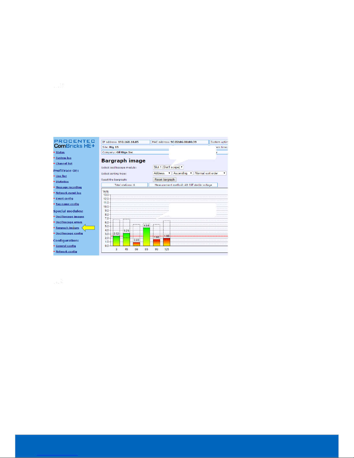
ComBricks HE+ User Manual | June 2017 | © PROCENTEC 59/104
You can view the Scope Error images per slot. The Head Station can hold 16 error images per slot in memory,
and if there are more than 16 error images you can click ‘Refresh error images’ to load these.
To clear all error messages from memory click ‘Reset scope error images’.
Bar graph
The Bar graph illustrates the average signal strength from all available connected devices behind a specific
SCOPE repeater. It is a helpful utility to get an impression of the overall signal quality of the network.
The average amplitude should be around 5 V. When there are bus problems the Bar graph will display different
Voltage levels and the color of the bars will change.
Streaming with ProfiTrace 2
Streaming with ProfiTrace 2 is a feature that allows the user to use the ProfiTrace 2 software and create a
scenario as if a ProfiCore is connected to the PC. ProfiTrace 2 is a software tool used by thousands of engineers
worldwide, so there is much experience with this tool. A license for ProfiTrace 2 is not required.
Streaming with ProfiTrace 2 only works under the following circumstances and settings:
• Only Head Stations with a type 1B or 1C license
• Max. 1.5 Mbps (PROFIBUS)
• Clean TCP/IP connection
• ProfiTrace 2.6.0 or higher
• Only 1 ComBricks connection
After successfully installing ProfiTrace 2, you can find a 'ProfiTrace v2.x for ComBricks' in the start menu of
Windows (see Fig. 45).
Fig. 44 - Bar graph
Selected module
Signal quality
Page 60

ComBricks HE+ User Manual | June 2017 | © PROCENTEC 60/104
This is the standard ProfiTrace2.exe, but with an additional parameter; ProfiTrace2.exe" -_CBMODE_
After Starting 'ProfiTrace V2.x for ComBricks' ProfiTrace will initially look very similar to the regular version, but
now with a reduced number of program option tabs offered near top of screen. The ScopeWare, Bargraph,
Topology, ProfiCaptain and other tabs/menus are missing to the right of the single ProfiTrace tab (see Fig. 45).
2.Connect to a
COMbricks unit
1. Start this
shortcut from the
Start Menu
Fig. 45 - Starting ProfiTrace 2 for ComBricks
Page 61

ComBricks HE+ User Manual | June 2017 | © PROCENTEC 61/104
After clicking on the 'Connect ComBricks' button, a mid-screen dialogue window is displayed which is used to
setup the connection with ComBricks HE+ (see Fig. 46).
Important parameters for the connection and the streaming process:
• IP number
• User type and password
• Network number
If one of the connection parameters is incorrect, the connection will
not be established or no data is streamed. It is recommended
to start the discovery tool to verify the IP connection.
Multiple connection instances can be saved and loaded each with their own connection parameters.
ComBricks HE+ itself can handle 1 streaming connection, but on the PC
multiple ProfiTrace instances can be opened that simultaneously
communicate with different ComBricks units.
Summary of Statistics and Events
This paragraph contains a description of the items listed in the statistics and/or events.
Available
connections
Start connection
Start discovery tool
Important parameters!
(network, user and
password)
Fig. 46 - Setting up the connection
Page 62

ComBricks HE+ User Manual | June 2017 | © PROCENTEC 62/104
Statistic
Description
Critical
Lost
How many times a device in data exchange fails to respond after
the maximum retries have been reached. Lost is retriggered
when the device recovers back to data exchange and fails to
respond again.
- Live List will indicate a yellow colored address (after time-out).
- When the device was already lost after the activation of
ProfiTrace Lost will not be updated. Only Syncs will indicate the
problem.
YES
Syncs
Attempts of the master to contact a device for the first time or
establish a communication relationship. This occurs in most cases
after station lost, device unavailability or startup of the master.
In the statistics view this values adds up relatively quick.
- Some DCS systems read diagnostics all the time with Syncs ON.
- Live List could indicate a yellow colored address.
YES
(in most
cases)
Repeats Total
Attempt of the master to get a response from an unanswered
telegram. The response did not come or has content errors. The
maximum amount of repeats a master attempts can be
customized in the master.
When the retries have reached the limit, the master goes to the
Syncs state
YES
Repeats Max
(worst sequence)
This value represents the highest amount of retries that were
attempted on this specific device in one cycle.
- This value will never get higher than the retry value that has
been setup in the master.
YES
Illegal Responses
The response to a master request telegram contains framing
errors (parity error, wrong FCS, SD error, etc). This mostly
happens with EMC and cabling problems.
- When this statistic adds up relatively quick, it could also be a
double device address.
YES
Int. diag (RS & RR)
Unexpected response message from a slave. This can happen
when a slave does not understand a master message (Reject
Service) or when the slave is not ready for an answer yet (Reject
Resource).
NO
Ext. diag
The number of times a slave has correctly answered a Get
Diagnostics message back to the master.
NO
Page 63

ComBricks HE+ User Manual | June 2017 | © PROCENTEC 63/104
Statistic
Description
Critical
Ext. diag while in DX
The number of times a slave has correctly answered a Get
Diagnostics message back to the master when it was already in
Data Exchange. This statistic can be used to determine the count
of diagnostic signals from slave to master during normal
operation.
NO
Network event
Description
Master lost
Baudrate change
ComBricks locks to a new baudrate
Low/High signal
(bargraph)
The bargraph signal (customizable in the scope settings) has been
too low or too high. A high bargraph is not good in PA networks.
Redundancy fail
One of the redundant cables has a problem
PA/FF Events
The DC values of a PA or FF are out of range
Low/High signal
(fiber optic)
The fiber optical budget is too low.
Page 64

ComBricks HE+ User Manual | June 2017 | © PROCENTEC 64/104
6. Head Station
The Head Station is the primary element of ComBricks HE+. It schedules the interaction
between all modules and provides data storage and an Ethernet interface for the user.
Overview
All ComBricks HE+ Head Stations feature a ProfiTrace core and advanced web server for
permanent remote maintenance of the PROFIBUS installation over Ethernet.
• Type 1B: Monitors 1 PROFIBUS network + ProfiTrace 2 streaming + OPC
• Type 1C: Monitors 4 PROFIBUS networks + ProfiTrace 2 streaming + OPC
For the monitoring with ProfiTrace OE, repeater modules or slave modules are required to provide PROFIBUS
telegrams on the backplane network.
Head Stations are able to stream live data directly in the ProfiTrace 2 software package over Ethernet.
ProfiTrace 2 will run with full busmonitoring functionality and the user can benefit from its features.
The Head Station provides power to all modules through its redundant power supply. If the power is
insufficient, an additional Power Module can be added to the ComBricks set to supply more power (this
module is not available yet in the HE+ version).
Table 2 - Head Station comparison
Head Station HE+ 1C
(101-30011C)
Head Station HE+ 1B
(101-30011B)
Selectable networks
(for repeater modules)
4
4
Web server
YES
YES
CommDTM / Class 2 master
YES
YES
SNMP
YES
YES
ProfiTrace OE networks
(for monitoring)
4
1
Oscilloscope features
YES
YES
ProfiTrace 2 live streaming
YES
YES
OPC
YES
YES
Page 65

ComBricks HE+ User Manual | June 2017 | © PROCENTEC 65/104
Relay contact
With the relay contact (marked ‘RL’) it is possible to react on an event
(retries, lost, bus voltage too low, etc). It is also possible to control the relay
manual or on a timer. Refer to paragraph 5.4 for details. The relay is capable
of switching 0.4 A - 24 V.
SD card
The SD card is used to store ProfiTrace file recording data, logs, the GSD info
file and backup settings.
By default a 1 GB SD card is supplied together with the Head Station, but it
can be exchanged by an SD card with a maximum size of 32 GB.
The SD card is addressable directly with an FTP client. In the FTP software the
SD card has a drive letter with a directory structure, on which files can be
read and written from and to the SD card. When the password is set in the
web server, this same password has to be used by the FTP software to
establish a connection.
6.3.1 Inserting/replacing the SD card
The socket is located on the front plate of the Head Station.
To remove the SD card, gently press it inwards. The SD card is unlocked and released from the socket.
With insertion, just insert the SD card in the socket and press it inwards. The SD card socket has a polarity to
make sure it is not inserted backwards.
The SD card is hot swappable, but there is a risk that
monitoring data is lost when the system wants to write
at exactly the same time as the removal or insertion.
6.3.2 Life cycle of the SD card
The life of a SD card depends on the following factors:
- Number of read and write operations
- Ambient temperature
At an ambient temperature of -20 °C to 60 °C the SD card has a service life of 10-years at maximum 100000
write/delete sequences.
If the maximum number of read and write operations has exceeded the limits, data loss may be possible.
6.3.3 Directories and files
The following directories have been standardized for ComBricks and are in most cases located on the SD card;
Switchable relay
Removable SD card
Page 66

ComBricks HE+ User Manual | June 2017 | © PROCENTEC 66/104
Directories
Description
/Busmon
ProfiTrace message recording files
(Head Station type 1B and 1C only)
/Log
Log files
/Doc
Contains the web server download page
(See paragraph 4.10 on how to set it up)
Files and extensions
Description
Journal.DAT
System file
(Do not delete or remove it)
GSD.BIN
File with GSD information for the Live List.
(Generated with the ProfiTrace 2 software).
See paragraph 5.1.1 how to generate this file.
SETTINGS.INI
Head Station settings
(IP address, name, location, etc.)
LICxxxxxxx.TXT
License files
.PTC
ProfiTrace OE message recoding files. (located in the "Busmon" directory).
The files can be opened with ProfiTrace V2.5.3 and higher (See paragraph
5.3 on how to generate PTC files).
.PKG
Firmware files
.CSV
Log files
(located in the "Log" directory)
Page 67

ComBricks HE+ User Manual | June 2017 | © PROCENTEC 67/104
Normal
menu
(NL)
Special
Menu
(SL)
Wait
key
(L1)
Read settings
from SD card
Tap Down
Hold
up for
5 seconds
Hold up
For 5 seconds
Wait
key
(L2)
Save settings
to SD card
Tap Down/Up
Hold
up for
5 seconds
Wait
key
(L3)
Clear
password
Tap Down/Up
Hold
up for
5 seconds
Wait
key
(L4)
Reset to
factory
defaults
Tap Down/Up
Hold
up for
5 seconds
Wait
key
(L5)
Warm start
Tap Down/Up
Hold
up for
5 seconds
Tap Down/Up
Execution
confirmed
(XC)
Done
Done
Done
Done
Done
Done
Timeout,
or held down
for 5 seconds
Switch navigation of the Head Station
Description
NL
SL
Normal mode
(starting point)
All LEDs Blinking
L1
RDY Blinking
L2
ETH Blinking
L3
SF Blinking
L4
IOF Blinking
L5
USB Blinking
XC
LED walk through all
the LEDs
Start
Page 68

ComBricks HE+ User Manual | June 2017 | © PROCENTEC 68/104
LEDs on the Head Station
In the tables below the LEDs of the Head Stations during normal operation are described. The LED conditions in
firmware update and menu mode are not described here.
RDY - Ready
OFF
Blinking
ON
Starting up X
Run
X
ETH - Ethernet
OFF
Blinking
ON
No Ethernet link established
X
DHCP configuration is pending
X
Ethernet link established
X
SF - System failure on the Head Station
OFF
Blinking
ON
OK X
Backplane voltage too low (under 5,5 VDC) or current
draw to high (above 2,5 A)
Fast
Clock-chip error
(contact your local Distributor or PROCENTEC)
Slow
Internal component or firmware error
(contact your local Distributor or PROCENTEC)
X
Page 69

ComBricks HE+ User Manual | June 2017 | © PROCENTEC 69/104
7. Scope Repeater Modules (RS485)
Different than the modules of the standard ComBricks, the HE+ system has two repeater
slots in one physical module. These are equipped with screw terminals, additional DB9
connector, onboard termination, diagnostic LEDs and redundancy feature.
The advanced 12 Mbps core of the repeater module is identical as the ProfiHub and
repeater B1; it can be cascaded unlimitedly and has increased RS 485 strength. It does not
have the frustrating short-circuit bug and the bus communication is constantly monitored
for glitches which are digitally filtered out. Every channel has on-board switchable
termination and is able to drive 31 devices.
The repeater channels are directly connected with the ProfiTrace OE core in the 1B/1C Head
Station. Busmonitor data is directly available in the web server.
4 Repeater slots (two physical modules) can be inserted in the backplane.
Two slots in one module
The Scope Module with order code 101-301220 has two galvanically isolated channels. It uses two slots in the
backplane of the ComBricks, but it is one physical module. Each channel can be assigned to a specific backplane
network by means of the NW dipswitches or the web server.
The channels have 1 screw terminal and a termination switch. In most cases, the channel starts here so the
termination must be set to ‘ON’. If the channel is not the beginning, use the DB9 connector, see paragraph 3.9.
Alternatively, use the dual ground clip to install two cables in one screw terminal, see Fig. 47.
Fig. 47 - Channel structure of the 2 channel scope module
ProfiTrace OE is able to monitor 4 PROFIBUS networks with 2 units of 2 channel repeater modules.
The DB9 connector is connected 1-on-1 to the connectors of the respective channels.
Page 70

ComBricks HE+ User Manual | June 2017 | © PROCENTEC 70/104
Channel structure
Every Channel is electrically isolated and internally connected to one of the transparent PROFIBUS networks on
the backplane (see Fig. 48).
The shielding of the PROFIBUS cable can be directly grounded or indirectly grounded (see paragraph 7.4).
The termination is switchable and powered by the repeater module. A green LED on the front of the module or
in the web server diagnostics indicate the status of the termination switch.
Fig. 48 - Channel structure of one repeater
Page 71

ComBricks HE+ User Manual | June 2017 | © PROCENTEC 71/104
EMC barrier
The galvanic isolation and bit recovery circuit in the repeater modules, make the ComBricks perfect to act as an
EMC barrier for sensitive areas.
Grounding system
There are 3 methods to ground the PROFIBUS cable:
1) Direct grounding
2) Indirect grounding (through a capacitor)
3) Combination of direct and indirect.
In most cases it is recommended always to use Direct Grounding with the power supply and the shielding of
the PROFIBUS cables. If you do not want to ground all or some cables to the common ground, the cable
shielding should be connected to pin ‘I’. A capacitor with a parallel high value resistor will separate the 2
potentials (see Fig. 48).
If by accident on 1 channel the Direct Grounding is connected with the Indirect Grounding, the connection to
the Direct Grounding bypasses the capacitor in the Indirect Ground connection. The current on the shield will
flow to Direct Ground.
Baudrate detection
It takes less than 10 seconds for a module to detect the baudrate (in practice it will be around 3 seconds). The
detection mechanism is started when telegrams enter the module from the field side (not the backplane). If
the baudrate has been detected, the 'ER' LED will be OFF.
When the baudrate has been detected, the module has to "see" a valid telegram within 50 seconds, otherwise
the module unlocks the baudrate and the 'ER' LED will be ON.
Fig. 49 - ComBricks as EMC barrier
Page 72

ComBricks HE+ User Manual | June 2017 | © PROCENTEC 72/104
PROFIBUS DP cable lengths
The length of the PROFIBUS cable connected to the repeater channels should comply with the PROFIBUS DP
cable specifications for RS 485.
PROFIBUS DP cable specifications
The cable should comply with the PROFIBUS DP cable specifications for RS 485.
Table 3 - PROFIBUS DP cable specifications
Parameter
Value
Parameter
Value
Wires
2 (twisted)
Wire diameter
≥ 0.64 mm
Impedance
150 Ohm (3 to 20 MHz)
Wire area
≥ 0.32 mm2
Capacity
≤ 30 pF/m
Shielding resistance
≤ 9.5 Ohm/km
Loop resistance
≤ 110 Ohm/km
Fig. 50 - PROFIBUS DP calbe lengths
Page 73

ComBricks HE+ User Manual | June 2017 | © PROCENTEC 73/104
PROFIBUS DP cable types
The repeater modules can handle PROFIBUS cable based on multiple protection sheaths with a diameter
between 6 to 12 mm (when the grounding clip is used).
• Robust cable
• Food cable
• Ground cable
• Trailing cable
• Festoon cable
• Fire and heat cable
• Flexible cable
• Shipboard cable
• Rodent protection cable
FRNC cable
Shipboard cable
Festoon cable
Flexible cable
Food cable
Robust cable
Trailing cable
Hybrid cable
Fig. 51 – Range of supported PROFIBUS cable types
Page 74

ComBricks HE+ User Manual | June 2017 | © PROCENTEC 74/104
Redundancy
The bus redundancy technology of the repeater modules is very advanced. A redundant system can be built
using 10 parallel cables. This architecture provides extremely high availability. It is compatible with the RLM01
from ABB.
The redundancy procedure is as follows:
All the repeater channels of the specific application have to be assigned to the same network group. The
repeater channels that carry the redundant task have to be activated with the RED switch. After a reset or
power-up the redundancy system works directly.
ComBricks locks itself to the first redundant channel that has a valid start delimiter.
If this channel does not have valid telegrams anymore, ComBricks locks itself to the next redundant channel
with a valid start delimiter. There is no logic which redundant channel is selected.
Fig. 52 illustrates an application with 3 redundant segments. 3 Repeater modules of each ComBricks are set
with the RED switch set to ON and are wired to the redundant segments.
The devices and the controller(s) are connected to the regular repeater modules. The maximum amount of
devices which is allowed behind a regular repeater module depends on the application (between 1 and 31
devices).
Mixing with other repeaters
Normally it is advised not to mix regular repeaters because of the limitation in cascading that these repeaters
have (caused by the bit width alteration due to internal opto-couplers and digital electronics).
ComBricks regenerates the telegrams (same as a ProfiHub or B1 Repeater). This means there is just a small
delay time, but no limitations in cascading.
If you mix ComBricks with other repeaters you only have to follow the cascading rules of the other repeater
manufacturer. If the other repeaters are also from PROCENTEC, you can cascade and mix without problems.
Keep in mind that monitoring will fully work, but the SCOPE repeaters only measure the signals up to the first
repeater module.
Fig. 52 - Application with 3 redundant segments
Page 75

ComBricks HE+ User Manual | June 2017 | © PROCENTEC 75/104
LEDs of the repeater module
The LEDs on the repeater modules are very useful for visual diagnostics.
Table 4 - LEDs on the standard repeater module
OFF
Blinking
ON
RDY
Repeater module has
NOT been configured yet.
Head Station is configuring
the repeater module.
Repeater module has
been configured and is
operational
RX
NO valid telegrams
detected on this channel.
1 or more devices are
communicating on this channel.
1 or more devices are
communicating on this
channel.
ER
The baudrate has been
detected.
Problem in the cabling has
been detected on this channel.
This channel has not
detected the baudrate (yet) or
there is a problem with the
wiring of the cable.
SW
Internal termination for this
channel is OFF.
Internal termination for this
channel has been activated.
Fig. 53 - Example of mixed repeater network
5 6 710 11
40 41
1.5 Mbps
3 4
200 m 200 m
Page 76

ComBricks HE+ User Manual | June 2017 | © PROCENTEC 76/104
OFF
Blinking
ON
ML
Valid telegram
signal amplitude (> 2.5
V)
Telegram signal
amplitude is too low
(< 2.5 V)
TL
Valid idle voltage
(~ 1 V).
Idle voltage is too
low (< 1 V)
HW
Repeater is
operational.
Internal repeater
error (contact
PROCENTEC)
Page 77

ComBricks HE+ User Manual | June 2017 | © PROCENTEC 77/104
8. CommDTM
The ComBricks Head Station features a fully functional gateway between any Windows platform and field
devices using a CommDTM. This enables the ComBricks to function as a real Asset Management tool. Currently
we support FDT 1.2 frame applications such as PACTware and E+H FieldCare. During interaction with the
CommDTM, all ComBricks functions can be used simultaneously (web based monitoring, oscilloscoping, OPC
and alarms via email).
If you are using Siemens EDD files, you can convert these to DTM files using a tool called Sitrans DTM. More
information can be found on www.siemens.com/sitransdtm.
Installing drivers, CommDTM and server
You can download the required PCD server and CommDTM installers separately from our website, located at
the download section. You can also find the files in the Download page of the ComBricks itself.
It is a ZIP file containing several executables, which should all be installed.
Setting up the PCD server
Start the PCD (PROCENTEC Communication Driver) server (located in /Program Files/PROCENTEC/PCD/). You
should see the PCD logo in the system tray.
Page 78

ComBricks HE+ User Manual | June 2017 | © PROCENTEC 78/104
Right-click the PCD icon, then choose ‘Show’. Click ‘Modify’, enter a name for the interface, choose the latest
‘ComBricks PROFIBUS x.x’ driver and click ‘OK’. Note: You can leave the serial number field empty.
Fig. 54 - Setting up the PCD server
Next, select this location again and click ‘Setup’. Enter the correct IP address of the ComBricks Head Station,
and choose the port and network you wish to connect to. Depending on the password settings in the
ComBricks, you might also have to fill in a username and password. Then click ‘Ok’.
Using the CommDTM
Start your FDT manager and create or load a project. Vendor-independent platform PACTware is used in the
example below. Refer to the manual of your FDT manager for details.
Page 79

ComBricks HE+ User Manual | June 2017 | © PROCENTEC 79/104
In the upper menu, choose ‘Device – Add device’ and click on ‘PROCENTEC DP-V1 Master’, as shown in
Fig. 55.
Fig. 55 - CommDTM selection dialog
After clicking ‘OK’ the PCD server is launched automatically (if it was not loaded already). You will see the
ComBricks and PCD icons appear in the system tray:
Select PROCENTEC and
choose the DP-V1 Master
Select PROCENTEC and
choose the DP-V1 Master
Page 80

ComBricks HE+ User Manual | June 2017 | © PROCENTEC 80/104
In PACTware, make sure to set the correct bus parameters by right-clicking the PROCENTEC DP-V1 master and
choose ‘Parameters’. Enter the correct parameters or select ‘Start’ to auto-detect these (see Fig. 56). Then
click ‘OK’. Next, choose the icon ‘Connect’ from the top menu.
Fig. 56 - DTM master parameters
Please note: not all busparameters will be detected automatically; You can set them manually:
• Max. retry limit: recommended is a value of 3 or higher.
• Target Rotation Time: This is a calculated worst-case time for one token rotation on the PROFIBUS network.
Look up this value in the primary master setup tool, and copy it here.
• Max Station delay: this value is defined by the slowest slave in the network. In most cases the default value
is sufficient.
• Quiet time: only required in case of heavy reflections.
After you have correctly applied these steps, the ComBricks is now a DP-V1 master and ready for
communication to field devices. For a detailed walk-through refer to the Download section of the PROCENTEC
website for a comprehensive Quick Start for PACTware and FieldCare.
Page 81

ComBricks HE+ User Manual | June 2017 | © PROCENTEC 81/104
9. OPC
OPC functionality in ComBricks is available in the following way: By opening a stream from the ComBricks
Headstation to a PC in the local network, all PROFIBUS messages are sent to this computer. This PC has
ProfiTrace running, and in ProfiTrace the OPC server is active. So the actual OPC server is inside ProfiTrace, not
in the Headstation. OPC tags can be added in the ProfiTrace OPC server, which can be read by OPC clients.
The ProfiTrace OPC Server offers a standardized interface to get the valuable ProfiTrace information such as
device status, statistics and process variables into applications that carry an OPC client, such as SCADA, Excel,
etc.
Many process or factory plants nowadays use SCADA or Asset management software to get an overview of the
production status and application alarms. However, they have no insight on the PROFIBUS health and
behaviour which could indicate a potential shutdown. This information contributes heavily to the installation
uptime.
Using ProfiTrace OPC, it is possible to get the real live state of your PROFIBUS network directly in your SCADA
system, allowing maintenance engineers and operators to react quickly to any PROFIBUS related alarms or
irregular events coming up on the screen. The opportunities are vast and we are just discovering the
possibilities what it could contribute to your asset management.
You can display ProfiTrace tags in a SCADA/HMI package or link it to an SMS/email client and sent a message
when something happens with the PROFIBUS installation or even generate your own report in MS Word/Excel.
Every application that acts as OPC client can approach the ProfiTrace tags. It does NOT corrupt the PROFIBUS
cycle time because the information comes from busmonitoring (listening).
Installing the OPC drivers
The PC that runs ProfiTrace has to be prepared for OPC by installing the drivers (see Fig. 57).
Page 82

ComBricks HE+ User Manual | June 2017 | © PROCENTEC 82/104
Selecting OPC tags
The OPC tag settings can be found in the Settings menu (see Fig. 58).
You caninstall the drivers
directlyfrom the file folders…..
….. or the ProfiTrace folder in
the Start menu (easier!)
1) It takes a relatively
long time to install
the drivers!
Fig. 57 - Location of the OPC drivers
Select Setup OPC Tag Settings
Fig. 58 - OPC tags in the Settings menu
Page 83

ComBricks HE+ User Manual | June 2017 | © PROCENTEC 83/104
In the next dialog you can add tags (see Fig. 59). All basic tags are already available (Live List, and Statistics).
When you do not require additional tags, you do not have to enter this dialog and can you directly proceed to
the server settings.
The OPC tags are locations in the I/O data of the devices (offset 0 is the first location).
Be careful with too many tags. The quantity of tags can slow down your system, especially when
you want to run multiple applications at the same time. To solve this you can filter tags in the client
you are using.
You can save your data in a .PTO file which is used later during the setup of the OPC server.
Tags which are already available
(Live List, Statistics, etc.)
Adding a variable tag
pointingto slave data
Save TagData when ready
(alsoduring operation)
Confirm the
settings
Fig. 59 - Adding OPC tags
Page 84

ComBricks HE+ User Manual | June 2017 | © PROCENTEC 84/104
Activating the OPC server
After setting up the OPC tags, the server has to be activated.
The OPC server settings can be found in the Settings menu (see Fig. 60).
In the next dialog the server can be added (see Fig. 61).
A maximum of 16 servers can be created, each with its own tag groups.
Select Setup OPC Server
Fig. 60 - OPC server in the Settings menu
Page 85

ComBricks HE+ User Manual | June 2017 | © PROCENTEC 85/104
Important: If you see an error message when adding/registering the server or tags, then restart the software
and start ProfiTrace with 'Administrator rights by right-clicking the ProfiTrace executable and choosing 'Run
as administrator'.
In the next dialog the properties of the server are set up (see Fig. 62).
Give it an appropriate name and indicate if you want to use the default tags or the .PTO file with the user
defined tags. Also choose a ComBricks connection.
When the settings are completed click “close” and the OPC server will be active. In later stages the OPC server
settings can be modified.
From this point any application that has the availability of an OPC client can access the ProfiTrace OPC tags.
Add a newOPC server
Fig. 61 - Adding the OPC server
Fig. 62 - OPC server properties
4. Confirm the
settings
2. Use an existing
ComBricks
connection
3. File name with tags or
just use the default tags
1. Assign a name or
keep the default name
Ready!
Optional; check this
to run ProfiTrace in
system tray only
Page 86

ComBricks HE+ User Manual | June 2017 | © PROCENTEC 86/104
10. SNMP
The Headstation has a powerful feature, SNMP, available free of charge in every Headstation version.
With SNMP you can retrieve any data via Ethernet that has been collected by the ComBricks system. This SNMP
data can be used by network management tools or SCADA systems to visualize the collected data.
This data ranges from Bargraph data (voltages) to statistics and Live List information. You can also retrieve the
Headstation temperature or power consumption for example. This turns a SCADA system into a versatile
monitoring or alarming station.
The SNMP MIB (Management Information Base) file, which is available for download on our website, contains
the descriptions for all items. This MIB file should be used in a management tool or MIB viewer to retrieve the
data from ComBricks.
List of data items
The following items can be retrieved with SNMPv1 from the ComBricks:
General items
• Serial number of the Headstation
• Firmware version of the Headstation
• Hardware version of the Headstation
• Backplane version
• FPGA version of the Headstation
• General description of the Headstation
Ethernet status
• MAC address
• IP address
• Subnet mask
• Default gateway
• DNS address
• DHCP state
Device
• System time
• System temperature
• System current
• System voltage
• System status
• System I/O status
• Micro SD card status
• License code
• Number of modules
• Module info
Page 87

ComBricks HE+ User Manual | June 2017 | © PROCENTEC 87/104
Data
• Livelist of all 4 networks
• Statistics of all 4 networks (Lost, Syncs, Repeats total, Repeats Max, illegals, Int diag, Ext diag, DX diag)
• Ident numbers of active devices, of all 4 networks
• Detected baudrate of all 4 networks
• Connected Ethernet clients
• Connected ports
• Physical measurements per slave:
• Min
• Max
• Last
• Idle voltage per slave
• Bargraph settings
Viewing the MIB file
As an example the tool SNMPb will be used. This tool can be downloaded for free.
Prepare the SNMPb tool as follows:
1. Download and install SNMPb
2. Download the MIB file and place it in C:\Program files (x86)\Snmpb\mibs\
3. Start SNMPb and click the tab ‘Modules’. Search for the module ‘PROCENTEC-COMBRICKS-HS-T1-MIB’,
select it and click the button -> so that the module moves to the right table. It is now loaded.
4. Go back to the tab ‘Tree’ and click the setup button .
5. Enter a name for the profile and enter the IP address of the target ComBricks. Use default SNMP port 161
and other default settings. Then click OK.
Now you can expand the items in the MIB tree by right-clicking on ‘MIB Tree’ and select ‘Expand’. The first
SNMP item you see is ‘hsGenSerial’ in the ‘General’ folder. To read this value, right-click and choose ‘Get’. The
Enter a name
Enter the ComBricks
IP address
Page 88

ComBricks HE+ User Manual | June 2017 | © PROCENTEC 88/104
program will now send an SNMP message to the ComBricks and the ComBricks will send the requested
information back, which will now be visible in blue text.
You can also retrieve all information in the selected folder. Right-click a folder and choose ‘Walk’. All
information of items in the selected folder or entry will now be retrieved.
Fig. 63 - Example of reading SNMP data
The info panel of SNMPb shows the description and details of the selected SNMP item.
For other freeware SNMP tools, see paragraph 12.5.
Item description from
the MIB file
Click ‘Walk’ to read all SNMP
data items in this folder.
Results of the ‘Walk’
in blue
Page 89

ComBricks HE+ User Manual | June 2017 | © PROCENTEC 89/104
11. Firmware updates
The Updater tool and new firmware for the Head Station and for the modules can be downloaded from
www.procentec.com.
Firmware files have the extension .PKG.
For updating the firmware of the Head Station a mini USB cable is required.
For updating modules an Ethernet connection to the ComBricks is required.
Updating the Head Station
The Firmware Update procedure requires a power-down of the ComBricks system. Modules will not
be active during the update sequence. This means that the repeater functionality of the ComBricks
is disabled and (parts of) the network will be down.
After downloading the firmware and installing the firmware update tool, follow the procedure below:
STEP 1: Shutdown ALL power to the Head Station (also USB cables and power modules).
STEP 2: Hold the menu switch of the Head Station down and at the same time provide power to
the Head Station. In the firmware update mode the SF and IOF LEDs should be blinking.
STEP 3: Connect the mini USB to the Head Station (see Fout! Verwijzingsbron niet gevonden.).
STEP 4: Start the firmware update tool. If the tool detects the Head Station in the firmware update
mode, the "Start update" button is enabled (see Fout! Verwijzingsbron niet gevonden.).
STEP 5: Click on "Start update" to browse to the .PKG file and click "OK". The tool will now upload the
new firmware to the Head Station
STEP 6: After the upload the Head Station will update the firmware. This can take a few minutes. The
window that appears be can closed directly.
STEP 7: Verify the firmware update by checking the firmware version in the web server (bottom of
each web page).
Page 90

ComBricks HE+ User Manual | June 2017 | © PROCENTEC 90/104
Updating modules
Some ComBricks modules can get new functionality by updating the module firmware. These updates are not
distributed through the Head Station firmware, but in separate Module firmware packages. For a listing of all
available firmware, see www.procentec.com.
The tool for updating the module firmware is different than the tool for updating the Head Station. It can be
downloaded from the above mentioned location.
After downloading the update tool and the module firmware follow the procedure below:
Fig. 65 - Updating module
Fig. 64 - Update complete
STEP 1: Make sure the Head Station and targeted module(s) are powered and running.
STEP 2: Connect an Ethernet cable between the Head Station and your workstation and verify the
network connection.
STEP 3: Start the Module firmware update tool and enter the IP address of the targeted ComBricks
Head Station. If you do not know the IP address, use ‘Search network’ to open the Discovery
Tool and select the correct Head Station.
STEP 4: Click ‘Connect to Head station’ in the Update tool. It will scan all slots to check the module
types.
STEP 5: Double-click the targeted module slot. A file dialog will appear; navigate to the local folder
where you stored the firmware package.
STEP 6: The tool automatically filters all unrelated firmware files; you cannot select incorrect files.
Choose the firmware and click ‘Open’. The firmware update will start automatically. You
should see the windows as shown in Fig. 65 and Fig. 64.
Double-click a
module to select a
firmware file
Use the Discovery Tool if you
do not know the IP address
Page 91

ComBricks HE+ User Manual | June 2017 | © PROCENTEC 91/104
12. Tips and tricks
Ident number lookup
It is possible to check if ComBricks has info on a certain Ident Number (located in gsd.bin):
[ComBricks IP or DNS address]/data_srv.cgi?data=gsdinfo:0x[Ident Number]
Example: http://192.168.1.230/data_srv.cgi?data=gsdinfo:0x6012
It should display a line comparable with this:
ABB%20Drives%20NPBA%2D12%1FABB%2DDRIVES%1F40%1F8%1FNPBA%2D12%.....
Solution for secured email connections
Because ComBricks can only handle unsecured email connections, a proxy between ComBricks email and
outgoing email could be helpful. hMailserver is a free tool that creates a mail server on one of the local PCs in
the network. ComBricks can mail the events to this mailserver and the mailserver can forward it through a
secured connection to an external mailserver.
www.hmailserver.com
IP address adjustment tool
Every time you go 1-on-1 with a laptop to a ComBricks unit, the IP settings of your laptop have to be adjusted
to fit the local IP address of the ComBricks. To make this step very easy a tool is available with the name
NetSetMan to automatically change all the settings according to customized profiles.
www.netsetman.com
Free WiFi channel detector
For ComBricks streaming with the ProfiTrace 2 software over Wi-Fi, a clean connection is required to keep the
streaming performance as high as possible. To verify that your Wi-Fi does not overlap with other channels, we
recommend to use the free tool inSSIDer.
www.metageek.net/products/inssider
Some SNMP tools
To test the ComBricks SNMP functionality, you can use the tools below:
• SNMPb
• NetSentinel by Micromedia
• MIBbrowser by iReasoning
• Solarwinds
Page 92

ComBricks HE+ User Manual | June 2017 | © PROCENTEC 92/104
13. Sales offices and distributors
HEADQUARTERS
PROCENTEC T: +31 (0)174 671 800
Klopperman 16 F: +31 (0)174 671 801
2292 JD WATERINGEN E: info@procentec.com
Netherlands W: www.procentec.com
ARGENTINA
eFALCOM T: +54 237 46 31 151
Alcorta 2411 F: +54 237 46 31 150
B1744 - Moreno E: santiago.falcomer@efalcom.com
Buenos Aires W: www.efalcom.com
Argentina
AUSTRIA
RELISTE T: +43 2236 315 25-25
Enzersdorfer Straße 8-10 F: +43 2236 315 25-60
A-2345 Brunn am Gebirge E: office@reliste.at
Austria W: www.relise.at
AUSTRALIA
IS Systems Pty Limited T: +61 2 4964 8548
14 Laverick Ave., F: +61 2 4964 8877
Tomago E: fritz.woller@issystems.com.au
NSW, Australia, 2322 W: www.issystems.com.au
Pentair Flow Control Pacific T: +61 2 4448 0466
1 Percival Road F: +61 2 4423 3232
Smithfield E: sharee.hazell@pentair.com.au
NSW, Australia, 2164 W: www.profibuscentre.com.au
BELGIUM and LUXEMBOURG
Bintz Technics N.V. T: +32 2 720 49 16
Brixtonlaan 23 F: +32 2 720 37 50
B-1930 Zaventem E: bloemen@bintz.be
Belgium W: www.bintz.be
BRAZIL
Westcon Instrument. Indl Ltda T: +55 11 5561-7488
Rual Alvaro Rodrigues, 257 F: +55 11 5093-2592
São Paulo – SP E: paolo@wii.com.br
Brazil - CEP 04582-000 W: www.wii.com.br
CANADA
Streamline Process Management Inc. T: +1 403 225 1986
#3, 4351 – 104 Ave SE F: +1 587 585 2828
Calgary, Alberta T2C 5C6 E: admin@streamlinepm.com
Canada W: www.streamlinepm.com
CHILE
RP Ingenieria Limitada T: +56 41 246 93 50
Tucapel 92 oficina 52 F: +56 41 252 25 92
Concepción E: rodrigopinto@rpingenieria.cl
Chile W: www.rpingenieria.cl
CHINA
PROCENTEC Beijing T: +86 (10)847 669 11 / +86 (10) 847 873 11
Room E-1115 WangJingYuan YouLeHui F: +86 (10)847 667 22
ChaoYang E: info@procentec.net
Beijing W: www.procentec.net
China
CZECH REPUBLIC
FOXON s.r.o. T: +420 484 845 555
Polní 367 F: +420 484 845 556
460 01 Liberec 12 E: foxon@foxon.cz
Czech Republic W: www.foxon.cz
Page 93

ComBricks HE+ User Manual | June 2017 | © PROCENTEC 93/104
DENMARK
ProSaiCon T: +45 70 20 52 01
Jernbanegade 23B F: +45 70 20 52 02
DK 4000 Roskilde E: hfj@prosaicon.dk
Denmark W: www.prosaicon.dk
EGYPT
Mas Trading T: +2 02 2524 2842
37, 105 Street F: +2 02 2524 2843
Al-Etihad Square E: aya.elshafei@masautomation.com
Egypt W: www.masautomation.com
ESTONIA
Saksa Automaatika OU T: +372 605 2526
Peterburi Tee 49 F: +372 605 2524
Tailinn E: info@saksa-automaatika.ee
EE-11415 Estonia W: www.saksa-automaatika.ee
FINLAND
Hantekno Oy T: +358 40 8222 014
Kalliotie 2 E: info@hantekno.com
04360 Tuusula W: www.hantekno.fi
Finland
FRANCE
AGILiCOM T: +33 247 76 10 20
Bâtiment B F: +33 247 37 95 54
1, rue de la Briaudière E: jy.bois@agilicom.fr
Z.A. La Châtaigneraie W: www.agilicom.fr
37510 BALLAN-MIRE
France
GERMANY
PROCENTEC GmbH T: +49 721 831 663-0
Benzstrasse 15 F: +49 721 831 663-29
D-76185 Karlsruhe E: info@procentec.de
Germany W: www.procentec.de
INDIA
UL Engineering Services & Software Pvt Ltd T: +91 202 696 0050
Nirman Classic, F: +91 202 696 2079
Katraj-Kondhwa Road, E: dileep.miskin@ulepl.com
Katraj, Pune-411046 W: www.ulepl.com
India
Automation Combine T: +98 452 84 550 / +98 452 030 47
B.R. House 4th Floor, F: +93 421 375 34 / +93 425 002 90
Hennur Main Road E: info@automationcombine.com
Bangalore 560043 W: www.automationcombine.in
India
IRELAND
PROFIBUS Ireland T: +353 61 202 107 or +353 61 240 240
Automation Research Centre F: +353 61 202 582
University of Limerick E: info@profibus.ie
National Technology Park, Plassey W: www.profibus.ie
Limerick
Ireland
ISRAEL
Instrumetrics Industrial Control T: +972 9 835 70 90
8 Hamlacha St. F: +972 9 835 06 19
New Industrial Zone E: info@instrumetrics-ic.co.il
Netanya, 42170 W: www.inst-ic.co.il
Israel
ITALY
PROCENTEC Italy T: +39 030 200 8610
Via Branze n. 43/45 F: +39 030 238 0059
25123 Brescia E: www.procentec.it
Italy W: www.procentec.it
Page 94

ComBricks HE+ User Manual | June 2017 | © PROCENTEC 94/104
JAPAN
TJ Group T: +81 3 6450 3739
C/O Japanese PROFIBUS Organisation F: +81 3 6450 3739
West World Building 4F E: info@profibus.jp
3-1-6 Higashi-Gotanda,
Shinagawa-ku,
Tokyo, 141-0022
Japan
KOREA
Hi-PRO Tech. Co., Ltd. T: +82 82 31 216 2640
#2802, U-Tower, 1029 F: +82 82 31 216 2644
Youngduk-dong, Giheung-gu E: chays@hiprotech.co.kr
Yongin-Si, Kyunggi-do, W: www.profibus.co.kr
446-908 Korea
LEBANON
Industrial Technologies S.A.L. (ITEC) T: +961 1 491161
Point Center, Boulevard Fouad Chehab F: +961 1 491162
Sin El Fil E: sales@iteclb.com
Beirut W: www.iteclb.com
Lebanon
MEXICO
Grid Connect Inc. T: +1 530 219 2565 (Spanish)
E: tomf@gridconnect.com
W: www.gridconnect.com
NETHERLANDS
PROCENTEC B.V. T: +31 (0)174 671 800
Klopperman 16 F: +31 (0)174 671 801
2292 JD Wateringen E: info@procentec.com
Netherlands W: www.procentec.com
NORWAY
Nortelco Automation AS T: +47 22 57 61 00
Johan Scharffenbergs vei 95 E: post@nortelcoautomation.no
N-0694 Oslo I: www.nortelcoautomation.no
Norway
PERU
ControlWare T: +51 163 737 35
Jr. Los Silicios 5409 F: +51 152 804 54
Los Olivos - L39 E: info@controlware.com.pe
Peru W: www.controlware.com.pe
POLAND
INTEX Sp. z o.o. T: +48 32 230 75 16
ul. Portowa 4 F: +48 32 230 75 17
44-102 Gliwice E: intex@intex.com.pl
Poland W: www.intex.com.pl
PORTUGAL
IndustrialSys T: +351 96 716 16 05
Rua Alexandre Herculano 25 E: info@industrialsys.pt
Mangualde, 3530-144 W: www.industrialsys.pt
Portugal
ROMANIA
S.C. SVT Electronics S.R.L. T: + 40 744 383 666
Brǎila 7 F: +40 365 809 305
540331 Tg-Mure E: sajgo.tibor@svt.ro
Romania W: www.svt.ro
SAUDI ARABIA
ASM Process Automation T: +966 2 691 27 41
Al-Zahra Dist. – Attas st. F: +966 2 682 89 43
cross section with helmy Kutby St. E: info@asmestablishment.com
Villa no.25 W: www.asmestablishment.com
Jeddah-21553
Saudi Arabia
Page 95

ComBricks HE+ User Manual | June 2017 | © PROCENTEC 95/104
SINGAPORE / SOUTH EAST ASIA
Allegro Electronics T: +65 628 780 63
236 Serangoon Avenue 3 07-98 E: sales@allegro.com.sg
Singapore 550236 W: www.allegro.com.sg
SLOVAKIA
ControlSystem s.r.o. T: +421 486 115 900
Stúrova 4 F: +421 486 111 891
977 01 BREZNO E: jan.snopko@controlsystem.sk
Slovakia W: www.controlsystem.sk
SOUTH AFRICA
IDX ONLINE CC T: +27 (11) 548 9960
1 Weaver Street F: +27 (11) 465 8890
Fourways E: sales@idxonline.com
Johannesburg W: www.idxonline.com
South Africa - 2191
SPAIN
LOGITEK, S.A T: +34 93 588 67 67
Ctra. de Sant Cugat, 63 Esc. B Planta 1ª E: xavier.cardena@logitek.es
Rubí (BARCELONA), 08191 W: www.logitek.es
Spain
SWEDEN
P&L Nordic AB T: +46 451 74 44 00
Box 252 E: hans.maunsbach@pol.se
S-281 23 Hässleholm W: www.pol.se/profibus
Sweden
SWITZERLAND
Berner Fachhochschule T: +41 (0) 34 426 68 32
PROFIBUS Kompetenzzentrum F: +41 (0) 34 426 68 13
Jlcoweg 1 E: max.felser@bfh.ch
CH-3400 Burgdorf W: www.profitrace.ch
Switzerland
TAIWAN
Full Data Technology T: +886 2 8751 99 41/90 97
6F., No.200, Gangqian Rd. F: +886 2 8751 95 33
Neihu District, Taipei City E: sales@fulldata.com.tw
114, Taiwan W: www.fulldata.com.tw
TURKEY
Emikon Otomasyon T: +90 216 420 83 47
DES Sanayi sitesi 103 sokak F: +90 216 420 83 48
B-7 blok No:16 Yukari Dudullu / Umraniye E: tolgaturunz@emikonotomasyon.com
Istanbul 34776 W: www.emikonotomasyon.com
Turkey
UNITED ARAB EMIRATES
Synergy Controls T: +971 4 326 26 92
907, IT Plaza Silicon Oasis : F: +971 4 326 26 93
DubaiI E: sales@synergycontrols.ae
United Arab Emirates
UNITED KINGDOM and N. Ireland
Verwer Training & Consultancy T: +44 (0)1625 871 199
5 Barclay Road E: andy@verwertraining.com
Poynton, Stockport I: www.verwertraining.com
Cheshire SK12 1YY
United Kingdom
Hi-Port Controls T: +44 (0)8452 902 030
The Hub 2 Martin Close F: +44 (0)2392 552 880
Lee-on-Solent E: sales@hiport.co.uk
Hampshire PO13 8LG W: www.hiport.co.uk
United Kingdom
Page 96

ComBricks HE+ User Manual | June 2017 | © PROCENTEC 96/104
iTech T: +44 (0)1292 311 613
Unit 1 F: +44 (0)1292 311 578
Dukes Road E: sales@itech-troon.co.uk
Troon W: www.itech-troon.co.uk
Ayrshire KA10 6QR
United Kingdom
Parkelect Ltd. T: +44 2890 777 743
84 Dargan Road F: +44 2890 777 794
Belfast E: jgillan@parkelect.co.uk
BT3 9JU W: www.parkelect.co.uk
N. Ireland
UNITED STATES
Grid Connect Inc. T: +1 630 245 14 45
1630 W. Diehl Road F: +1 630 245 17 17
Naperville, Illinois 60563 E: sales@gridconnect.com
USA W: www.gridconnect.com/procentec.html
VIETNAM
Bavitech Corporation T: +84-8-3547 09 76
42 Truong Son Street F: +84-8-3547 09 77
Ward 2, Tan Binh District E: hai.hoang@bavitech.com
Ho Chi Minh City W: www.bavitech.com
Vietnam
For the complete list of our Sales Offices and Distributors see www.procentec.com/company/distributors.
If your country or region is not listed, please contact us. We are still searching for distributors who can cover
complete areas or countries.
Page 97

ComBricks HE+ User Manual | June 2017 | © PROCENTEC 97/104
14. Order codes
Component
Order code
Remarks
Head Station 1B
101-30011B
• ProfiTrace OE on 1 network
• 1 GB industrial-grade SD card
• Ethernet port
• Redundant power supply
• Drives 4 slots
• CommDTM
• Streaming in ProfiTrace 2
• OPC in ProfiTrace 2
Head Station 1C
101-30011C
• ProfiTrace OE on 4 networks
• 1 GB industrial-grade SD card
• Ethernet port
• Redundant power supply
• Drives 4 slots
• CommDTM
• Streaming in ProfiTrace 2
• OPC in ProfiTrace 2
Dual SCOPE Repeater
101-301220
• Two RS-485 channel repeaters with oscilloscope in one
module (uses two slots)
• 192 MS/s sample rate
• 50 mV resolution
• Oscilloscope range: -6.436 .. 6.436 V
Standard Monitoring Kit
101-300QBS
• Head Station type 1B
• One Dual Scope repeater (2 segments)
Advanced Monitoring Kit
101-300Q4CS
• Head Station type 1C
• Two Dual Scope repeaters (4 segments)
Page 98

ComBricks HE+ User Manual | June 2017 | © PROCENTEC 98/104
15. Glossary
Address
Unique number of a device connected to the network. With PROFIBUS this can
be 0 to 126. 127 is a broadcast address.
Analyzer
Software tool to observe the protocol traffic. Combi-Analyzers can also inspect
the signal quality.
Other term: Bus Monitor.
Example: ProfiTrace.
Backbone
The primary bus cable. Most of the time only the control systems, ProfiHubs and
fiber optic couplers are connected to this cable. The field devices are connected
behind the ProfiSwitches, ProfiHubs and fiber optic couplers.
Bit Time (Tbit)
The bit time Tbit is the time, which elapses during the transmission of one bit. It
depends on the baudrate and is calculated as follows Tbit = 1 (bit) / baudrate
(bps).
Examples:
12 Mbps --> Tbit = 83 ns
1.5 Mbps --> Tbit = 667 ns
Busparameters
Settings that define the timing behaviour on the bus. They are defined in the
master. Examples: Tslot, MaxTSDR.
C
Capacitance.
DGND
Digital Ground.
DIN
German Institute for Standardization (www.din.de).
DP-V0
DP-V0 is the basic stage of the PROFIBUS DP communication protocol. DP-V0
devices (master and slaves) perform the following basic functionalities:
- Cyclic exchange of I/O data between controlling and slave devices
- Device, Identifier (module) and Channel related Diagnosis
- Parameterization of DP-slaves
- Configuration of DP-slaves
DP-V1
DP-V1 is the first stage of extension of PROFIBUS DP after DP-V0. DP-V1 devices
shall comply with the following features:
- Device related diagnosis is replaced by status and alarms.
- The first three octets of the user parameterization data are now standardized
- Optionally these devices may support:
- Acyclic communication (MS1, MS2)
- If alarms are used, MS1 shall be supported
Page 99

ComBricks HE+ User Manual | June 2017 | © PROCENTEC 99/104
DP-V2
DP-V2 is the second stage of extension of PROFIBUS DP after DP-V1. DP-V2
devices shall comply with the following features:
- Data Exchange Broadcast (DxB) for slave to slave communication
(publisher/subscriber principle).
- Isochronous Mode (time tick synchronized operating slaves, e.g. drives)
- Up- and/or download of Load Region Data (domains)
- Clock Control (synchronization within slaves) and Time Stamping
- Redundancy.
Electromagnetic
Compatibility
See EMC.
EMC
The extent to which an electric or electronic device will tolerate electrical
interference from other equipment (immunity), and will interfere with other
equipment. Within the European Community as well as in other countries it is
regulated by law that electric and electronic components and equipment comply
with basic standards such as IEC 61000-6-2 or IEC 61326 or corresponding
individual product standards.
Hub
A Hub refreshes a signal and passes the information on to all nodes which are
connected to the Hub. Data frames which were received on one port are
transferred to all the other ports (chicken foot topology).
MPI
Multiple Protocol Interface. Protocol defined by Siemens which uses the layer 1
and 2 of PROFIBUS (FDL).
PCB
Printed Circuit Board.
PROFIBUS DP
Acronym for "PROFIBUS for Decentralized Peripherals". Specification of an open
fieldbus system with the following characteristics:
- Polling master-slave-system (cyclic communications, MS0)
- Flying masters with robin round token passing coordination (MM)
- Connection based (MS1) and connectionless (MS2, MS3) acyclic communication
between masters and slaves
Options (e.g.):
- Data exchange broadcast (DXB), i.e. slave to slaves communication
- Isochronous mode of slaves
- Clock synchronization
- Redundancy
PROFIBUS DP is standardized within IEC 61158 and IEC 61784, communication
profile families 3/1 and 3/2
The term "PROFIBUS DP" also is a synonym for the RS485 based deployments
within factory automation.
Repeater
Active physical layer device that receives and retransmits all signals over a
different port to increase the distance and number of devices for which signals
can be correctly transferred for a given medium.
Page 100

ComBricks HE+ User Manual | June 2017 | © PROCENTEC 100/104
Spur line
A cable attached to a bus segment with a T-connection . Spurs are not
recommended with PROFIBUS DP. They are prohibited with 12 Mbps and
PROFIsafe operations. German term is "Stichleitung".
Stub line
See Spur line.
Tbit
See Bit Time.
Termination
A (powered) resistor network at both ends of a segment to prevent reflections
(with PROFIBUS DP the termination must be powered).
Topology
In a communications network, the pattern of interconnection between network
nodes; e.g. bus, ring, star configuration.
PI
PROFIBUS International.
The International PROFIBUS Organization based in Karlsruhe.
PNO
PROFIBUS Nutzer Organization.
The German PROFIBUS Organization based in Karlsruhe.
Drop cable
See Spur line.
Reflection
Part of the original signal that is transmitted back along the cable. It corrupts the
original signal.
 Loading...