

Page 1

User Manual
Page 2
ComBricks User Manual v6.4.0 | January 18| © PROCENTEC 2/219
User Manual ComBricks
Monitoring, Networking and Control
PROFIBUS data hub for repeaters and fiber optic modules
Transparent for all PROFIBUS DP protocols
ProfiTrace for monitoring 4 networks
Drives 32 modules (10 communication modules)
Hot swap
Powerful web server
100 Mbps Ethernet
12 Mbps PROFIBUS
DIN-rail
IP 20
Page 3

ComBricks User Manual v6.4.0 | January 18| © PROCENTEC 3/219
Safety Guidelines
This manual contains notices which you should observe to ensure your own personal safety, as well as to
protect the product and connected equipment. These notices are highlighted in the manual by a warning sign
and are marked as follows according to the level of danger:
Draws your attention to important information on handling the product, a particular part of the
documentation or the correct functioning of the product.
Warning
This device and its components may only be used for the applications described in this manual and only in
connection with devices or components that comply with PROFIBUS and RS-485 interface.
This product can only function correctly and safely if it is transported, stored, set up, installed, operated and
maintained as recommended. ComBricks is a CE class A product. In a domestic environment it may cause radio
interference in which case the user may be required to take adequate measures.
Warranty
Warranty is void if you open ComBricks.
Qualified Technicians
Only qualified technicians should be allowed to install and work with this equipment. Qualified technicians are
defined as persons who are authorized to commission, to ground, to tag circuits and systems in accordance
with established safety practices and standards. It is recommended that the technicians carry a Certified
PROFIBUS Installer or Certified PROFIBUS Engineer certificate.
Disclaimer of Liability
We have checked the contents of this manual as much as possible. Since deviations cannot be precluded
entirely, we cannot guarantee full agreement. However, the content in this manual is reviewed regularly and
necessary corrections will be included in subsequent editions. Suggestions for improvements are welcome.
Copyright © 2017 PROCENTEC
All rights reserved. No part of this publication may be reproduced, stored in a retrieval system, or transmitted,
in any form or by any means, electronic, mechanical, photocopying, recording or otherwise, without the prior
written permission of the publisher.
ComBricks is a registered trademark of PROCENTEC. Other products or company names are or may be
registered trademarks and are the property of their respective companies.
Page 4

ComBricks User Manual v6.4.0 | January 18| © PROCENTEC 4/219
Important information
Purpose of the Manual
This user manual provides information how to work with ComBricks.
Recycling and Disposal
The parts of the ComBricks can be recycled. For further information about environment-friendly recycling and
the procedure for disposing of your old equipment, please contact:
Document Updates
You can obtain constantly updated information on PROCENTEC products on the Internet at
www.procentec.com
You can also contact PROCENTEC Customer Support:
• by phone at +31-(0)174-671800
• by fax at +31-(0)174-671801
• by email at support@procentec.com
PROCENTEC
Klopperman 16
2292 JD WATERINGEN
The Netherlands
Tel.: +31-(0)174-671800
Fax: +31-(0)174-671801
Email: info@procentec.com
Page 5

ComBricks User Manual v6.4.0 | January 18| © PROCENTEC 5/219
Contents
Important information ........................................................................................... 4
1 Product description ........................................................................................ 10
1.1 Introduction .................................................................................................................................... 10
1.2 Application areas ............................................................................................................................ 10
1.3 Product features ............................................................................................................................. 10
1.4 Modular PROFIBUS repeaters......................................................................................................... 11
1.4.1 Cable Redundancy .......................................................................................................................... 12
1.4.2 Comparison between ProfiHub and ComBricks ............................................................................. 13
1.4.3 Typical applications ........................................................................................................................ 13
1.5 ProfiTrace OE - Remote monitoring in a web browser ................................................................... 14
1.5.1 Web server ..................................................................................................................................... 14
1.5.2 Email ............................................................................................................................................... 15
1.5.3 Channel List .................................................................................................................................... 15
1.5.4 Comparison between ComBricks and ProfiTrace 2 ........................................................................ 15
1.5.5 Offshore applications ..................................................................................................................... 16
1.5.6 Mining applications ........................................................................................................................ 16
1.5.7 Robot cells ...................................................................................................................................... 17
1.5.8 Logistics .......................................................................................................................................... 17
1.5.9 Traffic control ................................................................................................................................. 18
1.5.10 Cranes ............................................................................................................................................. 18
1.5.11 Other applications .......................................................................................................................... 19
1.6 Output control ................................................................................................................................ 19
1.7 CommDTM ...................................................................................................................................... 20
2 Quick start ...................................................................................................... 21
2.1 Quick start checklist........................................................................................................................ 21
2.2 Prepare the backplane.................................................................................................................... 22
2.3 Insert modules ................................................................................................................................ 22
2.4 Configure the repeater modules .................................................................................................... 22
2.5 Wire the repeater modules ............................................................................................................ 22
2.6 Power the Head Station .................................................................................................................. 22
2.7 Customizing the IP number through the web server ..................................................................... 22
2.8 Customizing the IP number through the Discovery Tool ................................................................ 24
2.9 Checking the modules and the administrative info in the web server ........................................... 25
2.10 Testing ProfiTrace OE on the PROFIBUS installation ...................................................................... 26
2.11 Resetting the Head Station ............................................................................................................. 27
3 Installation instructions .................................................................................. 28
3.1 Location .......................................................................................................................................... 28
3.2 Position ........................................................................................................................................... 28
3.3 Mounting and un-mounting backplane units ................................................................................. 28
3.4 Adding backplane units .................................................................................................................. 29
3.5 Detaching backplane units ............................................................................................................. 30
3.6 Inserting modules ........................................................................................................................... 31
3.7 Removing modules ......................................................................................................................... 31
3.8 Wiring Ethernet .............................................................................................................................. 32
3.9 Power Supply .................................................................................................................................. 34
3.9.1 Procedure ....................................................................................................................................... 34
3.9.2 Testing and commissioning ............................................................................................................ 34
3.10 Configuring repeater modules ........................................................................................................ 36
3.10.1 Customizing the PROFIBUS network (NW0/NW1) ......................................................................... 36
3.10.2 Redundancy (RED) .......................................................................................................................... 36
3.10.3 Hardware or software settings (H/S) .............................................................................................. 37
3.11 Wiring repeater modules................................................................................................................ 38
Page 6

ComBricks User Manual v6.4.0 | January 18| © PROCENTEC 6/219
3.11.1 Screw terminals .............................................................................................................................. 39
3.11.2 DB9 connector ................................................................................................................................ 40
3.11.3 Testing and commissioning ............................................................................................................ 40
4 Web server ..................................................................................................... 41
4.1 Status .............................................................................................................................................. 42
4.2 Channel list ..................................................................................................................................... 44
4.3 System log ...................................................................................................................................... 45
4.4 General configuration ..................................................................................................................... 46
4.5 Network configuration ................................................................................................................... 47
4.6 IP Configuration .............................................................................................................................. 48
4.6.1 Server port configuration ............................................................................................................... 48
4.7 Output Control ............................................................................................................................... 49
4.8 Password setup and login ............................................................................................................... 50
4.8.1 Access rights ................................................................................................................................... 50
4.8.2 Password best practice ................................................................................................................... 51
4.8.3 External protocols ........................................................................................................................... 52
4.8.4 Clearing password(s) ...................................................................................................................... 52
4.9 License update ................................................................................................................................ 53
4.10 Document download page ............................................................................................................. 54
4.11 Email account config ....................................................................................................................... 55
4.11.1 Alive email ...................................................................................................................................... 56
4.11.2 Email Troubleshooting .................................................................................................................... 57
4.12 Device Management ....................................................................................................................... 57
4.12.1 Backup settings to SD-Card............................................................................................................. 58
4.12.2 Restore settings from SD-Card ....................................................................................................... 58
4.12.3 Restore settings to factory defaults ............................................................................................... 58
4.12.4 Clear all data ................................................................................................................................... 58
4.12.5 Restart the device ........................................................................................................................... 58
5 ProfiTrace OE .................................................................................................. 59
5.1 Live List ........................................................................................................................................... 59
5.1.1 Updating the GSD file library .......................................................................................................... 60
5.2 Statistics .......................................................................................................................................... 61
5.3 Message recording ......................................................................................................................... 62
5.4 Event configuration ........................................................................................................................ 63
5.5 Tag name configuration .................................................................................................................. 64
5.6 Oscilloscope images ........................................................................................................................ 66
5.6.1 Oscilloscope Configuration ............................................................................................................. 67
5.6.2 Oscilloscope Images ....................................................................................................................... 68
5.6.3 Oscilloscope errors ......................................................................................................................... 68
5.7 Bar graph ........................................................................................................................................ 70
5.8 Streaming with ProfiTrace 2 ........................................................................................................... 70
5.9 Summary of Statistics and Events ................................................................................................... 73
6 Head Station 1A/1B/1C .................................................................................. 75
6.1 Overview ......................................................................................................................................... 75
6.2 Relay contact .................................................................................................................................. 76
6.3 SD card ............................................................................................................................................ 76
6.3.1 Inserting/replacing the SD card ...................................................................................................... 76
6.3.2 Life cycle of the SD card .................................................................................................................. 77
6.3.3 Directories and files ........................................................................................................................ 77
6.4 Audio jack ....................................................................................................................................... 78
6.5 Switch navigation of the Head Station 1A/1B/1C ........................................................................... 79
6.6 LEDs on the Head Station ............................................................................................................... 80
7 Repeater modules (RS-485) ........................................................................... 82
7.1 Multiple channels per module ........................................................................................................ 83
Page 7

ComBricks User Manual v6.4.0 | January 18| © PROCENTEC 7/219
7.2 Channel structure ........................................................................................................................... 84
7.3 EMC barrier..................................................................................................................................... 85
7.4 Grounding system........................................................................................................................... 85
7.5 Baudrate detection ......................................................................................................................... 85
7.6 PROFIBUS DP cable lengths ............................................................................................................ 85
7.7 PROFIBUS DP cable specifications .................................................................................................. 86
7.8 PROFIBUS DP cable types ............................................................................................................... 87
7.9 Redundancy .................................................................................................................................... 88
7.10 Mixing with other repeaters ........................................................................................................... 89
7.11 LEDs of the repeater module .......................................................................................................... 90
8 RS-485-IS Barrier module ............................................................................... 91
8.1 Compliancy and certificates ........................................................................................................... 92
8.2 Channel structure ........................................................................................................................... 93
8.3 Connecting the cable ...................................................................................................................... 93
8.4 Grounding system........................................................................................................................... 93
8.5 Baudrate detection ......................................................................................................................... 93
8.6 PROFIBUS DP cable lengths ............................................................................................................ 94
8.7 PROFIBUS DP cable specifications .................................................................................................. 94
8.8 LEDs and DIP switches of the repeater module.............................................................................. 95
8.9 Redundancy .................................................................................................................................... 95
9 Fiber optic module (2FO-001) ........................................................................ 96
9.1 Topologies ...................................................................................................................................... 96
9.1.1 Bus topology with ComBricks ......................................................................................................... 97
9.1.2 Star/Hub topology with ComBricks ................................................................................................ 97
9.2 Delay time ....................................................................................................................................... 97
9.3 Baudrate detection ......................................................................................................................... 98
9.4 Fiber optic modules in redundancy mode ...................................................................................... 98
9.5 Use of FO modules in combination with other brands ................................................................... 98
10 Fiber Optic Ring module (FOR-MM1 / SM1 / XM1) ....................................... 99
10.1 Topologies ...................................................................................................................................... 99
10.2 Delay time ..................................................................................................................................... 100
10.3 Dipswitches ................................................................................................................................... 102
10.4 LEDs .............................................................................................................................................. 103
10.5 Setting up Fiber Optic alarms ....................................................................................................... 103
11 PROFIBUS Slave Module PBS-001 ................................................................ 106
11.1 Status LEDs ................................................................................................................................... 106
11.1.1 RDY LED ........................................................................................................................................ 107
11.1.2 PROFIBUS LEDs ............................................................................................................................. 107
11.1.3 Dipswitches ................................................................................................................................... 107
11.2 Quick Start checklist ..................................................................................................................... 109
11.3 Setting up the slave module ......................................................................................................... 109
11.3.1 Hardware addressing .................................................................................................................... 110
11.3.2 Software addressing ..................................................................................................................... 111
11.4 Remote I/O mode ......................................................................................................................... 112
11.4.1 Strict Check Configuration ............................................................................................................ 114
11.4.2 Failsafe behaviour of outputs ....................................................................................................... 114
11.4.3 Input test patterns ........................................................................................................................ 115
11.5 DP/DP coupling or Gateway mode ............................................................................................... 117
11.6 PROFIBUS / PROFINET gateway .................................................................................................... 118
11.7 Data consistency ........................................................................................................................... 119
11.7.1 Consistency over 2 bytes .............................................................................................................. 120
11.7.2 Consistency over 4 bytes .............................................................................................................. 120
11.7.3 Consistency over 8 bytes .............................................................................................................. 121
Page 8

ComBricks User Manual v6.4.0 | January 18| © PROCENTEC 8/219
12 PA Link/Coupler module ............................................................................... 122
12.1 Quick Start checklist ..................................................................................................................... 123
12.2 Monitoring mode.......................................................................................................................... 124
12.2.1 Module status ............................................................................................................................... 124
12.2.2 PA oscilloscope images ................................................................................................................. 125
12.2.3 PA Bar Graph ................................................................................................................................ 125
12.2.4 PA measurements......................................................................................................................... 126
12.2.5 Oscilloscope configuration ........................................................................................................... 127
12.3 Link mode (module firmware v2.10.1 and higher only) ............................................................... 128
12.3.1 Converting PA GSD files ................................................................................................................ 128
12.3.2 Link configuration – bus parameters ............................................................................................ 128
12.4 Coupler mode ............................................................................................................................... 129
12.4.1 Bus Parameters ............................................................................................................................. 129
12.5 Physical layer ................................................................................................................................ 130
12.5.1 Connecting a PA segment ............................................................................................................. 130
12.5.2 Cable specifications ...................................................................................................................... 131
12.5.3 Spur lines ...................................................................................................................................... 133
12.5.4 Current consumption calculations ................................................................................................ 133
12.5.5 Voltage at the end of the segment ............................................................................................... 134
13 PROFINET Device PND-001........................................................................... 135
13.1 Topologies .................................................................................................................................... 135
13.2 Status LEDs ................................................................................................................................... 136
13.2.1 RDY LED ........................................................................................................................................ 136
13.2.2 PROFINET LEDs ............................................................................................................................. 137
13.3 Quick Start checklist ..................................................................................................................... 138
13.4 Identification and name assignment ............................................................................................ 139
13.4.1 MAC address ................................................................................................................................. 139
13.4.2 Assigning a custom name ............................................................................................................. 139
13.4.3 Assigning a pre-defined name ...................................................................................................... 140
13.5 Remote I/O mode ......................................................................................................................... 140
13.6 PN/PN coupling or Proxy mode .................................................................................................... 141
13.7 PROFINET / PROFIBUS proxy ........................................................................................................ 142
14 CommDTM ................................................................................................... 144
14.1 Installing drivers, CommDTM and server ..................................................................................... 144
14.2 Setting up the PCD server ............................................................................................................. 144
14.3 Using the CommDTM ................................................................................................................... 145
15 OPC ............................................................................................................... 148
15.1 Installing the OPC drivers ............................................................................................................. 148
15.2 Setting up a stream....................................................................................................................... 149
15.3 Selecting OPC tags ........................................................................................................................ 149
15.4 Activating the OPC server ............................................................................................................. 150
16 SNMP ............................................................................................................ 153
16.1 List of data items .......................................................................................................................... 153
16.2 Viewing the MIB file ..................................................................................................................... 154
17 Firmware updates ........................................................................................ 156
17.1 Updating the Head Station ........................................................................................................... 156
17.2 Updating modules ........................................................................................................................ 158
18 Tips and Tricks .............................................................................................. 159
18.1 Ident Number lookup ................................................................................................................... 159
18.2 Solution for secured email connections ....................................................................................... 159
18.3 IP address adjustment tool ........................................................................................................... 159
18.4 Free Wi-Fi channel detector ......................................................................................................... 159
Page 9

ComBricks User Manual v6.4.0 | January 18| © PROCENTEC 9/219
18.5 Some SNMP tools ......................................................................................................................... 159
19 Technical Data - ComBricks in general ......................................................... 160
20 Technical Data - Head Station 1A/1B/1C ...................................................... 161
21 Technical Data - SCOPE Repeater (101-201210) .......................................... 163
22 Technical Data - 2 Channel Repeater (101-201102) .................................... 165
23 Technical Data - 1 Channel Repeater (101-201101) .................................... 167
24 Technical Data - Fiber Optic Module (101-201510) ..................................... 169
25 Technical Data - Fiber Optic Ring MM1 (101-201530) ................................. 171
26 Technical Data - Fiber Optic Ring SM1 (101-201531) .................................. 173
27 Technical Data - Fiber Optic Ring XM1 (101-201532) .................................. 175
28 Technical Data - SALT Repeater (101-201710) ............................................. 177
29 Technical Data - PA Module (101-201610) .................................................. 179
30 Technical Data - 4 CH Relay Module (101-210210) ..................................... 181
31 Technical Data - 8 CH D-out Module (101-210110) ..................................... 182
32 Technical Data - 8 CH D-in Module (101-210010) ....................................... 183
33 Technical Data – RS-485-IS Barrier (101-201410) ........................................ 184
34 Technical Data - PROFIBUS Slave Module PBS-001 ...................................... 186
35 Technical Data - PROFINET Device PND001 ................................................. 188
36 Technical Data - 6A Power Module T1 (101-230010) .................................. 190
37 Frequently asked questions / FAQ ............................................................... 191
38 Products and spare parts ............................................................................. 194
39 Glossary ........................................................................................................ 199
40 Revision history ............................................................................................ 204
41 Other PROCENTEC products......................................................................... 205
42 Sales offices and distributors ....................................................................... 207
43 About PROCENTEC ....................................................................................... 212
44 Certificates ................................................................................................... 213
45 Notes ............................................................................................................ 217
Page 10

ComBricks User Manual v6.4.0 | January 18| © PROCENTEC 10/219
1 Product description
1.1 Introduction
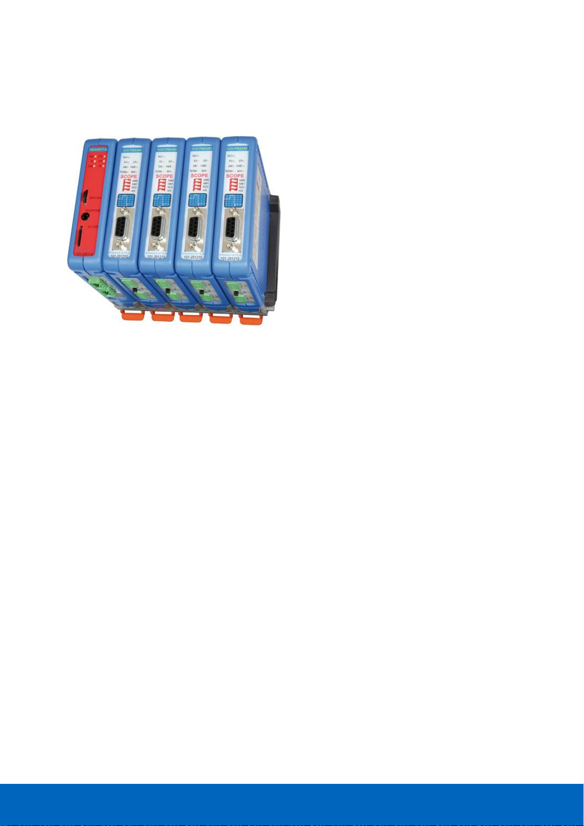
ComBricks™ - The first PROFIBUS and PROFINET-based
automation system that unites network components, permanent
monitoring with ProfiTrace and remote I/O.
ComBricks is a modular system that allows a mix of automation
components on a backplane. Repeater modules can be inserted
next to a PROFIBUS slave and at the same time, in a web browser
over Ethernet, the condition of the installation can be remotely
inspected with ProfiTrace OE.
1.2 Application areas
• Remote maintenance station with ProfiTrace OE
• Modular repeater backbone with hot swap
• Transparent data hub (repeaters, fiber optic, RS-485-IS, DP slave, PROFINET, etc.)
1.3 Product features
• Drives 32 modules (10 high-speed modules)
• Wide range of modules available
• Hot swap and extendible
• Powerful web server
• ProfiTrace OE for monitoring 4 networks
• Multi-language
• DIN-rail mounting
• IP 20
Page 11
ComBricks User Manual v6.4.0 | January 18| © PROCENTEC 11/219
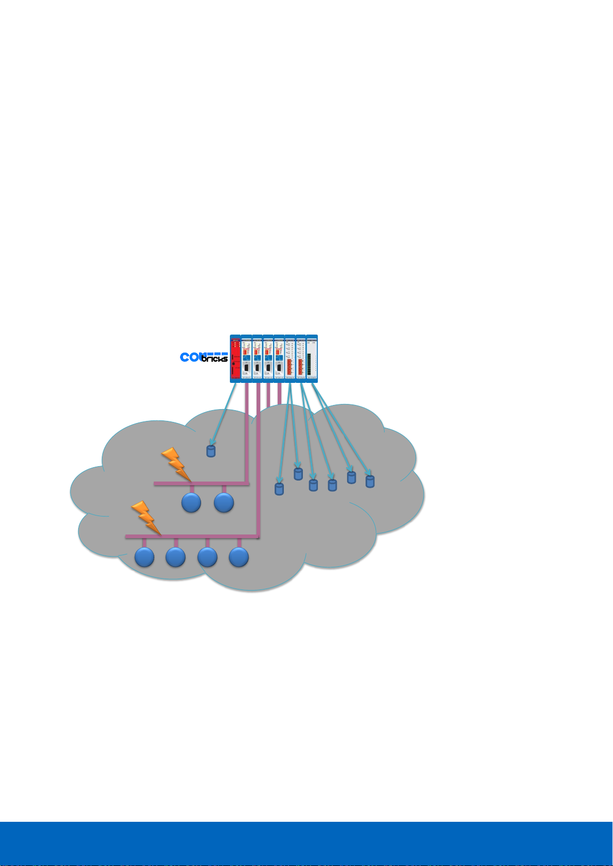
1.4 Modular PROFIBUS repeaters
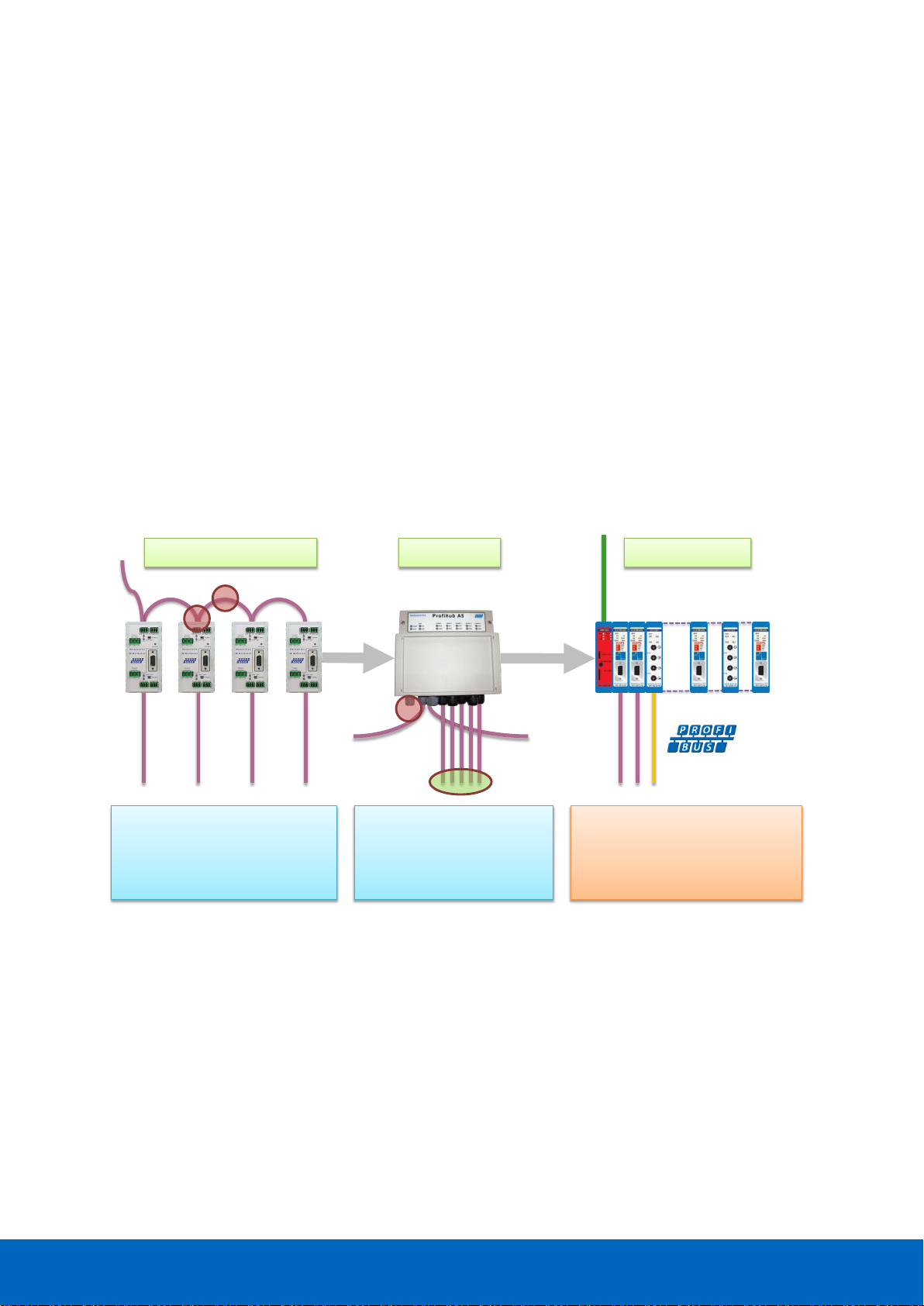
The current trend in PROFIBUS projects is to use segmentation with repeaters, fiber optic and ProfiHubs to
bridge the common faults of the end-user concerning his cabling difficulties. ComBricks adds another important
element; the creation of modular and random repeater hubs which can be maintained remotely with a
permanent internal ProfiTrace (see Fig. 1).
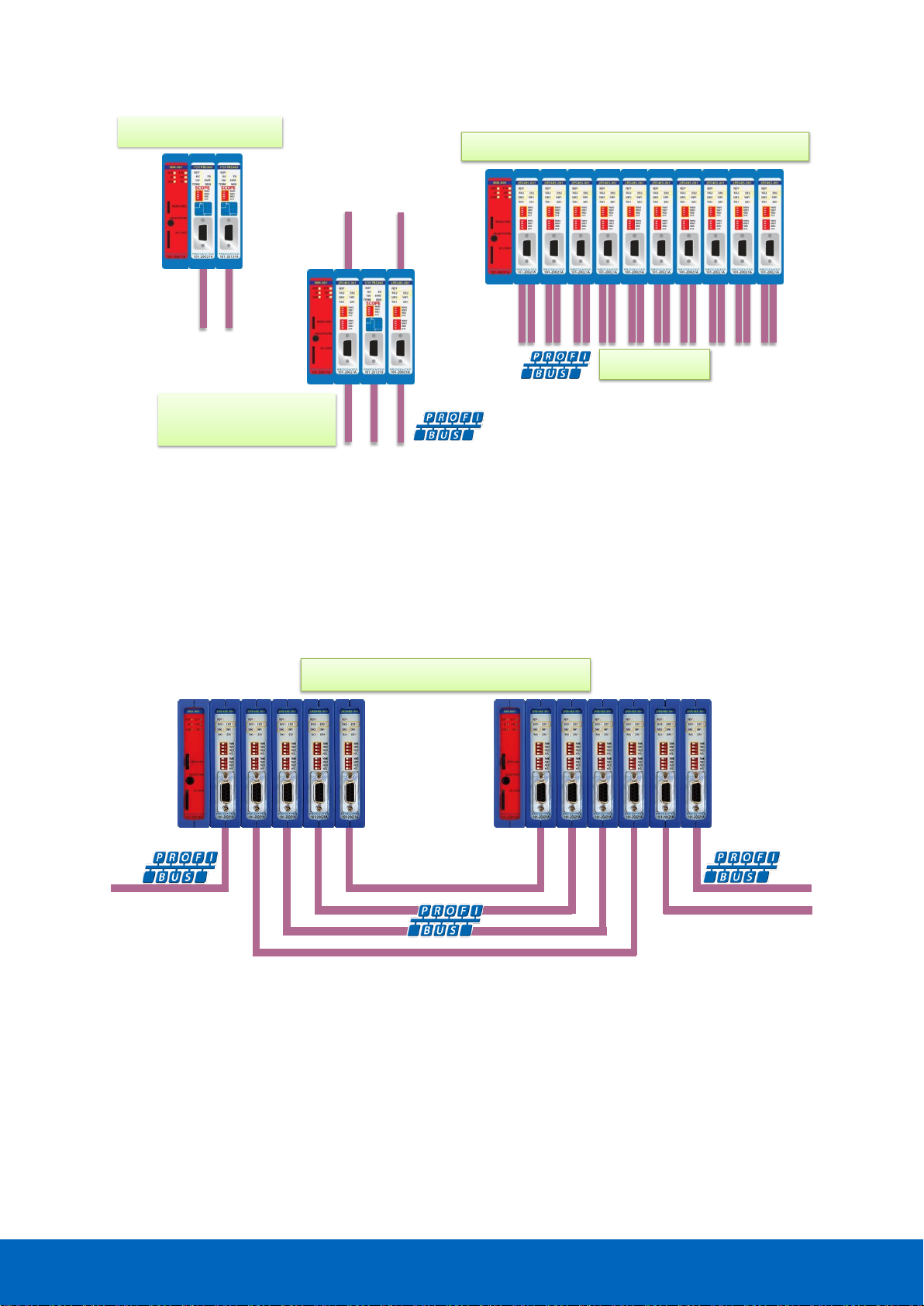
ComBricks is based on a backplane which can hold up to 10 hot swap repeater modules. Each module has one
or two channels (so a total of max 20 galvanic isolated transparent segments). Every channel can handle 31
PROFIBUS stations and maximum 1200 m cable length (depends on the baudrate). Fig. 2 illustrates some
configurations.
Each channel has a fail-safe circuit which ensures that the remainder of the PROFIBUS network continues to
operate correctly and that the availability of the installation remains optimal.
The connection of the bus cable allows for a high degree of flexibility as the repeater modules contain both a 9pin and screw connector.
It is possible to dynamically exchange equipment during operation. ComBricks is ideal for flow meters, pH
analysers, actuators, drives and especially motor control centres that make use of drawer systems.
ProfiHubsStandard repeaters
- 1 Meter rule problems
- Termination problems
- Power supply overload
- Costs and installation time
- 5 fixed channels
- RS 485 only
- No asset management
- Single power supply
COMbricks
ProfiTrace OE
- Modular and hotswap
- ProfiTrace over Ethernet
- Bus redundancy
- DTM, OPC, SNMP, HTTP
Fig. 1 - Latest trend in segmentation
Page 12
ComBricks User Manual v6.4.0 | January 18| © PROCENTEC 12/219
1.4.1 Cable Redundancy
The bus redundancy technology of the repeater modules is very advanced. A redundant system can be built
using 10 parallel cables. This architecture provides extremely high availability. Most suppliers only allow 2
cables (see Fig. 3).
redundant channels
Maximum 10 redundant channels
1 channel repeaters
2 segments
3 segments
Mix of 1 channel and
2 channel repeaters
2 segments
Maximum 10 modules (2 channel repeaters)
20 segments
Fig. 2 - Repeater configuration examples
Fig. 3 - Redundancy configuration example
Page 13

ComBricks User Manual v6.4.0 | January 18| © PROCENTEC 13/219
1.4.2 Comparison between ProfiHub and ComBricks
ProfiHub A5 and B5
(simple)
ComBricks
(flexible and high-tech)
• One component
• PROFIBUS
• RS-485 only
• Easy installation
• IP 65 version
• Low cost
• Modular
• Multi interface
• Multi network
• ProfiTrace OE
• Asset management
• Light weight
1.4.3 Typical applications
• Repeaters with permanent ProfiTrace
• Removable drives and motors
• Star, tree and bus structured networks
• Motor control centers (drawers)
• Redundancy for high availability
• EMC vulnerable applications
• Spur lines
• Isolator for sensitive devices
Page 14

ComBricks User Manual v6.4.0 | January 18| © PROCENTEC 14/219
1.5 ProfiTrace OE - Remote monitoring in a web browser
Permanent and simultaneous monitoring of 4 PROFIBUS networks is a powerful feature of ComBricks. Global
projects and a shortage of (qualified) technical staff members are causing significant capacity problems.
ComBricks offers a solution by remotely monitoring PROFIBUS installations over the Internet and alerting the
user by email.
The user can simply connect surrounding PROFIBUS networks and every network can be set to a unique
baudrate. The modular technology of ComBricks enables the network to be monitored when multiple repeater
modules are installed. All transparent messages from the backplane are constantly analysed.
Up to 10 Repeater modules with 2 channels each (20 galvanic isolated segments in total) can be inserted into
the backplane. Using DIP switches or the web server, repeater modules can be assigned to a network group.
This ensures isolated communication from the repeaters which are assigned to other network groups; the
networks are not combined or connected in any way. Only the Head Station can see all networks groups.
1.5.1 Web server
A web server with a ProfiTrace shell visualizes the information in an understandable format (ProfiTrace OE).
Because of the web browser, additional software is NOT required and a constant connection with a PC to the
ComBricks is NOT necessary.
The monitoring and logging is performed by the repeater modules which are inserted in the backplane.
ComBricks is the first system that has integrated a busmonitor in network components. Deploying ComBricks
repeaters for regular automation means automatic availability of ProfiTrace OE.
Monitoring 4 networks
Monitoring 4 networks
Monitoring 4 networks
Worldwide access
to any COMbricks
Page 15

ComBricks User Manual v6.4.0 | January 18| © PROCENTEC 15/219
1.5.2 Email
Email messages provide real-time alerts in the event of detected faults in the PROFIBUS communication. These
email alerts are easy to set up in the web server.
1.5.3 Channel List
A brand new functionality within ProfiTrace OE is the Channel List. It gives a detailed overview of all repeater
channels (segments) and all connected stations.
1.5.4 Comparison between ComBricks and ProfiTrace 2
The application area for ComBricks (ProfiTrace OE) compared to ProfiTrace 2 is completely different. ProfiTrace
OE should be seen as a watchdog and ProfiTrace 2 as the mobile analyzer to do on-site work.
ProfiTrace 2
(troubleshooting on-site)
ComBricks
(watchdog)
• USB (power supply)
• Mobile
• Software
• C1 Master
• Triggers and filters
• Large file recording
• Reporting
• Fast
• Ethernet / Internet
• Permanent installation
• Web server
• Multi network monitor
• Multi access
• Email and Log
Page 16
ComBricks User Manual v6.4.0 | January 18| © PROCENTEC 16/219
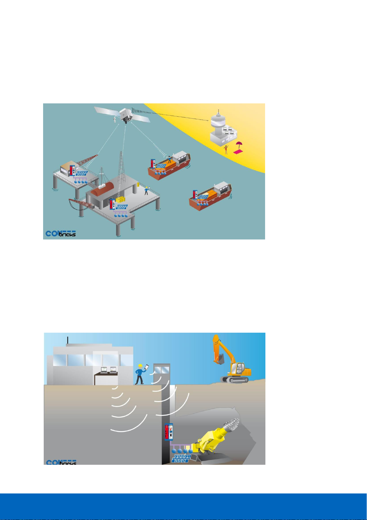
1.5.5 Offshore applications
With satellite internet offshore PROFIBUS networks can be remotely monitored. Emails can inform the
mainland about the status of the installation.
These applications simplify maintenance and eliminate the hassle to fly an expert over to fix a possible
problem. On the LAN local technicians can also monitor the networks.
1.5.6 Mining applications
Because of the depth, gasses and inaccessible areas, ComBricks is required to keep the control room and the
experts on a distance to monitor the PROFIBUS installations.
Multiple WLAN routers can bring Ethernet up to the surface.
With DTM technology the devices can also be diagnosed and parameterized.
Fig. 4 - Offshore applications
Fig. 5 - Mining applications
Page 17

ComBricks User Manual v6.4.0 | January 18| © PROCENTEC 17/219
1.5.7 Robot cells
Robot cells are hazardous environments with many safety zones. Crossing a safety border can cause a machine
shutdown and restarting can take a long time. Measuring PROFIBUS remotely decreases costs and improves
human safety.
Fig. 6 - Robot cells
1.5.8 Logistics
In demanding high-speed applications, ComBricks is ideal. The technician does not have to touch the
installation and can measure the network from a distance. This is also convenient if the installation is behind a
high-security zone such as baggage handling systems at airports, or parcel handling systems.
Fig. 7 - Baggage handling or parcel systems
Page 18

ComBricks User Manual v6.4.0 | January 18| © PROCENTEC 18/219
1.5.9 Traffic control
When distance and downtime are critical factors, ComBricks can be very helpful. Difficult to reach speed
indicators above the highway can be monitored from the road-side control cabinet, or even from the control
room.
Fig. 8 - Traffic control applications
1.5.10 Cranes
Many harbour cranes use PROFIBUS. There cranes are huge and sometimes hard to reach. The whole crane can
be monitored remotely, which is especially useful if the crane is equipped with a WIFI connection.
Fig. 9 - Crane applications
Page 19
ComBricks User Manual v6.4.0 | January 18| © PROCENTEC 19/219
1.5.11 Other applications
• Cross border installations
• Water treatment
• Long commissioning and test cycles
• 24-7 service contracts
1.6 Output control
Relay- and digital output modules can be configured to respond directly to bus problems, such as bus voltage
too low, retries, syncs, master lost, diagnostics, etc.
This offers a multitude of applications to directly and independently act on the machinery when the bus
communication becomes unreliable. Especially when safety, human lives or the environment are at stake.
Power switches, hold switches, indicators, backup systems and LED towers are a few examples of machine
parts that can be hooked up to the relays. ComBricks is the only monitoring product that has the capability to
respond directly on the hardware with multiple relays.
• The Head Station already contains 1 relay.
• The relays can also be configured to be switched manually or on time.
24 55 834
2 3
Segment 2
Segment 1
Power switches, Hold switches,
Indicators, Backup systems,
Device I/O, Doors,
LED towers, etc.
Retries
Syncs
Bus voltage low
Lost
Diagnostics
Repeaters I/O
Fig. 10 - Output control
Page 20

ComBricks User Manual v6.4.0 | January 18| © PROCENTEC 20/219
1.7 CommDTM
The FREE ComBricks CommDTM offers FDT 1.2 based asset management tools a powerful Ethernet passthrough to access PROFIBUS devices which are connected on ComBricks repeater modules.
The internal DP-V1 class 2 masters are able to drive 2 out of 4 networks. When a CommDTM connection is
closed, the user can enter another network. The 2 active networks are managed by 1 or 2 PC Ethernet
connections.
The CommDTM provides the same auto baudrate detection facilities as the famous ProfiCaptain. It detects all
busparameters before it goes online. An available master address is required.
CommDTM
CommDTM
Device DTM
PROFIBUS DP
Device DTM
PROFIBUS PA
FDT Applications ProfiTrace OE
Fig. 11 - CommDTM structure
Page 21

ComBricks User Manual v6.4.0 | January 18| © PROCENTEC 21/219
2 Quick start
2.1 Quick start checklist
This checklist lists all the steps to a quick usage of ComBricks.
STEP 1: Provide the Head Station with the latest firmware. (7)
STEP 2: Prepare the backplane with the amount of required backplane units. (2.2)
STEP 3: Click the assembled backplane on the DIN-rail. (2.2)
STEP 4: Insert the Head Station in the most left slot. (2.3)
STEP 5: Insert the other modules in the remaining slots. (2.3)
STEP 6: Configure the repeater modules to their appropriate networks. (2.4)
STEP 7: Wire the repeater modules with PROFIBUS cables. (2.5)
STEP 8: Power the Head Station. (2.6)
ComBricks units with Head Stations type 1A are now operational and no further steps have to be
taken. For type 1B and 1C Head Stations proceed with the next steps.
STEP 9: Insert an Ethernet cable in the Head Station.
STEP 10: Set the IP address to the required value. (2.7 + 2.8)
ComBricks units with Head Stations type 1B and 1C are now operational, ProfiTrace OE is
autonomously logging PROFIBUS events. After these basic steps ComBricks can be further configured
through the web server.
STEP 11: Checking the modules and administrative info in the web server. (2.9)
STEP 12: Testing ProfiTrace OE on the PROFIBUS installation. (2.10)
Page 22

ComBricks User Manual v6.4.0 | January 18| © PROCENTEC 22/219
2.2 Prepare the backplane
Click the fixed backplane on the DIN-rail and add additional backplane units to the right side if required (see
Paragraph 3.3 and 3.4).
2.3 Insert modules
Insert the required modules in the slots of the fixed backplane (see Paragraph 3.6). The Head Station with the
red front plate should be placed in the most left slot (with the large connector). Place the other modules in the
remaining slots. The slots have a polarity and can only be inserted one way.
2.4 Configure the repeater modules
Configure the repeater modules to their appropriate networks. This can be done with the dipswitches located
at the front of the module (see Paragraph 3.10.1) or with the software settings in the web server (see
Paragraph 4.5).
2.5 Wire the repeater modules
Connect the PROFIBUS cables to the repeater modules (see Paragraph 3.11).
2.6 Power the Head Station
Provide a 24 VDC power supply to the Head Station through one of its 2 power connectors (see Paragraph 3.8).
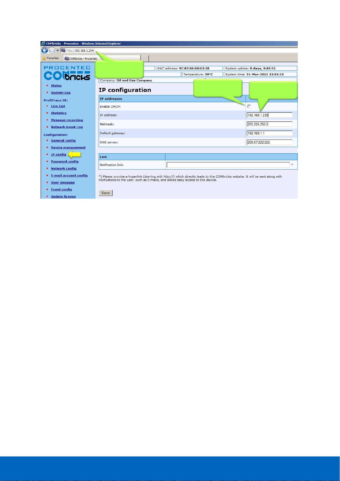
2.7 Customizing the IP number through the web server
The default IP address of the Head Station is 192.168.1.254. Follow the steps below to customize the IP address
of the Head Station:
STEP 1: Insert an Ethernet cable in the Head Station which is connected to the enterprise LAN or
directly to the PC.
STEP 2: Make sure the IP address of your PC is on the same subnet as the switch (192.168.1.xxx)
STEP 3: Open your web browser and enter 192.168.1.254 in the address field. This is default IP
address of the ComBricks.
STEP 4: The web server of the ComBricks will appear.
STEP 5: Click in the menu on the left on "IP config".
STEP 6: Update the IP settings and confirm it by clicking on "Save" (see Fig. 12).
STEP 7: The web page will now reload with the new IP address.
Page 23
ComBricks User Manual v6.4.0 | January 18| © PROCENTEC 23/219
The Notification link name is included in the event emails so that the user can directly jump to the specific
ComBricks unit without knowing its local IP number. An example is: www.boiler5.oag.com. The router of the
network or the internet server has to reroute this name to an IP number.
New IP address +
other settings
Tick this checkbox
if DHCP is required
Current IP address
Fig. 12 - Customizing the IP address in the web server
Page 24
ComBricks User Manual v6.4.0 | January 18| © PROCENTEC 24/219
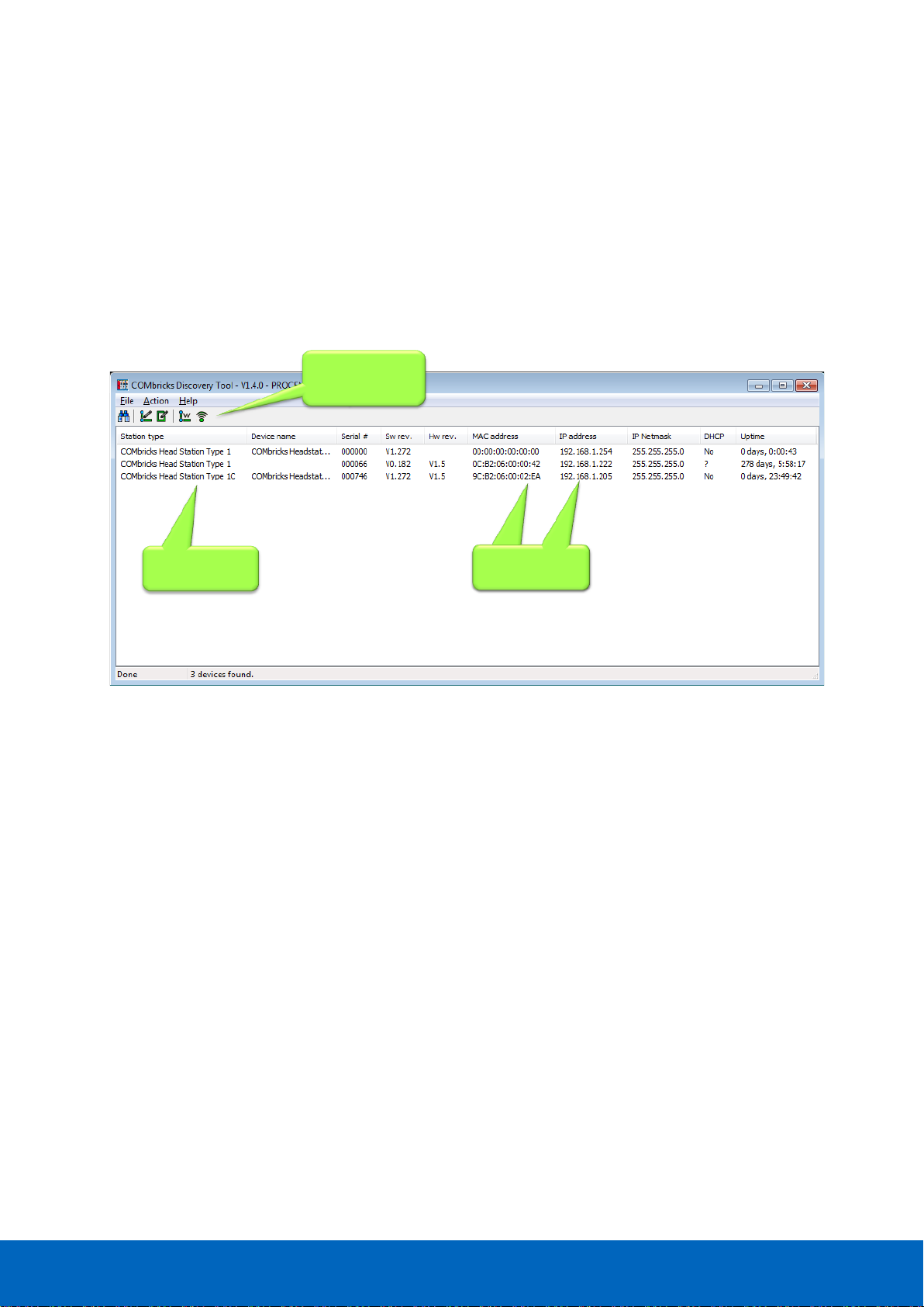
2.8 Customizing the IP number through the Discovery Tool
The ComBricks Discovery Tool can be downloaded from www.ComBricks.com.
After start-up all the available ComBricks units can be discovered and directly customized with the required IP
address (see Fig. 13).
The Discovery Tool works on an enterprise LAN, WLAN and with a direct cable between ComBricks and PC.
If you are not sure which ComBricks you are customizing, the LEDs can be flashed with a button in the
Discovery tool (flashing). The LEDs will blink for 5 seconds to give the user a visual confirmation.
Fig. 13 - ComBricks Discovery Tool
It is recommended to have only one network interface connection active (only wireless or only
wired). In some cases the Discovery tool does not list all the ComBricks units when multiple network
interfaces are active.
Head Stations
MAC and IP
addresses
MAC and IP
addresses
Scan and
configuration
options
Page 25
ComBricks User Manual v6.4.0 | January 18| © PROCENTEC 25/219
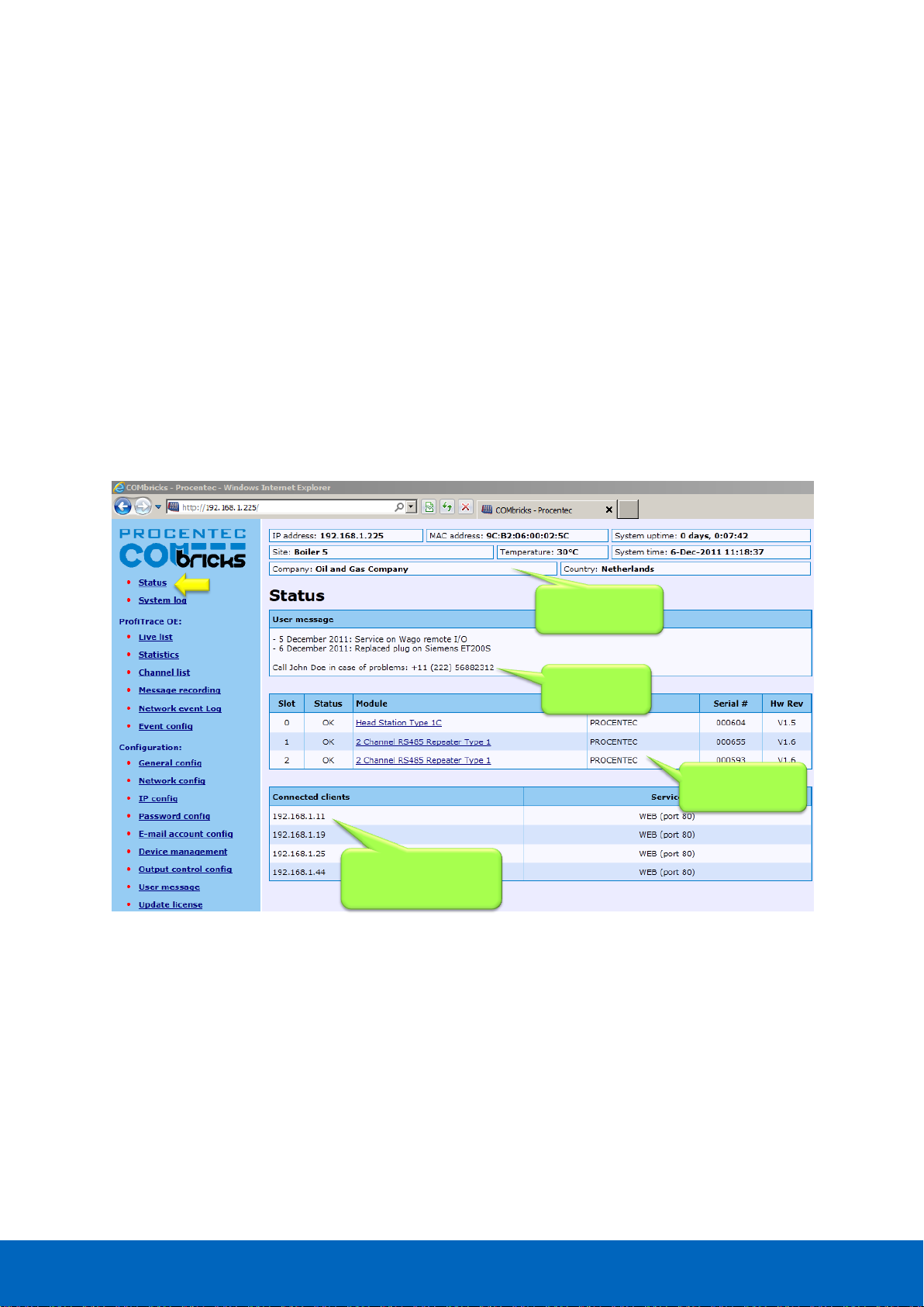
2.9 Checking the modules and the administrative info in the web server
After customizing the IP address, the modules can be checked in the web server. Click on "Status" to see an
overview of the available modules and their respective description + version numbers (see Fig. 14).
Modules can be inserted and removed during operation. A change in hardware should be directly visible in the
Status screen.
On the top of the screen the administrative info is also visible (see Fig. 14). If the administrative information
has to be altered, it can be done by clicking on "General config".
On the bottom of the screen the connected clients with this ComBricks are displayed.
All connections are listed here:
• Web connections
• FTP connections
• CommDTM connections
• Telnet connections
• ProfiTrace Streaming connections
Fig. 14 - Overview of the available modules
Connected PCs and
other communication
devices
Remote
information
Inserted modules
in the system
Messages left
by the user
Page 26
ComBricks User Manual v6.4.0 | January 18| © PROCENTEC 26/219
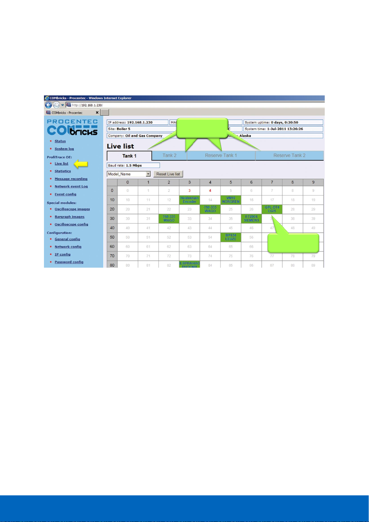
2.10 Testing ProfiTrace OE on the PROFIBUS installation
When the repeaters are wired to the PROFIBUS installation, ProfiTrace OE can be tested in the web server.
Click on "Live List" and the respective networks. A Live List with devices should appear (see Fig. 15).
See Chapter 5 for more information on how to use ProfiTrace OE.
Similar Live List as
ProfiTrace 2
Monitoring 4
networks
Monitoring 4
networks
Monitoring 4
networks
Monitoring 4
networks
Fig. 15 - ProfiTrace OE Live List
Page 27

ComBricks User Manual v6.4.0 | January 18| © PROCENTEC 27/219
2.11 Resetting the Head Station
By means of the "Menu Nav" switch on the front of the Head Station (see Fig. 16), ComBricks can be reset,
warm started or loaded with configuration data. Please follow the procedure described in Paragraph 6.5.
The following selections are possible:
• Read settings from SD card
• Save settings on SD card
• Clear password
• Reset to factory defaults
• Warm start
Fig. 16 - Menu-switch
Page 28
ComBricks User Manual v6.4.0 | January 18| © PROCENTEC 28/219
3 Installation instructions
3.1 Location
ComBricks can be installed everywhere in a non-hazardous area that complies with IP 20 (DIN 40 050) and a
specified maximum operating temperature of +60
o
Celsius. Avoid placing two ComBricks sets above each other;
the generated heat of the lower set will add to the ambient temperature for the upper set. Furthermore, make
sure the generated heat can disperse by using forced ventilation or active cabinet cooling.
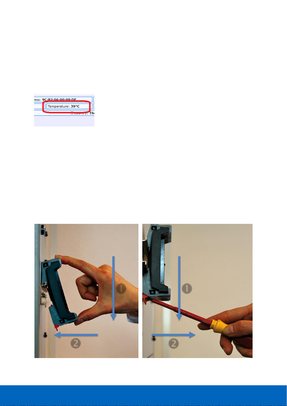
Please note: the temperature displayed in the webserver is the temperature
inside the Head Station, not the ambient temperature.
3.2 Position
ComBricks can only be installed horizontally, with the cables pointing down. In this position the generated heat
of the modules can escape through the grid in the top of the housing. It is also easier to read the status LEDs in
the horizontal position.
3.3 Mounting and un-mounting backplane units
The backplane of the ComBricks has to be mounted on 35 mm DIN-rail with a minimum width of 50 mm to fit a
fixed backplane for 2 modules.
Fig. 17 illustrates how to mount and dismount the backplane on and from the DIN-rail. For the un-mounting an
appropriate screwdriver is required.
Fig. 17 - Mounting (pull-down + push) Un-mounting (click tap + pull)
Page 29
ComBricks User Manual v6.4.0 | January 18| © PROCENTEC 29/219
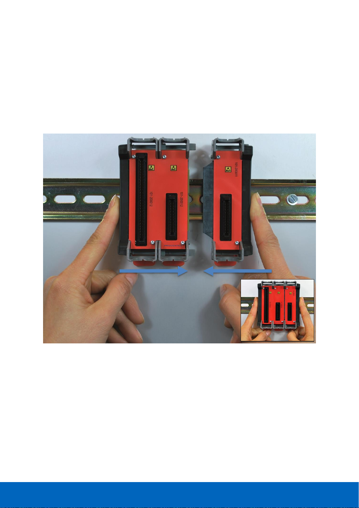
3.4 Adding backplane units
The additional backplane units as described in Paragraph 3.3. To merge them remove the plastic covers on the
side of the backplane units that have to be merged. Push both backplane units together until no more
movement is possible (see Fig. 18).
Do not add or remove backplane units while the backplane is powered!
This can cause serious damage to the ComBricks set.
Fig. 18 - Adding backplane units
Page 30
ComBricks User Manual v6.4.0 | January 18| © PROCENTEC 30/219
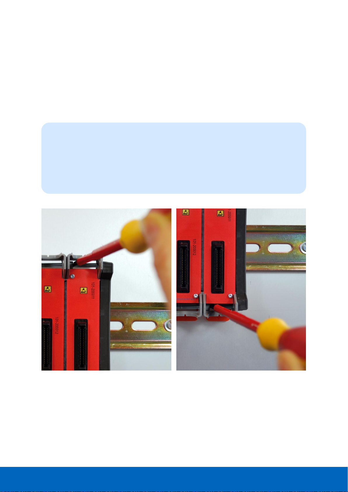
3.5 Detaching backplane units
Detaching backplane units is a delicate procedure that should be done according the description
below and Fig. 19 in order to prevent damages.
Do not add or remove backplane units while the backplane is powered!
This can cause serious damage to the ComBricks set.
Fig. 19 - Detaching backplane units
STEP 1: Push the top arm down with a screwdriver and delicately pull the top of the backplane unit
that has to be removed. The arm should now be unlocked.
STEP 2: Push the bottom arm down with a screwdriver and delicately slide the bottom of the
backplane that has to be removed. The arm should now be unlocked.
STEP 3: Slide the backplane unit away from the section that remains.
Page 31

ComBricks User Manual v6.4.0 | January 18| © PROCENTEC 31/219
3.6 Inserting modules
Push and click the modules in the slots of the backplane (see Fig. 20).
The Head Station (with the red front plate) should be placed in the most left slot (with the largest connector)
and the other modules in the remaining slots.
When the modules are inserted the correct way, a sharp clicking sound should be heard during the push.
Modules can be inserted during operation.
The slots have a polarity and fit only one way.
3.7 Removing modules
To remove a module press the keys on both sides of the module (this has to be done with 2 hands). When both
keys are pressed, pull the module out of the slot (see Fig. 21).
Fig. 20 - Inserting modules
Page 32

ComBricks User Manual v6.4.0 | January 18| © PROCENTEC 32/219
Modules can be removed during operation.
1 Slot between 2 modules can remain empty when modules
are removed during operation. Modules at the end of the
backplane can always be removed (1-by-1).
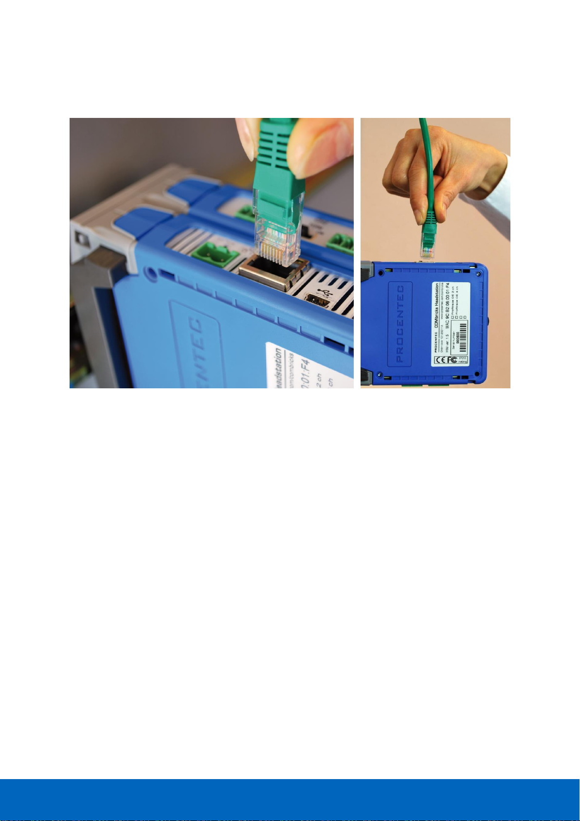
3.8 Wiring Ethernet
The Ethernet connector is located on the top-side of the Head Station. The connector contains LEDs that
indicate linkup (green) and reception of data (orange).
It is recommended to use a cable/RJ45 plug with grounding/foil due to the nature of industrial applications.
The Ethernet interface complies with standard Ethernet guidelines. The maximum cable length from ComBricks
to switch/device is 100 meter.
Fig. 21 - Removing modules
Page 33
ComBricks User Manual v6.4.0 | January 18| © PROCENTEC 33/219
The MAC address is printed on the side of the Head Station.
Fig. 22 - Wiring Ethernet
Page 34

ComBricks User Manual v6.4.0 | January 18| © PROCENTEC 34/219
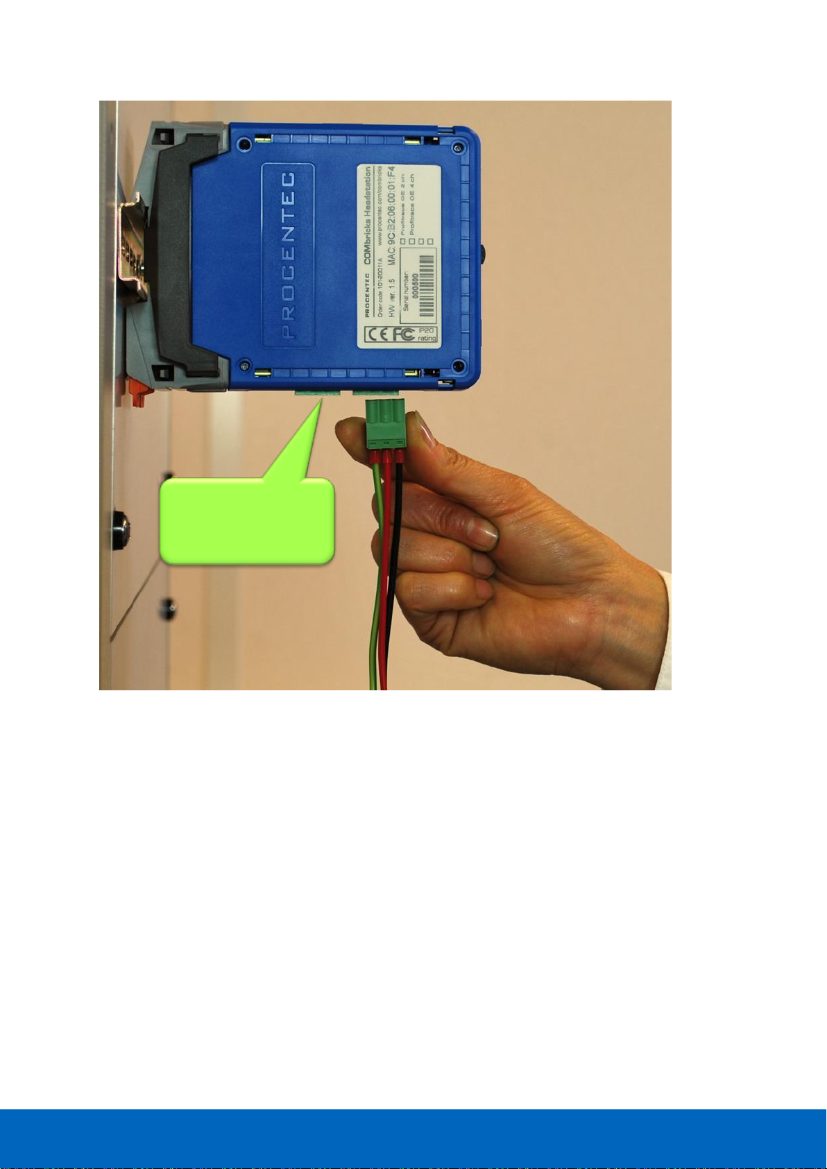
3.9 Power Supply
The Head Station contains two 3-pin screw type power connectors on the bottom. If power redundancy is NOT
required, either one can be used.
The layout is as follows (when the wires are pointing down):
1 = - (left)
2 = + (middle)
3 = SH (right)
The power supply must comply with the following specifications:
• Voltage: 10.8 .. 26.4 VDC
• Current: Min. 800 mA
• Wire diameter: < 2.5 mm
2
3.9.1 Procedure
To connect the 24 VDC supply to the 3-pin screw-type terminal, proceed as follows:
To connect the power supply a 3 mm screwdriver is required.
3.9.2 Testing and commissioning
If the power is switched ON it can be diagnosed by the following indicator procedure:
• All LEDs on the Head Station should be shortly ON.
• The RDY LED should be shortly Blinking.
• The SD LED should be ON (if an SD card is inserted).
• The RDY LED should be ON (also on other inserted Modules).
STEP 1: Strip the insulation of the conductors of the 24 VDC power supply.
STEP 2: Secure the conductors in the screw-type terminal.
STEP 3: Insert the entire connector block in the power socket (see Fig. 23).
Page 35
ComBricks User Manual v6.4.0 | January 18| © PROCENTEC 35/219
Redundant power
supply option
Fig. 23 - Head Station power supply
Page 36

ComBricks User Manual v6.4.0 | January 18| © PROCENTEC 36/219
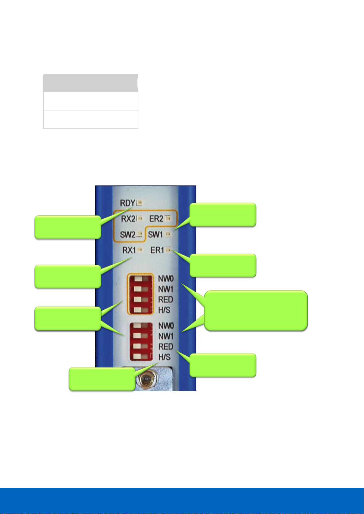
3.10 Configuring repeater modules
The repeaters can be configured using the dipswitches located at the front of the module or the web server.
3.10.1 Customizing the PROFIBUS network (NW0/NW1)
Set these dipswitches to the following positions to customize a network number for a specific PROFIBUS
network.
NW0
NW1
Network
LEFT
LEFT
1
RIGHT
LEFT
2
LEFT
RIGHT
3
RIGHT
RIGHT
4
When software settings are preferred these dipswitches do not have to be set.
3.10.2 Redundancy (RED)
Set this dipswitch to enable the redundancy group for the channel.
RED
Redundancy
LEFT
OFF
RIGHT
ON
When software settings are preferred this dipswitch does not have to be set.
Page 37
ComBricks User Manual v6.4.0 | January 18| © PROCENTEC 37/219
3.10.3 Hardware or software settings (H/S)
Set this switch to enable hardware (dipswitches) or software settings.
H/S
Settings
LEFT
Hardware
RIGHT
Software
When software is enabled, all switch settings
are overruled. The settings are saved in the internal
memory of the Head Station.
Dipswitches or web
server settings
Redundancy for the
current network
Network 1: NW0 = L, NW1 = L
Network 2: NW0 = R, NW1 = L
Network 3: NW0 = L, NW1 = R
Network 4: NW0 = R, NW1 = R
Channel 1 and
Channel 2
Channel 2 and
Channel 1
Communication
error on Channel x
Termination ON
on Channel x
Data received on
Channel x
Repeater Module
status
Network 1: NW0 = L, NW1 = L
Network 2: NW0 = R, NW1 = L
Network 3: NW0 = L, NW1 = R
Network 4: NW0 = R, NW1 = R
Fig. 24 - Dipswitches and LEDs of the repeaters
Page 38
ComBricks User Manual v6.4.0 | January 18| © PROCENTEC 38/219
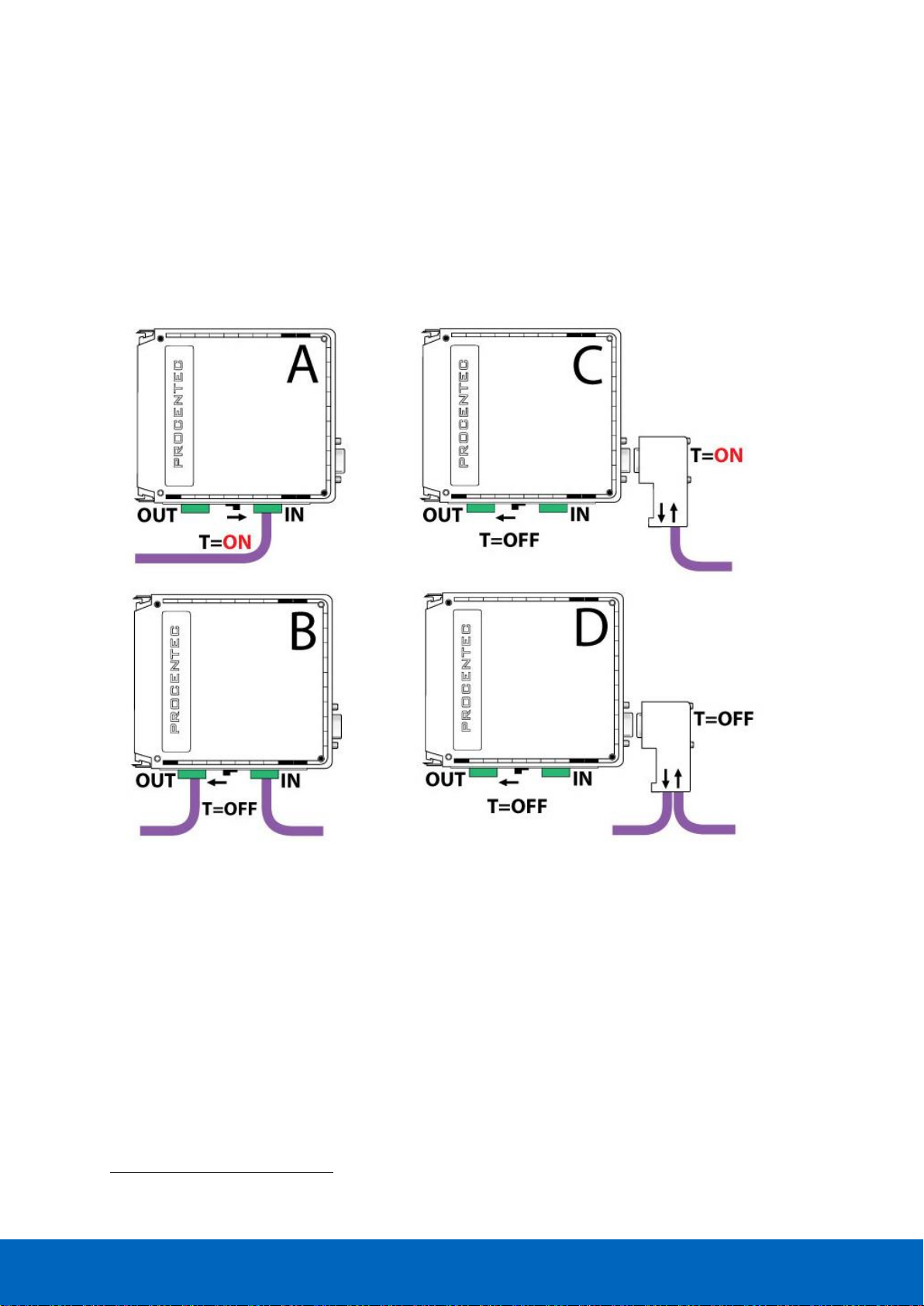
3.11 Wiring repeater modules
The PROFIBUS cable should be wired to the repeaters according to the PROFIBUS guidelines with suitable cable
for the application you are using.
Regular and SCOPE repeater modules are equipped with screw terminals and a DB9 connector for the bus
connection. Both are linked with each other, but it is not recommended to use them both1.
Fig. 25 illustrates 4 recommended connection topologies for the repeater modules.
1
Because of the PROFIBUS spur lines limitations it is not recommended to use the screw terminal
simultaneously with the DB9 connector.
Fig. 25 - Repeater connection topologies (old modules only)
Page 39
ComBricks User Manual v6.4.0 | January 18| © PROCENTEC 39/219
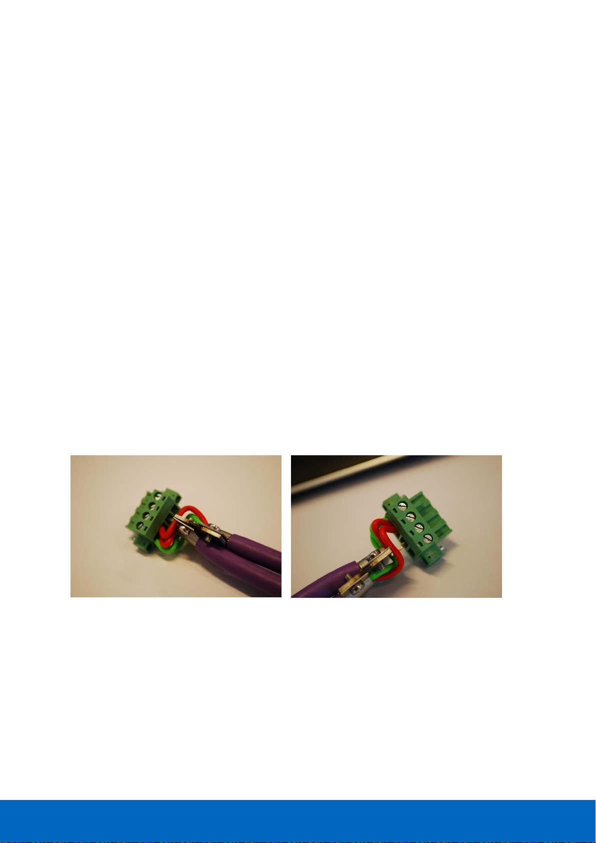
3.11.1 Screw terminals
• With a 1 channel repeater module, the channel is marked CH1.
• With a 2 channel repeater module, the channels are marked CH1 and CH2.
NOTICE
Since March 2014 the 1 Channel, 2 Channel and Scope Repeater modules are fitted with new, more robust
screw terminals.
Old modules: The channels (CHx) have 2 screw terminals (IN and OUT, for the bus connection) and a
termination switch.
Always use the ‘IN’ connector when the repeater module is the first or last on the segment. The termination
should be set to ON (see Fig. 25 - configuration A).
New modules: The channels have 1 screw terminal and a termination switch. In most cases, the channel
starts here so the termination must be set to ‘ON’. If the channel is not the beginning, use the DB9
connector, see paragraph 3.11.2. Alternatively, use the dual ground clip (supplied with the new models) to
install two cables in one screw terminal, see Fig. 26.
Only in configuration A of Fig. 25 the on-board termination should be set to ON. In configurations B and D the
repeater module is in the middle of the segment (OFF).
Pin layout of the screw terminals
Pin “A”: Green wire
Pin “B”: Red wire
Pin “SH”: Cable shielding OR
Pin “I”: Cable shielding
Fig. 26 - Use the Dual Ground Clip to connect two PROFIBUS cables in one screw terminal
Page 40

ComBricks User Manual v6.4.0 | January 18| © PROCENTEC 40/219
3.11.2 DB9 connector
The bottom channel (CH1) is additionally equipped with a DB9 connector to offer an alternative connector for
standard 9-pin PROFIBUS plugs (1-on-1 with the screw terminals).
When the DB9 connector is utilized and located at the end of the segment, it is recommended to use the
termination on the DB9 connector and NOT on the repeater module (see Fig. 25 - configuration C)2
To connect the PROFIBUS cable to the repeater modules (screw terminals) a 2.5 mm screwdriver
(max. 0.4 mm) is required.
3.11.3 Testing and commissioning
If the channel recognizes valid PROFIBUS messages from 1 or more connected devices, the RX LED of this
channel should be blinking and ER should be OFF.
When the termination of a specific channels is set to ON, the SWx LED should be ON.
2
The plug is the best place to activate the termination! When you remove the connector from the module you
still have the termination in the plug which is attached to the bus cable. It is true that the termination is not
powered by 5V (which is always required), but better an unpowered termination than nothing at all.
Page 41

ComBricks User Manual v6.4.0 | January 18| © PROCENTEC 41/219
4 Web server
To access the web server of ComBricks, open your web browser and enter the IP address that has been setup
(after purchase or reset the default IP address is 192.168.1.254). In the Discovery Tool you can find a button to
access the web server with the default Windows browser.
If a User password has been setup a screen will appear to login first in order to access the web
server. If only the Administrator password has been setup it is not necessary to login to directly, but
when settings are altered you must be logged in (See Paragraph 4.8).
Some web pages described in this manual
are only accessible with certain Head Station
types, licenses or firmware versions.
After the web page has been loaded, the pages of the web server can be browsed by clicking on the items in
the menu on the left side of the screen. The next paragraphs will explain the primary web server pages.
The web server can handle 20 simultaneous client
connections. When all 20 are utilized, the connection
with the ComBricks could become relatively slow.
The minimum version requirements for Web browsers are:
• Firefox 2.0 (24 October 2006)
• Internet Explorer 6.0 (27 Augustus 2001)
• Google Chrome 1.0 (24 April 2009)
Page 42

ComBricks User Manual v6.4.0 | January 18| © PROCENTEC 42/219
4.1 Status
The 'Status' screen is the first web page that appears when the web server is accessed. This page gives an
overview of the available modules and their respective description + version numbers (see Fig. 27).
Modules can be inserted and removed during operation. Changes in hardware should be directly visible in the
Status screen.
The 'User message' with custom messages/info is also displayed here (see Fig. 27).
On the top of the screen the network and site info can be inspected (see Fig. 27).
On the bottom of the screen the connected clients with this ComBricks are visible (see Fig. 27).
Most of the module types offer their specific status screen. Click on the link (name in the module column) and
the respective web page will be displayed (see Fig. 28).
Head Stations: 1A, 1B, 1C
Firmware: V1.140 and higher
Login: User or Administrator
Connected PCs and
other communication
devices
Remote
information
Inserted modules
in the system
Messages left
by the user
Fig. 27 - Status screen
Page 43

ComBricks User Manual v6.4.0 | January 18| © PROCENTEC 43/219
Power redundancy status
Current consumed
by the modules
SD card status
Fig. 28 - Example of a module status
Page 44

ComBricks User Manual v6.4.0 | January 18| © PROCENTEC 44/219
4.2 Channel list
A helpful utility is the Channel list. This page visualizes a graphical overview of all stations in the network and to
which network module they are connected. It is almost comparable with a logical topology scan (see Fig. 29).
Communicating
devices with Live
List colours
Inserted network
modules and the
available channels
Network filters
Inserted network
modules and the
available channels
Show colour
legend
Head Stations: 1A, 1B, 1C
Firmware: V1.152 and higher
Login: User or Administrator
Fig. 29 - Channel list
Page 45

ComBricks User Manual v6.4.0 | January 18| © PROCENTEC 45/219
4.3 System log
The system log saves ComBricks events. When this page is accessed all the ComBricks events are displayed. It
can be downloaded as text file and cleared/deleted (see Fig. 30). You cannot change the system log in the web
server.
The 'System log' is;
• kept intact after a power down and continues its logs after a power-up.
• auto/live updating when this screen is accessed.
• saved on the SD card.
Head Stations: 1A, 1B, 1C
Firmware: V1.140 and higher
Login: User or Administrator
System events
Download and
Clear functions
Fig. 30 - System log
Page 46

ComBricks User Manual v6.4.0 | January 18| © PROCENTEC 46/219
4.4 General configuration
The basic settings of the ComBricks are customized on the 'General configuration' page. For optimal use of
ProfiTrace OE, it is important that the time is synchronized and the site info is sufficiently filled in (see Fig. 31).
If your ComBricks is connected to Internet or a local NTP server, use the NTP server synchronization for
automatic date & time update. This keeps your ComBricks always set to the right time (this option is available in
Head Station firmware v1.278 and up). If the ComBricks clock differs more than 10 seconds from the NTP clock,
a line in the system log is added.
The automatic time update occurs when the set interval has passed. The maximum interval that can be set is
1440 minutes, which corresponds to 24 hours. Please note that there is no option for auto-updating to Daylight
Saving Time (DST). This is because this is not used in Factory Automation. When an NTP server is used, the time
is always assumed to be winter time.
The display refresh rate has to be tuned to the bandwidth of the Ethernet connection. By default it is set to a 1
second automatic refresh. If the bandwidth is limited, it is recommended to increase this time or to switch the
automatic refresh OFF (see Fig. 31).
It is possible to select the start page which is first displayed when browsing to the Head Station IP address. You
can select the Main Status page, System Log page, Live List, Statistics, Channel list Message Recording or
Network Event log. You can also select for which network this should apply.
The interface language can be changed in the Preferred Language drop-down box. More languages will be
added in the future, which will become available in new firmware updates.
Remote info which is
displayed on every web
page
Settings related to the
Ethernet bandwidth and
start page
Language selection
Time synchronization
options . Use NTP for
automatic synchronization.
Head Stations: 1A, 1B, 1C
Firmware: V1.140 and higher
Login: Administrator
Fig. 31 - General configuration
Page 47

ComBricks User Manual v6.4.0 | January 18| © PROCENTEC 47/219
4.5 Network configuration
The network names and the assignment of the repeater modules are customized here. For optimal use of
ProfiTrace OE, it is important that correct and understandable network names are defined (see Fig. 32). The
network names are used in multiple components: ProfiTrace Live List, event emails, message recording, etc.
Each of the 4 Live Lists can be individually setup to a different time-out. The default value is 5 seconds. The
time indicates how long a slave will be displayed as green when it has lost communication to the master. After
the set time it will turn yellow if it has no communication anymore.
The network assignment of the repeater modules is also displayed and can be adjusted if software settings are
enabled (see Fig. 32). It is possible to assign a module to Network 1 to 4, or to disconnect it from the
backplanes. This makes it possible to create a multiplexed system, or temporarily remove certain slaves from
the PROFIBUS network.
Dipswitch settings are always primary to software settings.
Network selection:
1, 2, 3 , 4 or
Not Connected
Customizable
network names
Hardware or
software settings
Head Stations: 1A, 1B, 1C
Firmware: V1.252 and higher
Login: Administrator
Fig. 32 - Network configuration
Page 48

ComBricks User Manual v6.4.0 | January 18| © PROCENTEC 48/219
4.6 IP Configuration
The IP Configuration screen offers some basic IP settings.
The DHCP functionality can be enabled. If the ComBricks will be connected to a network where a DHCP server is
active, the settings can be automatically set into the ComBricks by enabling this feature. The IP address will be
set by the DHCP server.
If a fixed IP address is needed, enter it manually in the ‘IP address’ box. By default the IP address is
192.168.1.254. Next, enter the subnet mask, default gateway and DNS server according to the settings of the
network. For more information, contact the network administrator.
Please note that changing the DNS server address requires a soft-reboot of the Head Station before the new
setting becomes active. Soft-resetting the Head Station does not affect repeater modules; this is a separate
process. You can safely soft-reset the Head Station without disrupting the repeater-functionality.
4.6.1 Server port configuration
The ports of the following internal servers of the ComBricks can be changed:
• Web server (default port is 80)
• Streaming server (default port is 38888)
• CommDTM server (default port is 38890)
You can enter any port number between 1024 and 65535. Simply enter a valid port number and press ‘Apply’.
Changes will be effective immediately; no reboot is required.
Note about the Web server port: if you change the default port of the web server, you will lose the current
connection to the ComBricks. When the port is changed, the ComBricks will ask you if you want to connect to
the new port. If the Streaming or CommDTM server ports are changed, also change this on the client side and
(if applicable) update firewall rules and/or router setup. Contact your system administrator for this.
Head Stations: 1A, 1B, 1C
Firmware: V1.252 and higher
Login: Administrator
Page 49

ComBricks User Manual v6.4.0 | January 18| © PROCENTEC 49/219
4.7 Output Control
With the Output Control feature the user can directly respond to an event with the onboard relay in the Head
Station or the channels from output modules in the backplane. The web server offers 10 customizable controls
that can be set to the following behavior:
• Not active
• Manual ON/OFF Live toggle of the output channels
• Time Time ON and Time OFF
• PROFIBUS event Syncs, retries, bus voltage too low, redundancy failure, PA failure,
fiber optic failure etc.
• System event Redundant power change or ComBricks failures
After power down/up, the ComBricks loads and restores these settings.
It is recommended to have a security policy concerning passwords with this feature, because the
user is able to control REAL output points.
Head Stations: 1A, 1B, 1C
Firmware: V1.254 and higher
Login: User
Fig. 33 - Output Control
Page 50

ComBricks User Manual v6.4.0 | January 18| © PROCENTEC 50/219
4.8 Password setup and login
Passwords are NOT activated when the
product is purchased or reset and all menu
items are accessible and adjustable.
ComBricks supports 2 types of passwords;
• The Administrator password has to be set first.
• The passwords can have a length between 1 and 16 characters.
Fig. 34 illustrates the password setup web page.
4.8.1 Access rights
After a password(s) has been setup, it complies with the access rights from Table 1.
Table 1 - Access rights after password setup
NO
Passwords
Administrator
User
(Admin. is set)
Login required at
web server access
NO
NO3
YES
Visiting web pages
YES
YES
YES
Clear "System log"
YES
YES
YES
Restart the device in the
"Device management"
YES
YES
YES
Output Control
YES
YES
YES
Changing passwords
YES
YES
NO
Adjusting all other settings
YES
YES
NO
3
When only the Administrator login has been activated, the user can always enter the web server without a
valid login. When settings need to be altered, the administrator is required to login.
Head Stations: 1A, 1B, 1C
Firmware: V1.100 and higher
Login: Administrator
User: Is limited to read information
Administrator: Has access to the full web server and can adjust settings
Page 51
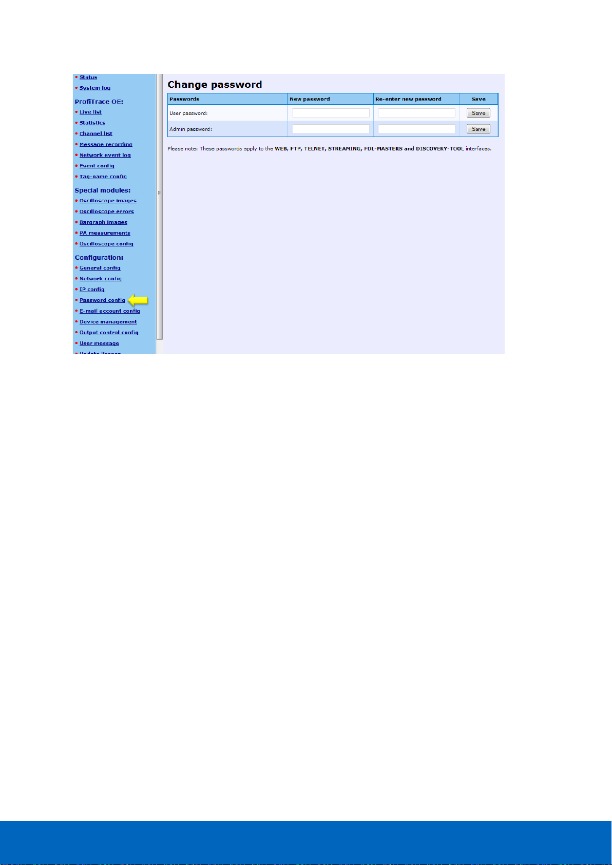
ComBricks User Manual v6.4.0 | January 18| © PROCENTEC 51/219
4.8.2 Password best practice
We encourage you to at least setup the Administrator password if more than 1 person has access to the
network.
• Activate the password(s) immediately after installation or at the office before it is transported to the final
destination.
• Use different passwords for the Administrator and User.
• Never share passwords with anyone.
• Always use strong passwords. Avoid: test, 123456, <your company name>, <your first name>, ComBricks,
PROCENTEC, etc.
• Change passwords immediately if they may have been compromised.
• If passwords must be written down, store it in a secure place and destroy it when it is no longer needed.
• Be careful about where passwords are saved on computers. Some dialog boxes, such as those for remote
access, present an option to save or remember passwords. Selecting this option poses a potential security
threat.
Fig. 34 - Password setup
Page 52

ComBricks User Manual v6.4.0 | January 18| © PROCENTEC 52/219
4.8.3 External protocols
The following login information is required for external protocols, for example for FTP and TELNET.
Any FTP client can be used to setup the FTP connection. ComBricks uses port 21.
If you have not set a password, ComBricks will accept any password during the connection phase. Some FTP
clients require a password, so you can provide any password.
4.8.4 Clearing password(s)
There are 3 ways to restore the password(s) to their default setting:
• Change the passwords with no text written in the text field (Administrator login required).
• Restore to factory default settings in the "Device management" page (Administrator login required).
• Restore to factory default settings with the switch on the front of the Head Station (see Paragraph 6.5).
User: user or admin
Administrator: <your password>
Page 53
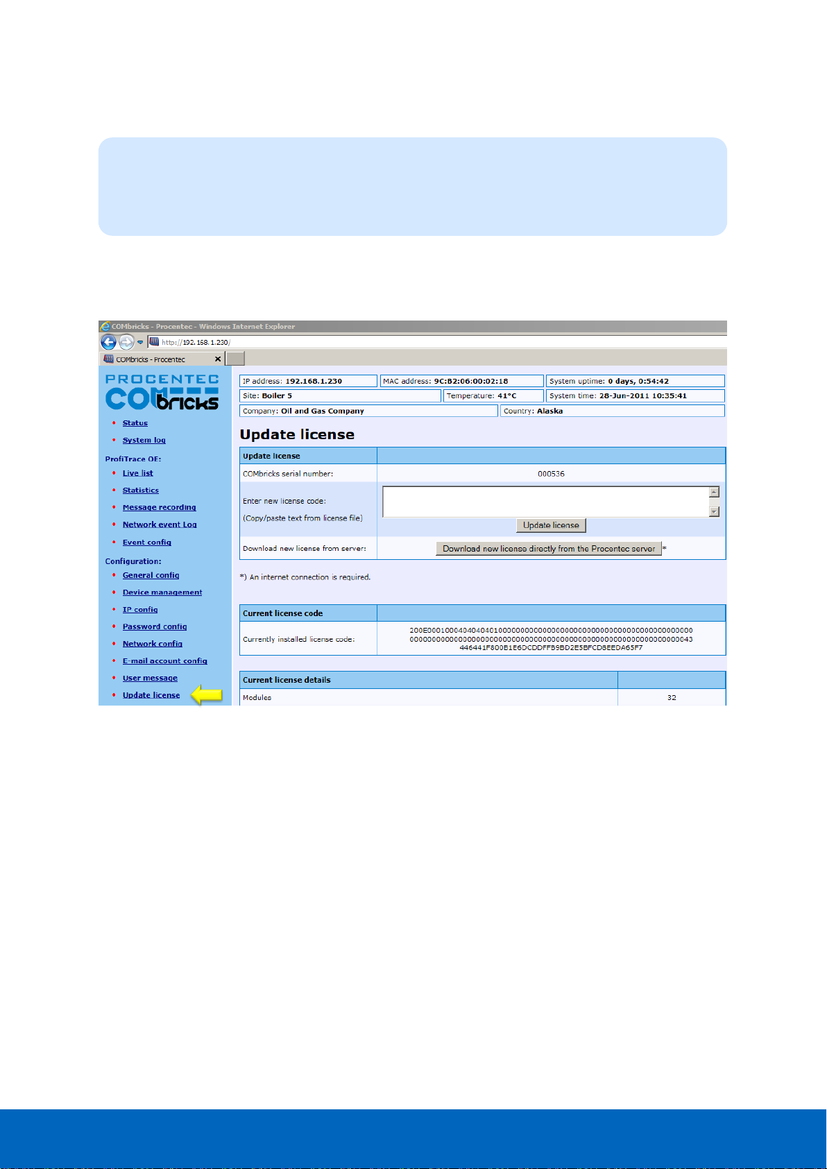
ComBricks User Manual v6.4.0 | January 18| © PROCENTEC 53/219
4.9 License update
In case the user wants to update the license of the Head Station, it can be done here via an internet connection
or copy the content of a license file.
Head Stations: 1A, 1B, 1C
Firmware: V1.254 and higher
Login: Administrator
Fig. 35 - License update
Page 54
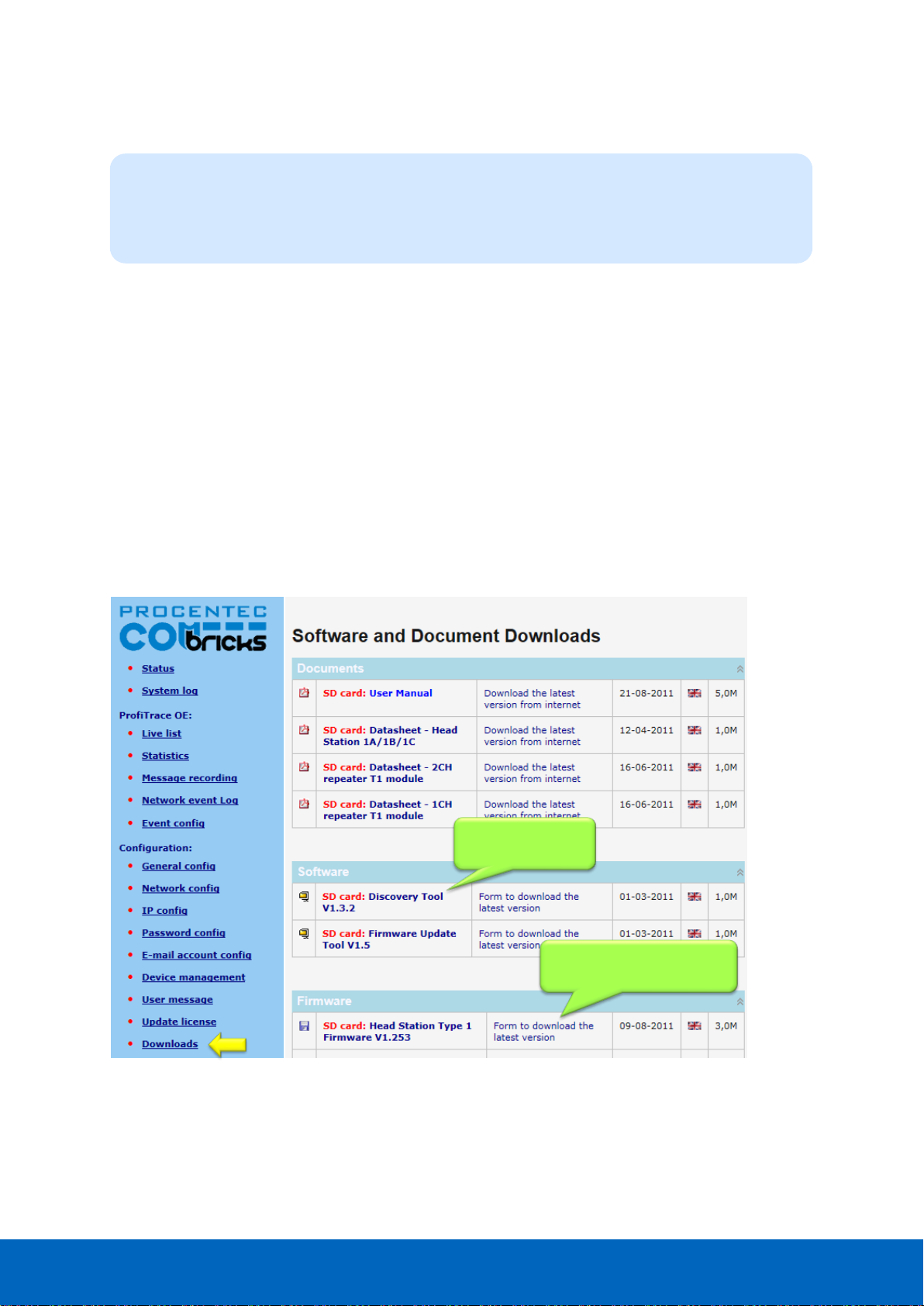
ComBricks User Manual v6.4.0 | January 18| © PROCENTEC 54/219
4.10 Document download page
To provide the user with documentation, firmware and software, the SD card has been provided with a
document download page (see Fig. 36).
• Download the latest version of the document download page from www.procentec.com
• The content of the .ZIP file has to be copied to a directory \DOC on the SD card.
• If the directory does NOT exist, create it and copy the content of the .ZIP file to it.
• Reload the web server to update the information.
• There should be an item called "Downloads" on the bottom of the left menu
It is possible to replace the PROCENTEC download page with a customized version. Replace index.html with
your own version and you can point to directories/files which are located on the SD card. If you are interested
in such activities, we recommend you to inspect the structure of the PROCENTEC index.html first.
Head Stations: 1A, 1B, 1C
Firmware: V1.254 and higher
Login: User or administrator
Link to download
from SD card
Link to download the latest
version from Internet
Fig. 36 - Software and document downloads
Page 55
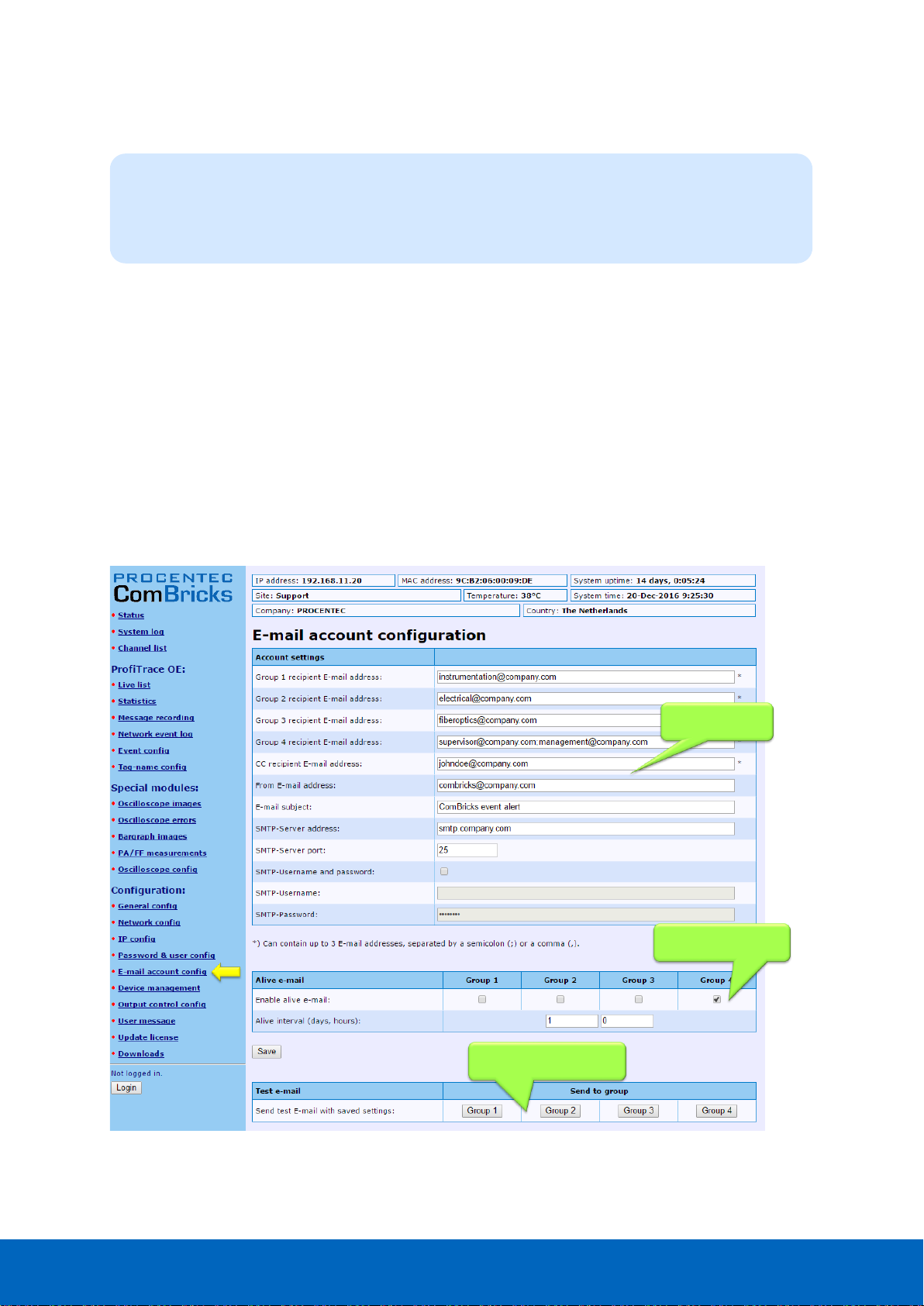
ComBricks User Manual v6.4.0 | January 18| © PROCENTEC 55/219
4.11 Email account config
The email account information has to be entered if the user wants to have ComBricks signal events by email.
The required information is generally the same as any other email related setup (see Fig. 37).
Setting up the email server parameters is not enough.
The events that generate the emails have to be setup
in the ‘Event config’ menu (see Paragraph 5.4).
The SMTP server has to support unencrypted connections, because the current ComBricks firmware
does NOT support encrypted connections such as SSL/TLS. The DNS address (IP config menu) has to
be modified according to the DNS addresses of your internet provider.
Since Head Station version v1.293 you can setup multiple email groups. Each group can receive emails
triggered by different events, which can be set up in ‘Event config’ in paragraph 5.4.
The server parameters have to comply with the email server parameters listed in Table 2.
E-mail server
parameters
Daily test email
enabled
Direct testing of server
settings, per group
Head Stations: 1A, 1B, 1C
Firmware: V1.253 and higher (email groups since v1.293)
Login: Administrator
Fig. 37 - Email configuration
Page 56

ComBricks User Manual v6.4.0 | January 18| © PROCENTEC 56/219
Table 2 - Email server parameters
Server parameters
Mandatory
Additional information
Size
Groups 1 - 4
At least one
group
If you enter multiple addresses (max. 3)
separate them with the ; character.
200
Cc
Optional
If you enter multiple addresses (max. 3)
separate them with the ; character.
200
From
Yes
Depending on the email server you are using,
this has to be an existing email address.
100
Subject
Optional
Can be anything you want it to be.
100
SMTP server
Yes
Has to be setup according to the requirements
of the email server.
100
SMTP server port
Yes
Standard value for most servers has already
been entered, but has to be setup according to
the requirements of the email server.
User name
Optional
A User name can be entered if the SMTP server
requires it. Click on "SMTP-Username and
password" first.
50
Password
Optional
A password can be entered if the SMTP server
requires it. Click on "SMTP-Username and
password" first.
50
When you have filled in all server parameters, click on "Save". The settings can be tested by clicking on "Send
test email with saved settings".
Save the settings first before sending the test email!
It might take a couple of minutes before the test email has been received by the recipient.
If the test-email has not been received, please check if it has been blocked by a Spam filter.
4.11.1 Alive email
ComBricks can send a periodic alive-email to the recipient group(s) entered in the Group: field. If no events are
triggered for a longer period, ComBricks will not send emails. This also happens when ComBricks has no
connection to the mail server for some reason. The alive email is an automated check to see that the
connection is still active.
ComBricks can auto-send an email with adjustable interval of anything between one hour and 365 days.
Page 57
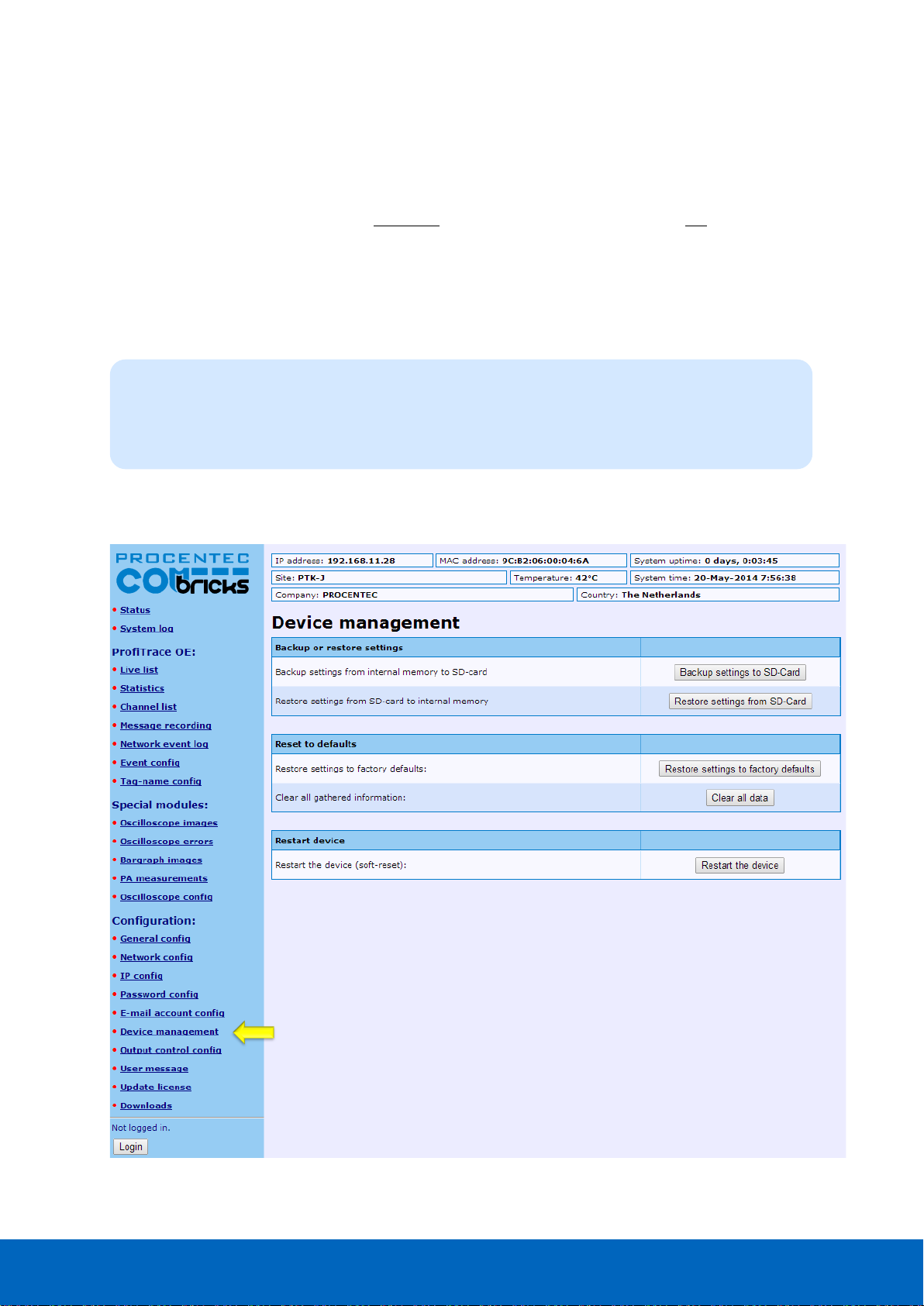
ComBricks User Manual v6.4.0 | January 18| © PROCENTEC 57/219
4.11.2 Email Troubleshooting
• Check if ComBricks has access to the internet. You can easily test this by going to the Download page in the
ComBricks menu and download a datasheet from the web.
• Compare the DNS settings with the requirements of the email server you are using.
• Make sure your email server supports unsecured connections (secured connections are not possible).
• Check the email settings and generate the test email. Start with only 1 email address.
• If the test email works, please check that your events have been correctly enabled and an event is really
triggered.
4.12 Device Management
The Device Management page allows the user to perform backup, restore and restart actions for the
ComBricks. For some actions Administrator login is required.
Head Stations: 1A, 1B, 1C
Firmware: V1.253 and higher
Login: Administrator
Page 58

ComBricks User Manual v6.4.0 | January 18| © PROCENTEC 58/219
4.12.1 Backup settings to SD-Card
When this button is clicked, all customizable settings of each individual network and of the Head Station are
saved to SD-Card. These settings include Message recording settings, name and identification tags, scope
settings and IP and email settings.
This feature allows a quick and easy replacement of a defective Head Station. If a Head Station needs to be
replaced, and settings have been backed up on SD card, remove the SD card from the slot and place it in the
new Head Station. Then continue with paragraph 4.12.2.
4.12.2 Restore settings from SD-Card
When you replaced the SD card with information from another Head Station, click ‘Restore settings from SD
Card’ to load all information into the new Head Station. Then click ‘OK’ on the confirmation window.
Settings are loaded and activated instantly; no restart is required.
4.12.3 Restore settings to factory defaults
This button clears all entered information and restores the ComBricks Head Station to the default factory
values. The new IP address is 192.168.1.254
4.12.4 Clear all data
When a ComBricks set has been installed and is ready for normal operation, it may have recorded several
events which are not ‘real’ faults. This can happen during wiring or commissioning phase. Press ‘Clear all data’
to start the ComBricks logging and recording functions with a clear memory. Then click ‘OK’ on the
confirmation window.
IMPORTANT NOTE: This will also clear all Message Recording files!
4.12.5 Restart the device
To restart the device, for example to let it read new dipswitch settings or DNS server settings, click the ‘Restart
the device’ button. Then click ‘OK’ on the confirmation window.
This ‘soft’-reset will not affect PROFIBUS communication on the repeater modules; the repeater functionality
will continue during reset.
Page 59

ComBricks User Manual v6.4.0 | January 18| © PROCENTEC 59/219
5 ProfiTrace OE
ProfiTrace OE (Over Ethernet) is a web based version of ProfiTrace. It offers the basic functionality of regular
ProfiTrace, like; Live List, Statistics and Message recording. ProfiTrace OE is available on the Head Stations 1B
and 1C.
5.1 Live List
The Live List is a matrix that continuously lists all the available devices. It is directly visible which devices are
‘troublemakers’. With different background colors, the status of the devices is displayed (see Fig. 38):
• Green: Device is in Data Exchange
• Yellow: Device is lost (the time-out is adjustable, see paragraph 4.5)
• Red: Parameter fault
• Purple: Configuration fault
• No color: On the bus but not in Data Exchange
The Live List can also generate the product name of the devices when a diagnostic message is captured
(synchronized with the GSD library).
The button ‘Display Legend’ pops up a window explaining all colours in more detail.
“Colours make it easy…”
Page 60

ComBricks User Manual v6.4.0 | January 18| © PROCENTEC 60/219
5.1.1 Updating the GSD file library
The procedure below describes how to update the GSD file information in ComBricks so that all devices in the
Live List have a full model name.
STEP 1: Start regular ProfiTrace (2.6 or higher, no license required).
STEP 2: Copy all GSD files you require into the ProfiTrace GSD directory. This is usually
".....\ProfiTrace_Vx_x_x\GSD".
STEP 3: Create a ComBricks GSD library (Settings > Create ComBricks GSD library).
A question is asked if you want to re-scan the GSD files. Select YES followed by (re)Scan
GSDs. Click ‘Close’ when the process has been finalized.
STEP 4: A pop-up box allows us to select the destination folder.
Select a (temporary) destination folder for the file GSD.BIN, for example the Windows
desktop.)
STEP 5: GSD.BIN has to be copied to the SD card of the ComBricks. You can do this by inserting it in
your PC or FTP (admin account).
STEP 6: After inserting the SD card back into the Head Station or closing the FTP session, the GSD
information is directly available in the Live List. Paragraph 18.1 describes a method of
testing the updated GSD.BIN.
Similar Live List as
ProfiTrace 2
Monitoring 4
networks
Monitoring 4
networks
Monitoring 4
networks
Monitoring 4
networks
Fig. 38 - ProfiTrace Live List
Page 61

ComBricks User Manual v6.4.0 | January 18| © PROCENTEC 61/219
5.2 Statistics
The statistics matrix is a powerful feature of the analyzer. This field can really indicate what the condition of
the installation is. It displays all the important information that a user, especially a maintenance technician, is
really interested in (see Fig. 39):
• Retry messages
• Fall-outs (losts)
• Diagnostic messages
• Location of the connected devices, etc.
Paragraph 5.9 describes the statistics and when they occur.
Because of this feature, the user does not have to inspect messages or do difficult operations to ensure the
quality of the installation.
If the statistics do NOT show deviations, the installation appears to be running correctly.
Here it stops for the technician who is only interested in a quick feedback. The advanced technician can
proceed with a message recording and an inspection of the signal quality.
Similar Statistics as
ProfiTrace 2
Monitoring 4
networks
Monitoring 4
networks
Monitoring 4
networks
Monitoring 4
networks
Fig. 39 - ProfiTrace OE Statistics
“Click and go…”
Page 62
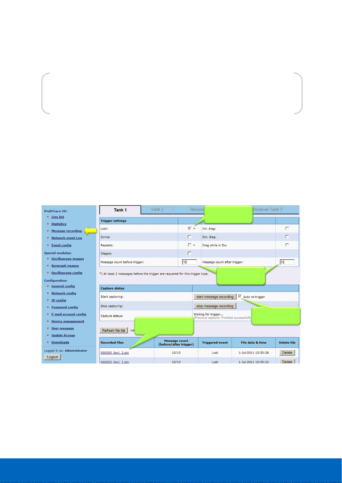
ComBricks User Manual v6.4.0 | January 18| © PROCENTEC 62/219
5.3 Message recording
The message recording in ProfiTrace OE follows a different strategy than ProfiTrace 2. Within ProfiTrace 2, the
user needs to setup the message recording first and is he responsible to start it himself.
Because ComBricks is a unit for permanent monitoring, it automatically starts a message recording when an
event has been detected. The following event automatically starts a message recording again.
When the unit is purchased or reset, it is automatically triggered on the statistic "Lost". This works directly after
startup. The user can change the settings during operation (see Fig. 40).
The recorded files can be opened with an offline ProfiTrace 2 (no license required).
Trigger settings.
Lost is default
Recording rangeRecording range
Automatic
re-triggering
Already recorded files
from network 1
Fig. 40 - Setup recording trigger
“Catch it all…”
Page 63

ComBricks User Manual v6.4.0 | January 18| © PROCENTEC 63/219
The automatic triggering can generate 1000 .PTC files per network4. After 1000 files have been
generated, the follow-up event will delete the oldest file and replace it with the latest event. This
system secures the storage space of the SD card.
.PTC files can be opened with ProfiTrace 2.5.3 and higher (offline and no licenses required).
The file name contains the MAC address of the Head Station, the network number and the file number (0-999).
5.4 Event configuration
For generating emails and entries in the network log, the event configuration has to be set for each network.
Fig. 41 shows an example with multiple event options. Since Head Station version v1.293 it is possible to send
emails of individual events to specific email groups (see also paragraph 4.11). This is useful for large
organizations with different maintenance teams or user groups.
Paragraph 5.9 describes the events and when they occur.
To reduce an unwanted overload of emails or log entries, the events can be set to Off, Once or Interval.
4
This feature is available in firmware version 1.264 and higher.
Every network can be
configured individually
Event notification: by
email and/or log
Enable email for each
event per group
Event notification: by
email and/or log
Multiple options
for an event:
- Off
- Once
- Interval
Fig. 41 - Event configuration
Page 64
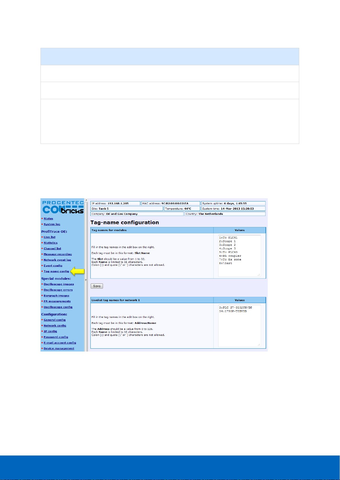
ComBricks User Manual v6.4.0 | January 18| © PROCENTEC 64/219
Even parameter
Description
Retrigger required
Off
No event generation.
Once
Event will be generated once (1-shot).
Yes
Interval
Event will be generated once within the customized
interval time. After the interval time the event is
automatically retriggered to be generated in the next
interval. If no trigger was captured in the new interval
period, no event will be generated.
No
The interval time can be customized between 1 minute and 365 days.
5.5 Tag name configuration
Every ComBricks module and every station in every network can be tagged with a name.
Fig. 42 - Tag name configuration screen
The first block of tag names is used to assign tags to the ComBricks modules.
Each tag must have the format slot:name, where slot is the slot number. The tag names are limited to 16
characters. The Colon (:) and quote (‘ or “) characters cannot be used.
The second to the fifth block of tag names are used to assign tags to individual stations in each network.
Tag names are stored on the SD card. Use the ‘Backup’ and ‘Restore’ feature to reload the names if you change
the Head Station, see paragraph 4.12.
The tag names are visible in the Channel List page if you hover the mouse pointer over a module or station
address. It is also possible to show the tag names in the Live List:
Page 65

ComBricks User Manual v6.4.0 | January 18| © PROCENTEC 65/219
Tag names of modules are also displayed in drop-down references to modules and in tables on the following
pages:
• Oscilloscope Images
• Oscilloscope Error Images
• Oscilloscope configuration
• Bar Graphs
• PA measurements
• Network Configuration
• Output Control configuration
Page 66
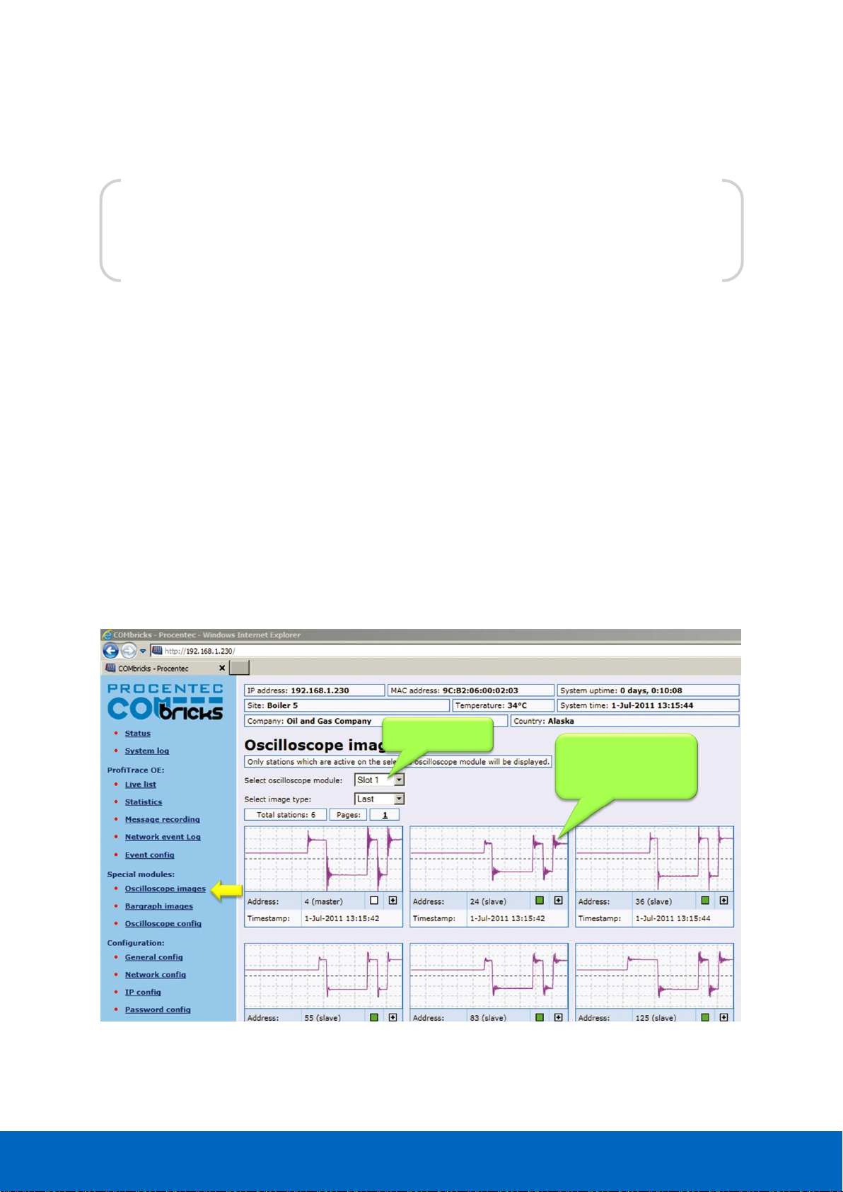
ComBricks User Manual v6.4.0 | January 18| © PROCENTEC 66/219
5.6 Oscilloscope images
SCOPE repeater modules have an integrated oscilloscope to measure the signal quality of the telegrams. The
oscilloscope has an interface with the web server to display the signals from the devices which are connected
to its channel. After opening the web page, all oscilloscope signals are displayed and updated live.
The SCOPE repeater is the most easy to use PROFIBUS oscilloscope available:
• You do NOT have to touch the installation
• Works automatically, even images saves to SD card (since firmware version 1.286)
• Oscilloscope data is never mistaken with the wrong segment
• No probe wiring
• No spur lines
By clicking on the oscilloscope waveform of a device, the oscilloscope triggers on the respective device and
displays its signals in a new page.
The SCOPE repeater is only able to do differential measurements.
Oscilloscope images of
all connected devices
behind this SCOPE
repeater
Selected slots
Fig. 43 - Oscilloscope images from all devices
“The easiest PROFIBUS oscilloscope ever…”
Page 67
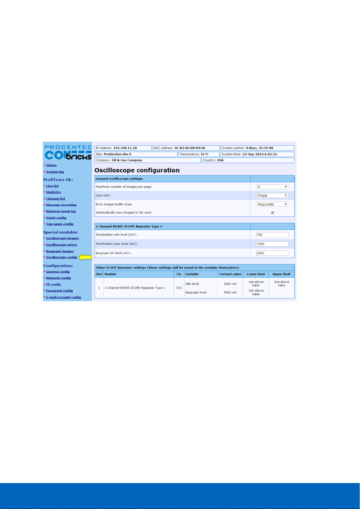
ComBricks User Manual v6.4.0 | January 18| © PROCENTEC 67/219
5.6.1 Oscilloscope Configuration
The following changes can be made to the Oscilloscope pages:
• Number of images per page
• Line color
• Error images buffer type
• Auto-save images to SD –card
• Termination min/max level
• Bargraph OK level
• For DP-IS (Ex) and PA modules: Specific trigger levels
Click the Oscilloscope Config in the left menu to change these settings.
Fig. 44 - Oscilloscope configuration
5.6.1.1 Max number of images per page
You can change the number of scope images per page. If you want a larger overview of all stations, choose a
larger number. But keep in mind that one image is updated every second (by default, can be changed in
General Settings). So if you have many nodes, it will take a long time to refresh all the images on the page.
5.6.1.2 Line Color
You can change the line color of the scope. Default is purple for clear contrast when printing the page.
5.6.1.3 Error images buffer type
The error images buffer type can be set to Ring Buffer (default) or ‘ Stop when full’. The ring buffer keeps
recording new images to memory, so you can keep refreshing the page for new error messages. The module
keeps a maximum of 16 latest images in memory. The ‘ Stop when full’ mode only logs the first 16 error images
and 16 into memory, and then stops recording.
5.6.1.4 Auto save images to SD card
This feature (available since firmware version v1.286) makes sure the images are periodically saved to the SD
card, so they are not lost in the event of a power-cycle.
Every 15 minutes the following images are saved automatically if they need to be updated:
Page 68
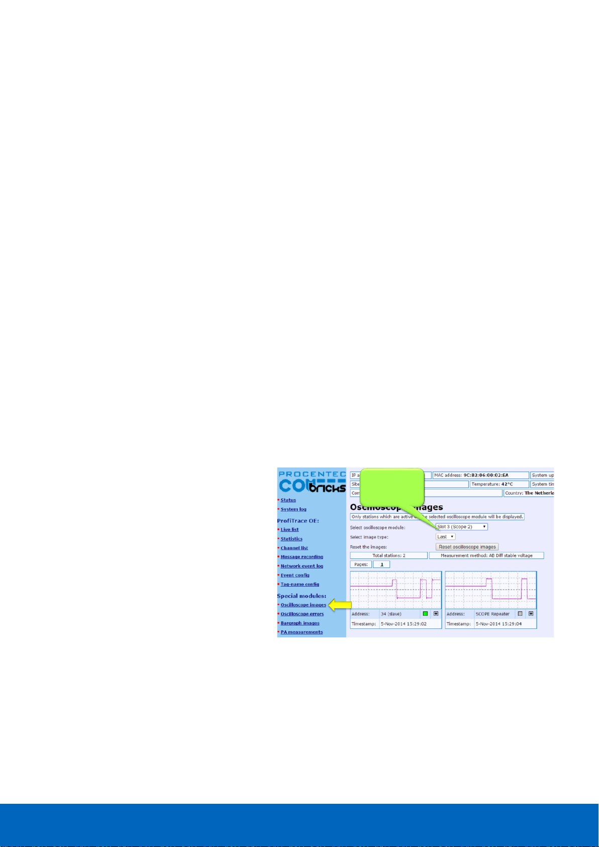
ComBricks User Manual v6.4.0 | January 18| © PROCENTEC 68/219
• The Min and Max image types per address per module (so a maximum of 2 x 127 per module)
• Bar Graph (one per module)
• Error images (maximum 16 per module)
If all images have been saved to SD card, one entry per module will be added to the system log. This makes it
possible to check if an image has been saved to SD card after a certain event or error.
The first 16 error images are saved to SD card. After this, the Scope module saves another 16 images in
memory. These can be saved manually to SD card by clicking on ‘ Refresh scope images’ in the Oscilloscope
Images page of the corresponding module.
The images are saved in an XML-based vector format .svg which can be viewed in any compatible browser.
Recommended is Internet Explorer 9 or higher. You can also find freeware SVG file viewers in the Internet.
The images are located in the following folder on the SD card: /mmc$/graphs/
You can access the path via any FTP-capable browser, FTP program or simply put the SD-card in your PC (but
make sure the SD card is write-protected when you insert it in the PC). See paragraph 4.8.3 for more
information.
5.6.1.5 Termination level
For regular Scope Repeater modules you can change the Termination min and max trigger level. This changes
the idle voltage limit. Normally the idle voltage should be around 1V. You can change the sensitivity of this
measurement. If the level is exceeded, the red LED ‘ TERM’ will illuminate.
5.6.1.6 Bargraph OK limit
You can change the red line in the Bar Graph which is the trigger point for the red ‘MIN’ LED on the Scope
module. If the installation is very stable with high amplitudes of 4V and more, you could consider raising the
Bargraph OK limit to 3V for example. Or if you have problems with a certain slave which cannot get a higher
amplitude than 2.5V, you can lower the limit to 2V.
5.6.2 Oscilloscope Images
The oscilloscope modules can be viewed by
clicking on the ‘Oscilloscope images’ menu on
the left of the webserver screen.
If more than one module with Scope
functionality has been installed in the
ComBricks, you can select that module in the
drop-down list and see Scope images from
devices connected to that module.
The Image type lets you view the Last, Min or
Max scope image. The Min and Max are the
lowest and the highest measured amplitudes.
Fig. 45 - Oscilloscope images
When the ‘Min’ value drops below the configured ‘Bargraph OK limit’ (default 2.5V) the red LED ‘Min’ will
illuminate on the Scope module. To reset the ‘Min’ and ‘Max’ values simply click the ‘Reset oscilloscope images’
button.
5.6.3 Oscilloscope errors
Whenever an illegal message is seen by ComBricks, and the message occurred on a module with a Scope, you
will be able to find the signal of that illegal message. This is very useful for troubleshooting, because it captures
the moment of a failure. This makes it easy to prove EMC or other cable problems.
Select ComBricks
module and image
type
Page 69

ComBricks User Manual v6.4.0 | January 18| © PROCENTEC 69/219
Fig. 46 - Oscilloscope error images
You can view the Scope Error images per slot. The Head Station can hold 16 error images per slot in memory,
and if there are more than 16 error images you can click ‘Refresh error images’ to load these.
To clear all error messages from memory click ‘Reset scope error images’.
Select ComBricks
module
Page 70
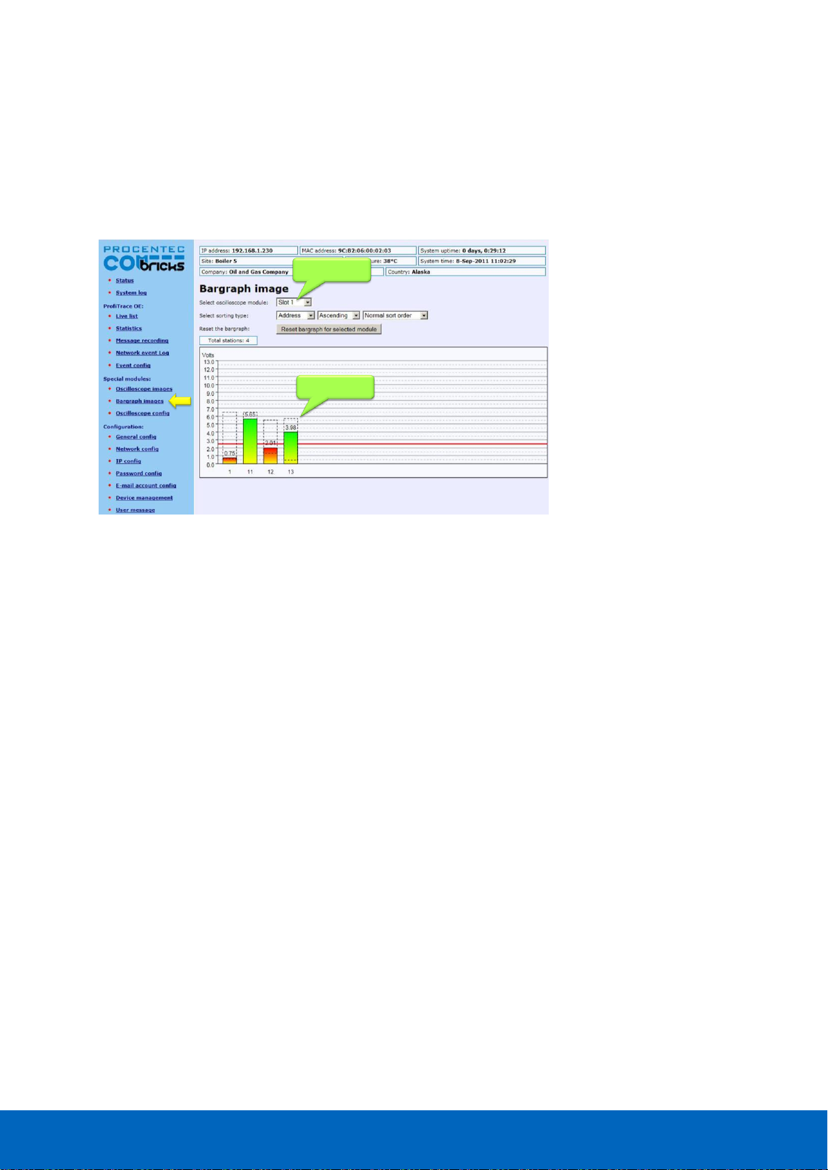
ComBricks User Manual v6.4.0 | January 18| © PROCENTEC 70/219
5.7 Bar graph
The Bar graph illustrates the average signal strength from all available connected devices behind a specific
SCOPE repeater. It is a helpful utility to get an impression of the overall signal quality of the network.
The average amplitude should be around 5 V. When there are bus problems the Bar graph will display different
Voltage levels and the color of the bars will change.
5.8 Streaming with ProfiTrace 2
Streaming with ProfiTrace 2 is a feature that allows the user to use the ProfiTrace 2 software and create a
scenario as if a ProfiCore is connected to the PC. ProfiTrace 2 is a software tool used by thousands of engineers
worldwide, so there is much experience with this tool. A license for ProfiTrace 2 is NOT required!
Streaming with ProfiTrace 2 only works under the following circumstances and settings:
Only Head Stations Type 1B or 1C with firmware V1.253 or higher
• Max. 1.5 Mbps (PROFIBUS)
• Clean TCP/IP connection
• ProfiTrace 2.6.0 or higher
• Only 1 ComBricks connection
After successfully installing ProfiTrace 2, you can find a 'ProfiTrace v2.x for ComBricks' in the start menu of
Windows (see Fig. 48).
This is the standard ProfiTrace2.exe, but with an additional parameter; ProfiTrace2.exe" -_CBMODE_
After Starting 'ProfiTrace V2.x for ComBricks' ProfiTrace will initially look very similar to the regular version, but
now with a reduced number of program option tabs offered near top of screen. The ScopeWare, Bargraph,
Topology, ProfiCaptain and other tabs/menus are missing to the right of the single ProfiTrace tab (see Fig. 48).
Selected module
Signal quality
Fig. 47 - Bar graph
Page 71
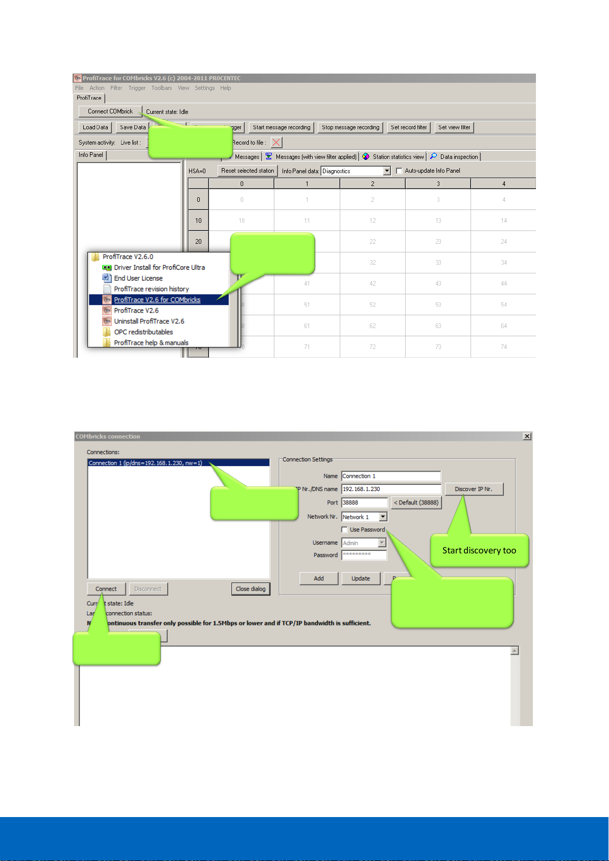
ComBricks User Manual v6.4.0 | January 18| © PROCENTEC 71/219
After clicking on the 'Connect ComBricks' button, a mid-screen dialogue window is displayed which is used to
setup the connection with ComBricks (see Fig. 49).
2.Connect to a
COMbricks unit
1. Start this
shortcut from the
Start Menu
Available
connections
Start connection
Start discovery tool
Important parameters!
(network, user and
password)
Fig. 48 - Starting ProfiTrace 2 for ComBricks
Fig. 49 - Setting up the connection
Page 72

ComBricks User Manual v6.4.0 | January 18| © PROCENTEC 72/219
Important parameters for the connection and the streaming process:
• IP number
• User type and password
• Network number
If one of the connection parameters is incorrect, the connection will
not be established or no data is streamed. It is recommended
to start the discovery tool to verify the IP connection.
Multiple connection instances can be saved and loaded each with their own connection parameters.
ComBricks itself can handle 1 streaming connection, but on the PC
multiple ProfiTrace instances can be opened that simultaneously
communicate with different ComBricks units.
Page 73

ComBricks User Manual v6.4.0 | January 18| © PROCENTEC 73/219
5.9 Summary of Statistics and Events
This paragraph contains a description of the items listed in the statistics and/or events.
Statistics
Description
Critical
Lost
How many times a device in data exchange fails to respond after
the maximum retries have been reached. Lost is retriggered
when the device recovers back to data exchange and fails to
respond again.
• Live List will indicate a yellow colored address (after time-
out).
• When the device was already lost after the activation of
ProfiTrace Lost will not be updated. Only Syncs will indicate
the problem.
YES
Syncs
Attempts of the master to contact a device for the first time or
establish a communication relationship. This occurs in most cases
after station lost, device unavailability or startup of the master. In
the statistics view this values adds up relatively quick.
• Some DCS systems read diagnostics all the time with Syncs
ON.
• - Live List could indicate a yellow colored address.
YES
(in most
cases)
Repeats Total
Attempt of the master to get a response from an unanswered
telegram. The response did not come or has content errors. The
maximum amount of repeats a master attempts can be
customized in the master.
• When the retries have reached the limit, the master goes to
the Syncs state
YES
Repeats Max
(worst sequence)
This value represents the highest amount of retries that were
attempted on this specific device in one cycle.
• This value will never get higher than the retry value that has
been setup in the master.
YES
Illegal Responses
The response to a master request telegram contains framing
errors (parity error, wrong FCS, SD error, etc). This mostly
happens with EMC and cabling problems.
• When this statistic adds up relatively quick, it could also be a
double device address.
YES
Internal Diag
Negative responses at the lowest telegram level (Layer 2: FDL)
and are rare. In the telegram recording you will see SD1
telegrams with for example an RS (Reject Service) or RR (Reject
Resources).
Examples of situations where this occurs:
• DP-V1 connections to DP-V0 devices.
• Watchdog has run out on a DP device and the master sends a
Data Exchange output telegram.
• Non-certified DP devices that do not support a specific
service/command or cannot handle a command in time.
NO
Page 74

ComBricks User Manual v6.4.0 | January 18| © PROCENTEC 74/219
Statistics
Description
Critical
External Diag
All responses from Get Diagnostics requests from all masters.
NO
Diag while in DX
Only responses to Get Diagnostics requests from the master that
controls this slave (primary class 1 master).
• When the first 2 bytes of the diagnostic content contains a 08
0C or 08 04, a red indicator blinks in the left corner of the
device in the Live List (critical content).
YES
(in most
cases)
Master lost
One of the masters is not active after getting the token; it is not
responding anymore. Note that this also happens when a Class 2
DP-V1 master is disabled.
YES
(in most
cases)
Baudrate change
The detected baudrate of the PROFIBUS network has been
changed.
YES (in most
cases)
Low/High signal
(Bargraph)
At least one station has a too low (in DP and PA networks) or too
high (in PA networks only) amplitude.
YES
Redundancy Failure
One of the redundant cables has failed.
NO
PA/FF signal and levels
PA or FF values such as jitter, DC voltage or DC noise out of
range.
YES
High/Low signal Fiber
Optic
Fiber Optic signal is out of range.
YES
Ring Failure (fiber
optic)
Fiber Optic ring is broken.
YES
Page 75

ComBricks User Manual v6.4.0 | January 18| © PROCENTEC 75/219
6 Head Station 1A/1B/1C
The Head Station is the primary element of ComBricks and has to be inserted in the most left
slot of the fixed backplane socket. It schedules the interaction between all modules and
provides data storage and an Ethernet interface for the user.
6.1 Overview
Type 1A is the basic model and ALL Head Stations are hardware technically identical with type
1A.
Type 1B and 1C are enhanced types that contain a ProfiTrace core and advanced web server for
permanent remote maintenance of the PROFIBUS installation over Ethernet (hardware is
identical as a type 1A).
• Type 1A: NO monitoring capabilities, no streaming, no OPC
• Type 1B: Monitors 1 PROFIBUS network + ProfiTrace 2 streaming + OPC (since June 2013)
• Type 1C: Monitors 4 PROFIBUS networks + ProfiTrace 2 streaming + OPC
For the monitoring with ProfiTrace OE, repeater modules or slave modules are required to provide PROFIBUS
telegrams on the backplane network.
Head Station type 1B and 1C are able to stream live data directly in the ProfiTrace 2 software package over
Ethernet. ProfiTrace 2 will run with full monitoring functionality and the user can benefit from its features.
The Head Station provides power to all modules through its redundant power supply.
Table 3 - Head Station comparison
Head Station 1C
(101-20011C)
Head Station 1B
(101-20011B)
Head Station 1A
(101-20011A)
Backplane networks
(for repeater modules)
4 4 4
Web server
YES
YES
YES
CommDTM / Class 2 master
YES
YES
YES
SNMP
YES
YES
YES
ProfiTrace OE networks
(for monitoring)
4
(ALL networks)
1
(network 1)
-
Oscilloscope features
YES
YES
-
ProfiTrace 2 live streaming
YES
YES
-
OPC
YES
YES
-
Page 76

ComBricks User Manual v6.4.0 | January 18| © PROCENTEC 76/219
6.2 Relay contact
With the relay contact it is possible to react on an event (retries, lost, bus voltage too low, etc). It is also
possible to control the relay manual or on a timer. Refer to Paragraph 4.7 for details. The relay is capable of
switching 0.5 A - 24 VAC.
6.3 SD card
The SD card is used to store ProfiTrace file recording data, logs, the GSD info file and backup settings.
By default a 1 GB SD card is supplied together with the Head Station, but it can be exchanged by an SD card
with a maximum size of 32 GB.
The SD card is addressable directly with an FTP client. In the FTP software the SD card has a drive letter with a
directory structure, on which files can be read and written from and to the SD card. When the password is set
in the web server, this same password has to be used by the FTP software to establish a connection.
6.3.1 Inserting/replacing the SD card
The socket is located on the front plate of the Head Station.
To remove the SD card, gently press it inwards. The SD card is unlocked and released from the socket.
With insertion, just insert the SD card in the socket and press it inwards. The SD card socket has a polarity to
make sure it is not inserted backwards.
The SD card is hot swappable, but there is a risk that
monitoring data is lost when the system wants to write
at exactly the same time as the removal or insertion.
Page 77

ComBricks User Manual v6.4.0 | January 18| © PROCENTEC 77/219
6.3.2 Life cycle of the SD card
The life of a SD card depends on the following factors:
• Number of read and write operations
• Ambient temperature
At an ambient temperature of up to 60 °C the SD card has a service life of 10-years at maximum 100000
write/delete sequences.
If the maximum number of read and write operations has exceeded the limits, data loss may be possible.
6.3.3 Directories and files
The following directories have been standardized for ComBricks and are in most cases located on the SD card;
Directories
Description
/Busmon
ProfiTrace message recording files
(Head Station type 1B and 1C only)
/Log
Log files
/Doc
Contains the web server download page
(See Paragraph 4.10 on how to set it up)
Files and extensions
Description
Journal.DAT
System file
(Do not delete or remove it)
GSD.BIN
File with GSD information for the Live List.
(Generated with the ProfiTrace 2 software).
See Paragraph 5.1.1 how to generate this file.
SETTINGS.INI
Head Station settings
(IP address, name, location, etc.)
LICxxxxxxx.TXT
License files
.PTC
ProfiTrace OE message recoding files. (located in the "Busmon" directory).
The files can be opened with ProfiTrace V2.5.3 and higher (See Paragraph
5.3 on how to generate PTC files).
.PKG
Firmware files
.CSV
Log files
(located in the "Log" directory)
Page 78

ComBricks User Manual v6.4.0 | January 18| © PROCENTEC 78/219
6.4 Audio jack
Not supported. This connector is removed from hardware versions higher than 1.5.
Page 79

ComBricks User Manual v6.4.0 | January 18| © PROCENTEC 79/219
Normal
menu
(NL)
Special
Menu
(SL)
Wait
key
(L1)
Read settings
from SD card
Tap Down
Hold
up for
5 seconds
Hold up
For 5 seconds
Wait
key
(L2)
Save settings
to SD card
Tap Down/Up
Hold
up for
5 seconds
Wait
key
(L3)
Clear
password
Tap Down/Up
Hold
up for
5 seconds
Wait
key
(L4)
Reset to
factory
defaults
Tap Down/Up
Hold
up for
5 seconds
Wait
key
(L5)
Warm start
Tap Down/Up
Hold
up for
5 seconds
Tap Down/Up
Execution
confirmed
(XC)
Done
Done
Done
Done
Done
Done
Timeout,
or held down
for 5 seconds
6.5 Switch navigation of the Head Station 1A/1B/1C
Description
NL
SL
Normal mode
(starting point)
All LEDs Blinking
L1
RDY Blinking
L2
ETH Blinking
L3
SF Blinking
L4
IOF Blinking
L5
USB Blinking
XC
LED walk through all
the LEDs
Page 80

ComBricks User Manual v6.4.0 | January 18| © PROCENTEC 80/219
6.6 LEDs on the Head Station
In the tables below the LEDs of the Head Stations during normal operation are described. The LED conditions in
firmware update and menu mode are not described here.
RDY - Ready
OFF
Blinking
ON
Starting up X
Run
X
ETH - Ethernet
OFF
Blinking
ON
No Ethernet link established
X
DHCP configuration is pending
X
Ethernet link established
X
SF - System failure on the Head Station
OFF
Blinking
ON
OK X
Backplane voltage too low (under 5,5 VDC) or current draw
to high (above 2,5 A)
Fast
Clock-chip error
(contact your local Distributor or PROCENTEC)
Slow
Internal component or firmware error
(contact your local Distributor or PROCENTEC)
X
Page 81

ComBricks User Manual v6.4.0 | January 18| © PROCENTEC 81/219
IOF - Failure on modules
OFF
Blinking
ON
OK X
High speed module in slot 11-32
X
More than 32 modules found
X
Module NOT identified
X
USB - Mini USB connecting
OFF
Blinking
ON
No USB connection
X
USB connection
X
SD card
OFF
Blinking
ON
No SD card inserted
X
SD card inserted (activity)
X
SD card inserted (no activity)
X
Page 82
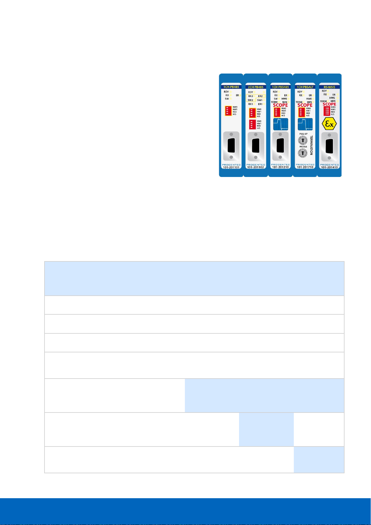
ComBricks User Manual v6.4.0 | January 18| © PROCENTEC 82/219
7 Repeater modules (RS-485)
The standard RS-485 PROFIBUS repeater modules can be a 1 or 2
channel type. Suitable for 12 Mbps with screw terminals,
additional DB9 connector, onboard termination, diagnostic LEDs
and redundancy feature.
The advanced 12 Mbps core of the repeater module is identical as
the ProfiHub and repeater B1; it can be cascaded unlimitedly and
has increased RS-485 strength. It does not have the frustrating
short-circuit bug and the bus communication is constantly
monitored for glitches which are digitally filtered out. Every
channel has on-board switchable termination and is able to drive
31 devices.
The repeater channels are directly connected with the ProfiTrace
OE core in the 1B/1C Head Station. Busmonitor data is directly available in the web server.
10 Repeater modules can be inserted in the backplane. This is independent of the amount of
channels on the repeater modules.
This chapter does not apply to the characteristics of the RS-485-IS Barrier module. It has been listed
for comparison purposes only. For a detailed description of the RS-485-IS Barrier module, refer to
chapter 8.
1CH Repeater
module
(101-201101)
2CH Repeater
module
(101-201102)
1CH SCOPE Rep.
(101-201210)
1CH SALT
repeater module
(101-201710)
1CH RS485-IS
Rep.
(101-201410)
Channels 1 2 1 1
1
Networks 4 4 4 4
4
Redundancy
YES
YES
YES
YES
YES
ProfiTrace
(busmonitor)
YES
YES
YES
YES
YES
Oscilloscope
(bus signals /
bargraph)
NO
NO
YES
YES
YES
EMC and
cable
improving
NO
NO
NO
YES
NO
Intrinsically
safe
NO
NO
NO
NO
YES
See chapter 8
Page 83
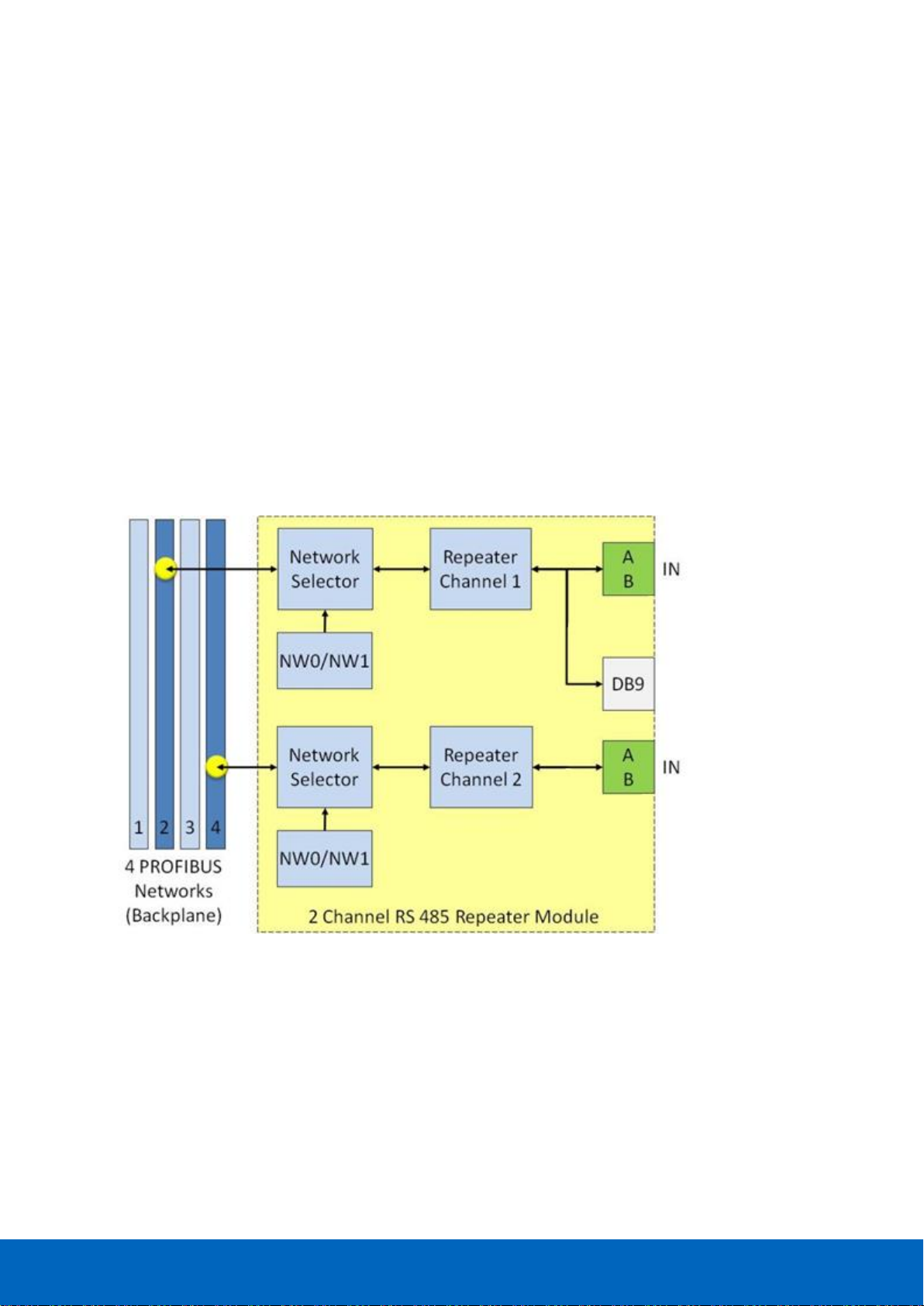
ComBricks User Manual v6.4.0 | January 18| © PROCENTEC 83/219
7.1 Multiple channels per module
Repeater modules contain 1 or 2 channels. Fig. 50 illustrates a 2 channel repeater module. Every channel can
be assigned to a specific backplane network by means of the NW dipswitches or the web server.
NOTICE:
Since March 2014 the 2 Channel modules are fitted with new, more robust screw terminals.
Old modules: The channels (CHx) have 2 screw terminals (IN and OUT, for the bus connection) and a
termination switch.
New modules: The channels have 1 screw terminal and a termination switch. In most cases, the channel
starts here so the termination must be set to ‘ON’. If the channel is not the beginning, use the DB9
connector, see paragraph 3.11.2. Alternatively, use the dual ground clip (supplied with the new models) to
install two cables in one screw terminal, see Fig. 26.
ProfiTrace OE is able to monitor 4 PROFIBUS networks with 2 units of 2 channel repeater modules.
The DB9 connector is connected 1-on-1 to the connectors of channel 1 (see Fig. 50).
Fig. 50 - Multiple channels per module
Page 84
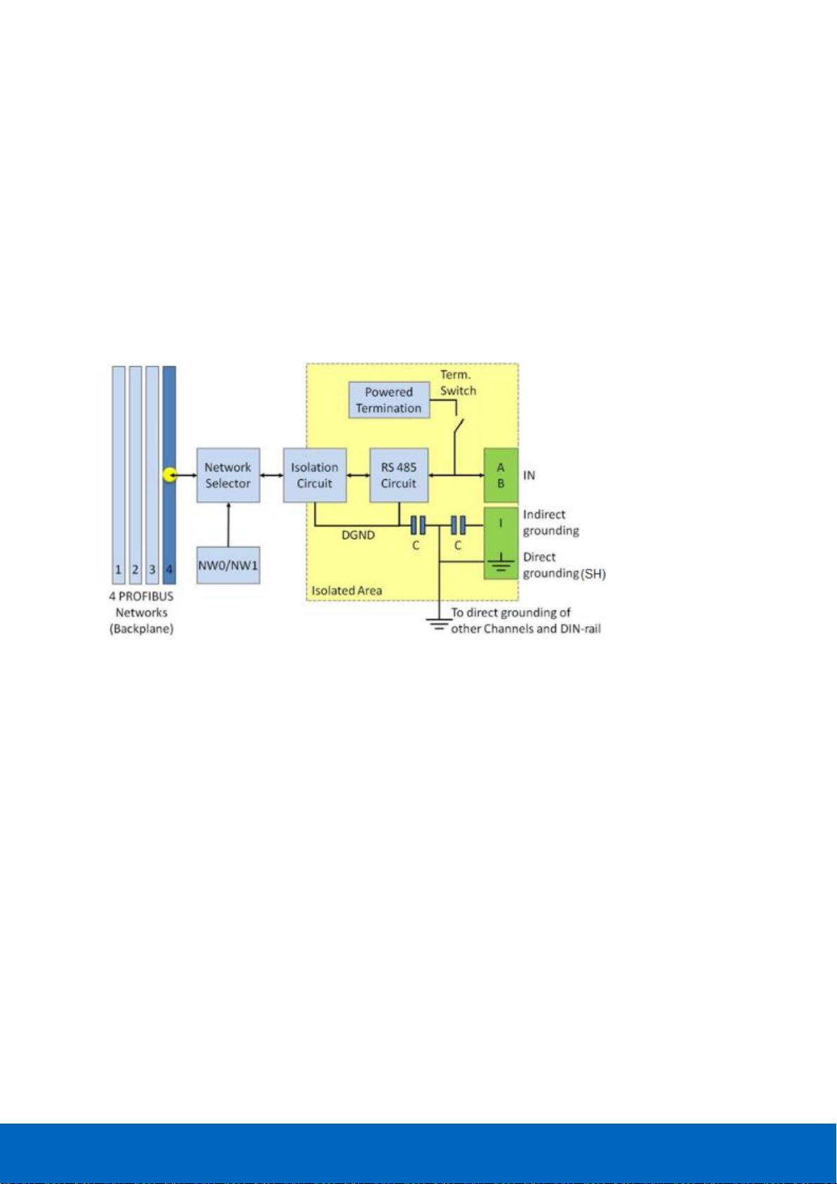
ComBricks User Manual v6.4.0 | January 18| © PROCENTEC 84/219
7.2 Channel structure
Every Channel is electrically isolated and internally connected to one of the transparent PROFIBUS networks on
the backplane (see Fig. 51).
The shielding of the PROFIBUS cable can be directly grounded or indirectly grounded (see Paragraph 7.4).
The termination is switchable and powered by the repeater module. A LED on the front of the module or in the
web server diagnostics indicate the status of the termination switch.
For the old models: When the termination is switched ON, the OUT connector of the specific
channel is disconnected. If it is activated on Channel 1, the DB9 connector is NOT disconnected. In
that case, check for possible termination errors. An extra termination on the connected plug could
jeopardize the communication on the segment. See paragraph 3.11 for examples.
Fig. 51 - Channel structure of the repeater modules
Page 85
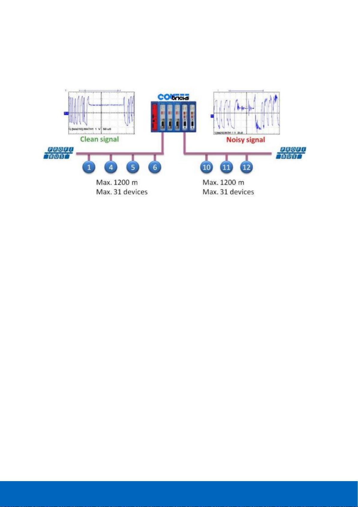
ComBricks User Manual v6.4.0 | January 18| © PROCENTEC 85/219
7.3 EMC barrier
The galvanic isolation and bit recovery circuit in the repeater modules, make the ComBricks perfect to act as an
EMC barrier for sensitive areas.
7.4 Grounding system
There are 3 methods to ground the PROFIBUS cable:
1 Direct grounding
2 Indirect grouning (through a capacitor)
3 Combination of direct and indirect
In most cases it is recommended always to use Direct Grounding with the power supply and the shielding of
the PROFIBUS cables. If you do not want to ground all or some cables to the common ground, the cable
shielding should be connected to pin ‘I’. A capacitor with a parallel high value resistor will separate the 2
potentials (see Fig. 51).
If the Direct Grounding is connected with the Indirect Grounding by mistake, the Direct Grounding “wins”.
7.5 Baudrate detection
It takes less than 10 seconds for a module to detect the baudrate (in practice it will be around 3 seconds). The
detection mechanism is started when telegrams enter the module from the field side (not the backplane). If the
baudrate has been detected, the 'ER' LED will be OFF.
When the baudrate has been detected, the module has to "see" a valid telegram within 50 seconds, otherwise
the module unlocks the baudrate and the 'ER' LED will be ON.
7.6 PROFIBUS DP cable lengths
The length of the PROFIBUS cable connected to the repeater channels should comply with the PROFIBUS DP
cable specifications for RS-485.
Fig. 52 - ComBricks as EMC barrier
Page 86
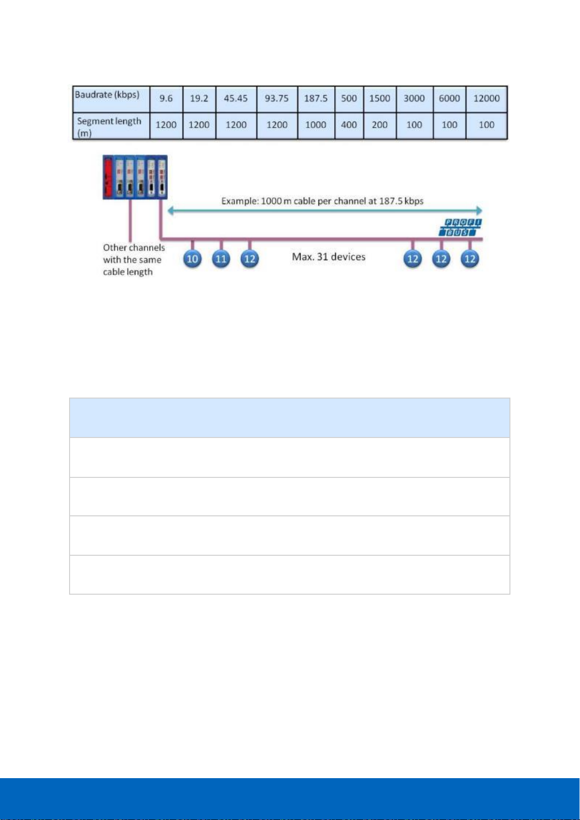
ComBricks User Manual v6.4.0 | January 18| © PROCENTEC 86/219
7.7 PROFIBUS DP cable specifications
The cable should comply with the PROFIBUS DP cable specifications for RS-485.
Table 4 - PROFIBUS DP cable specifications
Parameter
Value
Parameter
Value
Wires
2 (twisted)
Wire diameter
≥ 0.64 mm
Impedance
150 Ohm (3 to 20 MHz)
Wire area
≥ 0.32 mm2
Capacity
≤ 30 pF/m
Shielding resistance
≤ 9.5 Ohm/km
Loop resistance
≤ 110 Ohm/km
Fig. 53 - PROFIBUS DP cable lengths
Page 87

ComBricks User Manual v6.4.0 | January 18| © PROCENTEC 87/219
7.8 PROFIBUS DP cable types
The repeater modules can handle PROFIBUS cable based on multiple protection sheaths with a diameter
between 6 to 12 mm (when the grounding clip is used).
• Robust cable
• Food cable
• Ground cable
• Trailing cable
• Festoon cable
• Fire and heat cable
• Flexible cable
• Shipboard cable
• Rodent protection cable
FRNC cable
Shipboard cable
Festoon cable
Flexible cable
Food cable
Robust cable
Trailing cable
Hybrid cable
Fig. 54 - Supported PROFIBUS cable types
Page 88
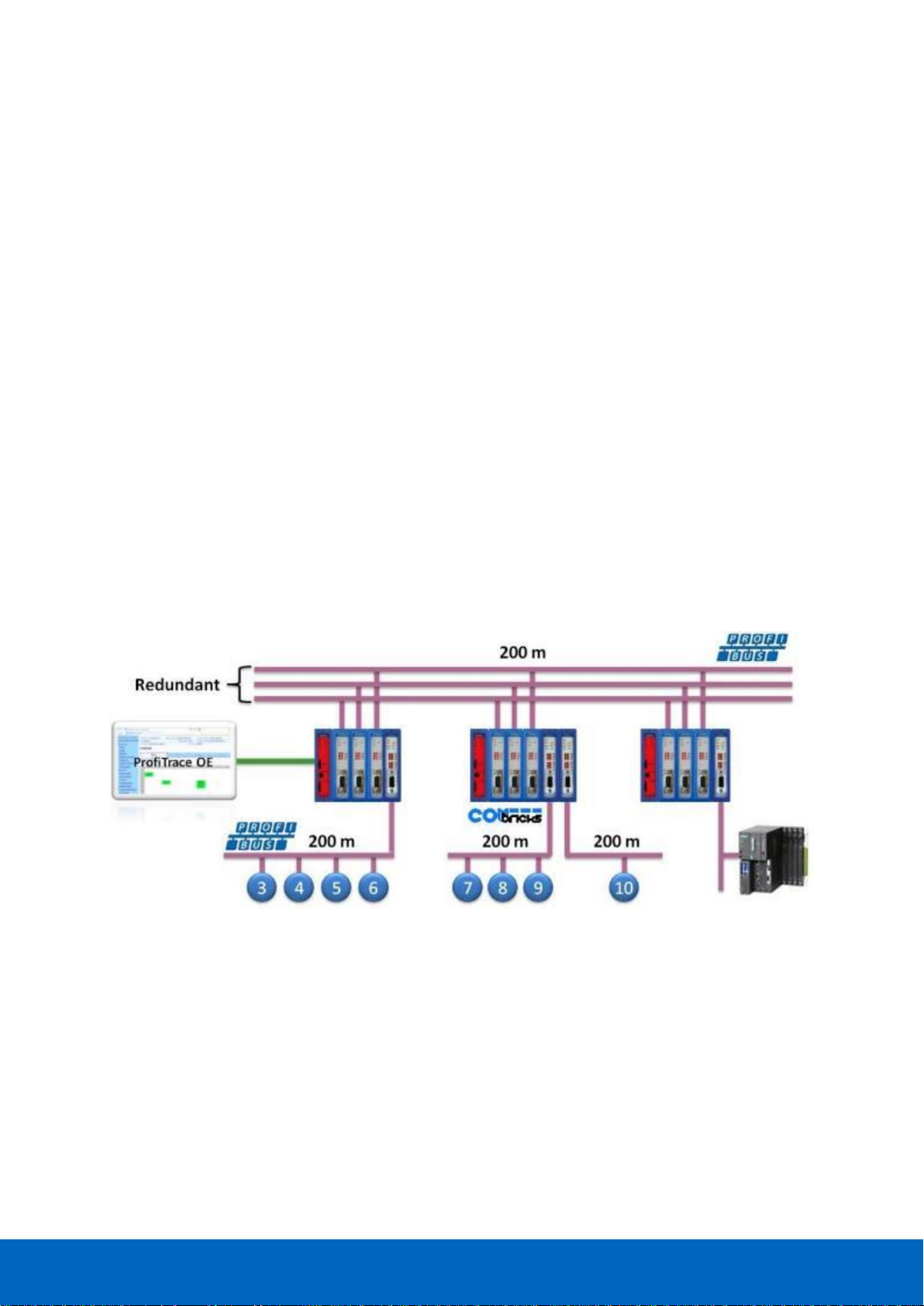
ComBricks User Manual v6.4.0 | January 18| © PROCENTEC 88/219
7.9 Redundancy
The bus redundancy technology of the repeater modules is very advanced. A redundant system can be built
using 10 parallel cables. This architecture provides extremely high availability. It is compatible with the RLM01
from ABB.
The redundancy procedure is very simple;
All the repeater channels of the specific application have to be assigned to the same network group. The
repeater channels that carry the redundant task have to be activated with the RED switch. After a reset or
power-up the redundancy system works directly.
ComBricks locks itself to the first redundant channel that has a valid start delimiter.
If this channel does not have valid telegrams anymore, ComBricks locks itself to the next redundant channel
with a valid start delimiter. There is no logic which redundant channel is selected.
It is recommended to use single-channel repeater modules for redundant applications. If a module
should fail, the replacement (pull/plug and wiring) will not affect the other redundant repeater
modules (channels).
Fig. 55 illustrates an application with 3 redundant segments. 3 Repeater modules of each ComBricks are set
with the RED switch set to ON and are wired to the redundant segments.
The devices and the controller(s) are connected to the regular repeater modules. The maximum amount of
devices which is allowed behind a regular repeater module depends on the application (between 1 and 31
devices).
Fig. 55 - Application with 3 redundant segments
Page 89
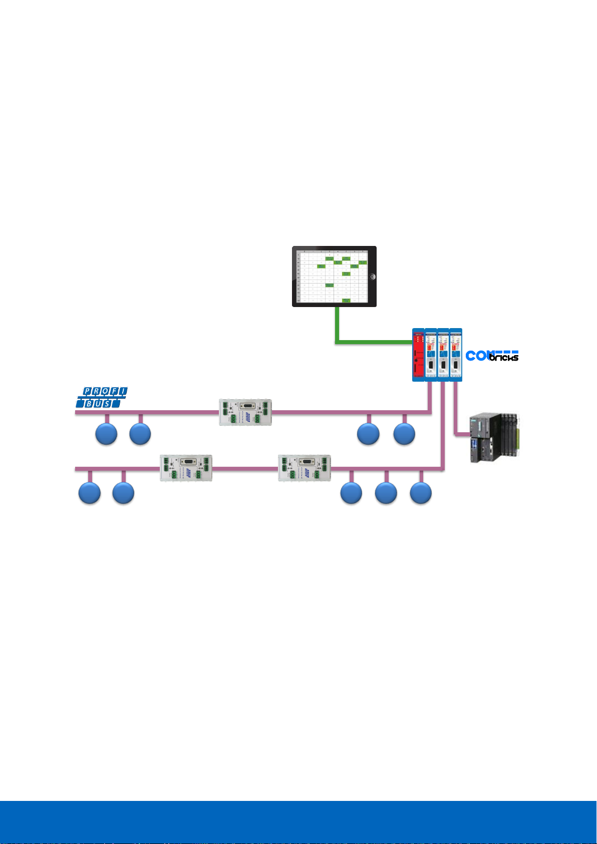
ComBricks User Manual v6.4.0 | January 18| © PROCENTEC 89/219
7.10 Mixing with other repeaters
Normally it is advised not to mix regular repeaters because of the limitation in cascading that these repeaters
have (caused by the bit width alteration due to internal opto-couplers and digital electronics).
ComBricks regenerates the telegrams (same as a ProfiHub or B1 Repeater). This means there is just a small
delay time, but no limitations in cascading.
If you mix ComBricks with other repeaters you only have to follow the cascading rules of the other repeater
manufacturer. If the other repeaters are also from PROCENTEC, you can cascade and mix without problems.
Keep in mind that monitoring will fully work, but the SCOPE repeaters only measure the signals up to the first
repeater module.
5 6 710 11
40 41
1.5 Mbps
3 4
200 m 200 m
Page 90

ComBricks User Manual v6.4.0 | January 18| © PROCENTEC 90/219
7.11 LEDs of the repeater module
The LEDs on the repeater modules are very useful for visual diagnostics.
Table 5 - LEDs on the standard repeater module
OFF
Blinking
ON
RDY
Repeater module has
NOT been configured yet.
Head Station is
configuring the repeater
module.
Repeater module has
been configured and is
operational
RX
NO valid telegrams
detected on this channel.
1 or more devices are
communicating on this
channel.
1 or more devices are
communicating on this
channel.
ER
The baudrate has
been detected.
Problem in the
cabling has been detected
on this channel.
This channel has not
detected the baudrate (yet)
or there is a problem with
the wiring of the cable.
SW
Internal termination for
this channel is OFF.
Internal termination for
this channel has been
activated.
Table 6 - Additional LEDs on the SCOPE repeater module
OFF
Blinking
ON
MIN
Valid telegram signal
amplitude (> 2.5 V)
Telegram signal
amplitude is too low
(< 2.5 V)
TERM
Valid idle voltage
(~ 1 V).
Idle voltage is too low
(< 1 V)
HWE
Repeater is
operational.
Internal repeater
error (contact PROCENTEC)
Page 91
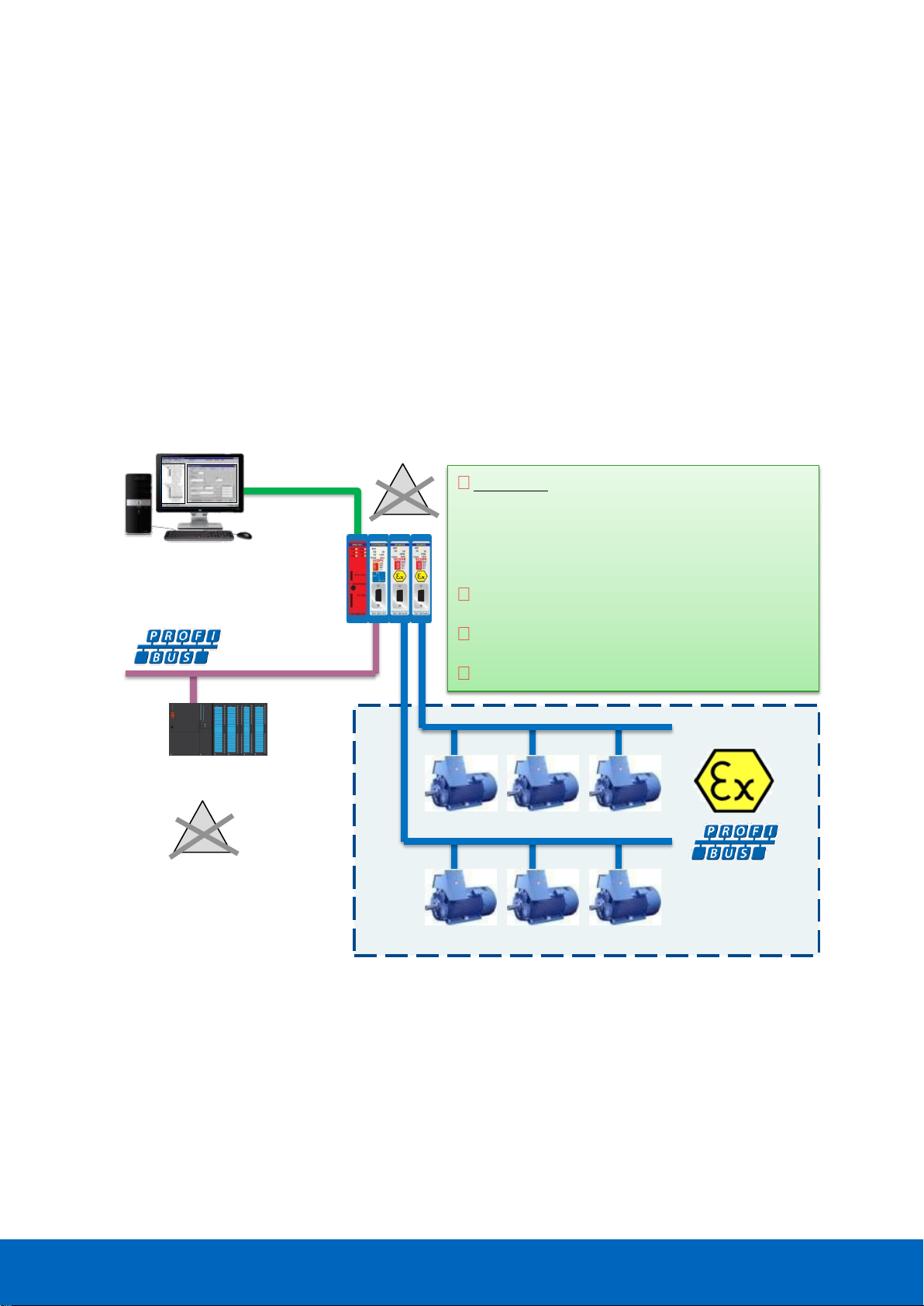
ComBricks User Manual v6.4.0 | January 18| © PROCENTEC 91/219
8 RS-485-IS Barrier module
The ComBricks RS-485 Intrinsic Safety barrier is capable of creating segments for use in potentially explosive
atmospheres. It complies with the specifications for PROFIBUS DP in IS segments and drives 31 RS-485-IS
PROFIBUS DP devices. ProfiTrace and an Oscilloscope are integrated and also suitable for Intrinsic Safety.
The RS-485-IS barrier is the only available product for remotely monitoring IS segments over Ethernet from the
safe zone. Because of the permanent mounting of the barrier, the user does not have to touch the installation
anymore. This avoids hot permits and other paper work.
As an alternative it can also be used as a busmonitor on existing IS segments created by 3rd party barriers.
The IS barrier can be mixed on the backplane with other ComBricks modules, such as the PROFIBUS PA, Fiber
Optic and regular RS-485 modules.
Ethernet
- ProfiTrace in a web server
- Oscilloscope in a web server
- FDT/DTM
PLC/DCS
The only Ex barrier with an integrated
ProfiTrace and oscilloscope for remote
monitoring over Ethernet from the safe
zone.
Can also be used on existing segments.
31 devices per IS module.
Certified for; II (2) G [Ex ia Gb] IIC
Zone 1 equipment
x
x
Page 92

ComBricks User Manual v6.4.0 | January 18| © PROCENTEC 92/219
8.1 Compliancy and certificates
The RS-485-IS Barrier module complies with:
II (2) G [Ex ia Gb] IIC
EN-IEC60079-0: 2009
EN-IEC60079-11: 2012
EN-IEC60079-25: 2010
PROFIBUS International IS Installation Guidelines
Certification number: DEKRA 12ATEX019
Fig. 56 - Dekra ATEX Certificate
Page 93

ComBricks User Manual v6.4.0 | January 18| © PROCENTEC 93/219
8.2 Channel structure
Every Channel is electrically isolated and internally connected to the transparent PROFIBUS networks on the
backplane (see Fig. 51).
The shielding of the PROFIBUS cable is grounded 1-on-1 to the DIN rail.
8.3 Connecting the cable
Connect the cable to the module with a DB9 connector on the front of the module. The DB9 connector must be
suitable for use in Intrinsically safe networks, and the internal termination shall have a value of 200 Ohms.
Do not connect a cable which is connected to non-IS components. This will damage the internal
electronics and makes the use of this module dangerous in Intrinsically Safe segments.
8.4 Grounding system
Always use Direct Grounding with the power supply and the shielding of the PROFIBUS cables. If you do not
want to ground all or some cables to the common ground, the cable shielding should be connected to pin ‘I’. A
capacitor with a parallel high value resistor will separate the 2 potentials (see Fig. 51).
If by accident the Direct Grounding is connected with the Indirect Grounding, the Direct Grounding “wins”.
8.5 Baudrate detection
Refer to paragraph 7.5 for a description of the baudrate detection.
RS 485-IS
Circuit
DB9
-IS
Isolation
Circuit
Isolated Area
DGND
To grounding of
other Channels and DIN-rail
4 PROFIBUS
Networks
(Backplane)
Network
Selector
NW0/NW1
1 2 3 4
To Ground Clamp on
bottom of module
Ex ia voltage
and current
limiters
Scope
Page 94

ComBricks User Manual v6.4.0 | January 18| © PROCENTEC 94/219
8.6 PROFIBUS DP cable lengths
The length of the PROFIBUS cable connected to the repeater channels should comply with the PROFIBUS DP
cable specifications for RS-485-IS.
8.7 PROFIBUS DP cable specifications
The cable should comply with the PROFIBUS DP cable specifications for RS-485-IS.
Table 7 - PROFIBUS DP cable specifications
Parameter
Value
Parameter
Value
Wires
2 (twisted)
Wire diameter
≥ 0.64 mm
Impedance
135..165 Ohms at 3..20 MHz
Wire area
≥ 0.34 mm2
Capacity
≤ 30 pF/m
Shielding resistance
≤ 9.5 Ohm/km
Loop resistance
≤ 110 Ohm/km
Baudrate (kbps)
Segment length (m)
9.6
1200 1200
19.2 1500500187.593.7545.45
200400100012001200
Example: 1000 m cable per channel at 187.5 kbps
PROFIBUS DP
Max. 31 devices
11 12 15
14
13
PROFIBUS DP-IS
Page 95

ComBricks User Manual v6.4.0 | January 18| © PROCENTEC 95/219
8.8 LEDs and DIP switches of the repeater module
The LEDs on the repeater modules are very useful for visual diagnostics.
8.9 Redundancy
Refer to paragraph 7.9 for a description of the redundancy system.
Dipswitches or web
server settings
Redundancy for the
current network
Communication
error or bad
telegrams
Data received
Repeater Module
status
Network 1: NW0 = L, NW1 = L
Network 2: NW0 = R, NW1 = L
Network 3: NW0 = L, NW1 = R
Network 4: NW0 = R, NW1 = R
Repeater internal
failure
The idle voltage
when no station is
sending is too low
Signal amplitude of
the telegrams
is too low
Page 96
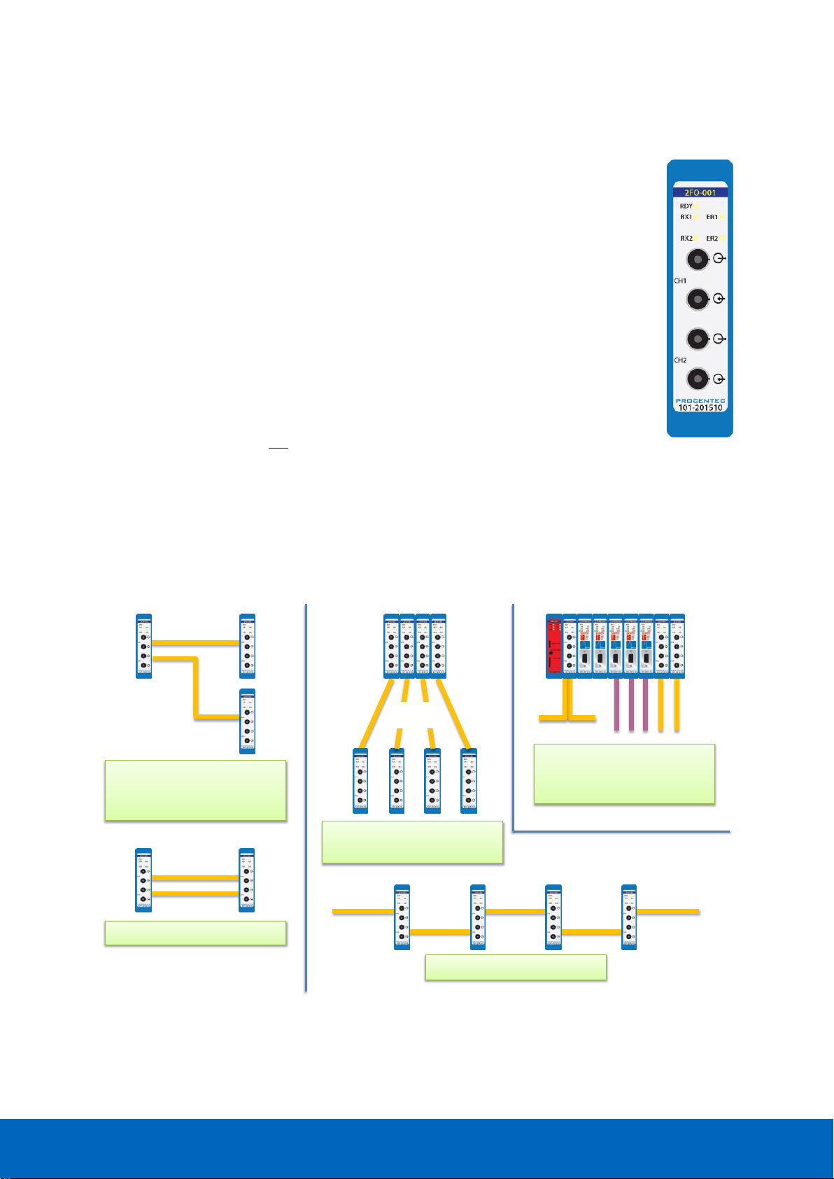
ComBricks User Manual v6.4.0 | January 18| © PROCENTEC 96/219
9 Fiber optic module (2FO-001)
The 2 channel PROFIBUS fiber optic module is suitable for 3 km multimode cable. This module
enables long cable distances and a galvanic isolation between devices and segments. It can be
deployed in a point-to-point, bus, star and hub topology.
The fiber optic modules can be placed side by side with repeaters modules. Just like any other
communication module, the channels are directly connected with the ProfiTrace OE core in the
Head Station. Busmonitor data is directly available in the web server.
ComBricks can easily be transformed to a fully dedicated fiber optic hub mixed with copper
segments. The hub topology delivers an optimized delay time and live expansion.
The advanced 12 Mbps core of the fiber optic module can be cascaded unlimitedly with other
fiber modules. It contains diagnostic LEDs and supports the redundancy feature. The fiber
connection is utilized by 4 ST/BFOC connectors.
The 2FO-001 does not support ring redundancy.
See chapter 10 for modules that do support ring topologies.
9.1 Topologies
The ComBricks fiber optic module supports multiple topologies: point-to-point, bus, star and hub topology (see
Fig. 57).
3 km
3 km 3 km
3 km
Point-to-point (redundant)
Point-to-point with split up
over the same or different
networks
3 km
3 km
Point-to-point in a hub
topology
Point-to-point bus structure
Mix of topologies and
interfaces in the same or
different networks
Fig. 57 - Fiber optic topologies
Page 97

ComBricks User Manual v6.4.0 | January 18| © PROCENTEC 97/219
Fiber optic communication is in all situations point-to-point where the receiver and transmitter wires are
crossed. The combination of modules can create complex topologies like; bus and star/hub topologies. Every
topology has its own advantages and disadvantages.
9.1.1 Bus topology with ComBricks
• Long delay time
• Long range possible (cascading)
• Extendable only at the ends (without adding new modules)
9.1.2 Star/Hub topology with ComBricks
• Relative short delay time (no busparameter adjustments required)
• Adjustable at any time
• More module are required
• High availability
9.2 Delay time
Fiber optic applications require a delay time calculation to adjust the Slottime busparameter in the
configuration of the master(s). ComBricks complies with the following formulas:
This is between 2 fiber optic modules! More calculations have to be done when more modules are involved
(see Fig. 58).
The total delay for the entire network has to be added to the Slottime setting in the busparameters of the
master.
FO cable delay =(5 ∗ 10
−6
)
× FO cable length × Baudrate
Example: 1.5 Mbps, 3 km FO cable
FO cable delay = 0.000005 × 3 × 1500000 = 22.5 TBit
Tdelay = (FO cable delay +(2 × Module delay time))× 2
Continued example: 1.5 Mbps, 22.5 TBit FO delay:
Tdelay = (22.5 +(2 × 1.8)) × 2 = 𝟓𝟐. 𝟐 TBit
Page 98
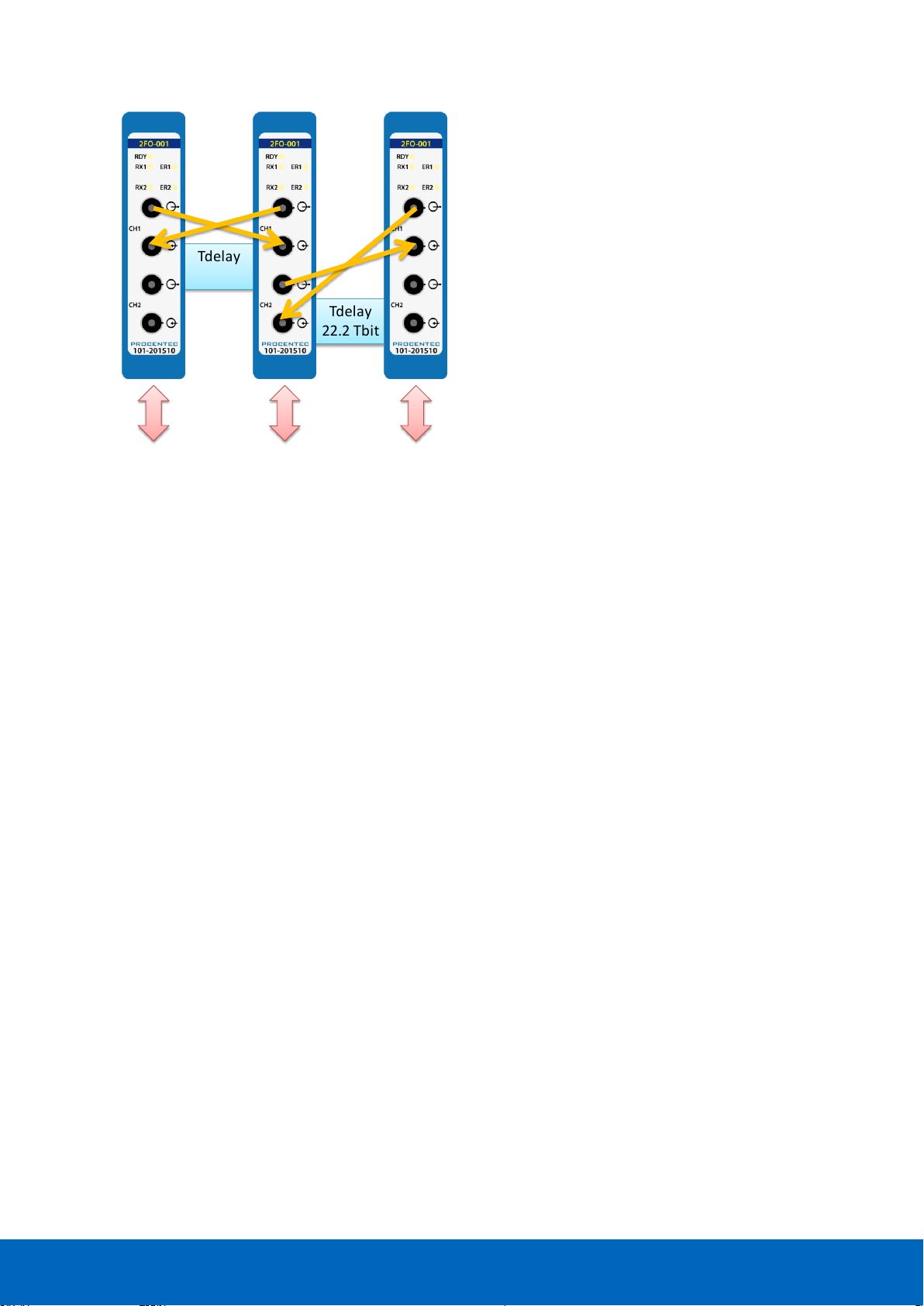
ComBricks User Manual v6.4.0 | January 18| © PROCENTEC 98/219
9.3 Baudrate detection
See paragraph 7.5 for an explanation.
9.4 Fiber optic modules in redundancy mode
For correct pass-through of telegrams in redundancy mode, keep in mind that the delay time is longer in this
mode. Increase the MinTSDR busparameter to at least 20 bittimes.
9.5 Use of FO modules in combination with other brands
When it is required that the ComBricks module connects to a third party optical link module, make sure to
enable the ‘Compatibility mode’ on the third party optical link. This will ensure normal operation.
Furthermore, short FO cables can cause an optical overdrive in the receiving side of third party optical links.
These links offer a ‘reduced power’ option to overcome this. The ComBricks does not suffer from the optical
overdrive problem, and has no reduced power functionality. In rare cases, when very short cable is used, this
can cause problems in the network. In these situations a 3dB attenuator should be used on the cable, or simply
use a longer cable.
Tdelay
22.2 Tbit
Tdelay
52.2 Tbit
backplanebackplane backplane
3 km
1 km
Fig. 58 - Fiber optic delay time
Page 99
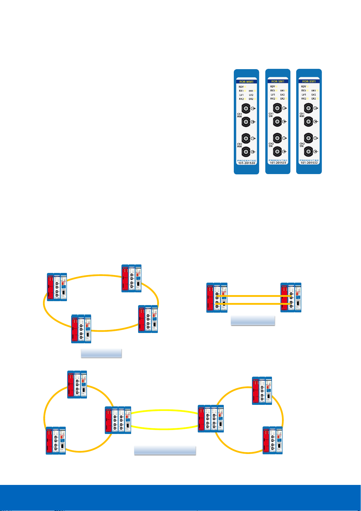
ComBricks User Manual v6.4.0 | January 18| © PROCENTEC 99/219
10 Fiber Optic Ring module (FOR-MM1 / SM1 / XM1)
The PROFIBUS Fiber Optic Ring module makes it possible to create
reliable ring structured fiber optic connections over multimode, single
mode or a mix of these modes. It is a galvanic isolation between devices
and segments and can be used over long distances. It is even possible to
create chain structured networks by using two or more modules in one
ComBricks set.
The fiber optic ring modules can be placed side by side with repeater
modules. Just like any other communication module, the channels are
directly connected with the ProfiTrace OE core in the Head Station.
Busmonitor data is directly available in the web server.
The use of mixed mode modules enables network designs with both
multimode and single mode paths. When using the XM1 module, make
sure to connect the multimode cable to channel 1 and the single mode
cable to channel 2.
Firmware version v1.288 or higher is required to run these modules. Please update your firmware
before using the Fiber Optic Ring modules.
10.1 Topologies
The ComBricks Fiber Optic Ring Module supports many topologies:
Multimode Ring
Single mode Ring
Mixed mode Ring
Redundant ring
Line, redundant
Multimode Ring
Multimode Ring
Single mode Ring
Redundant chain, mixed
Page 100
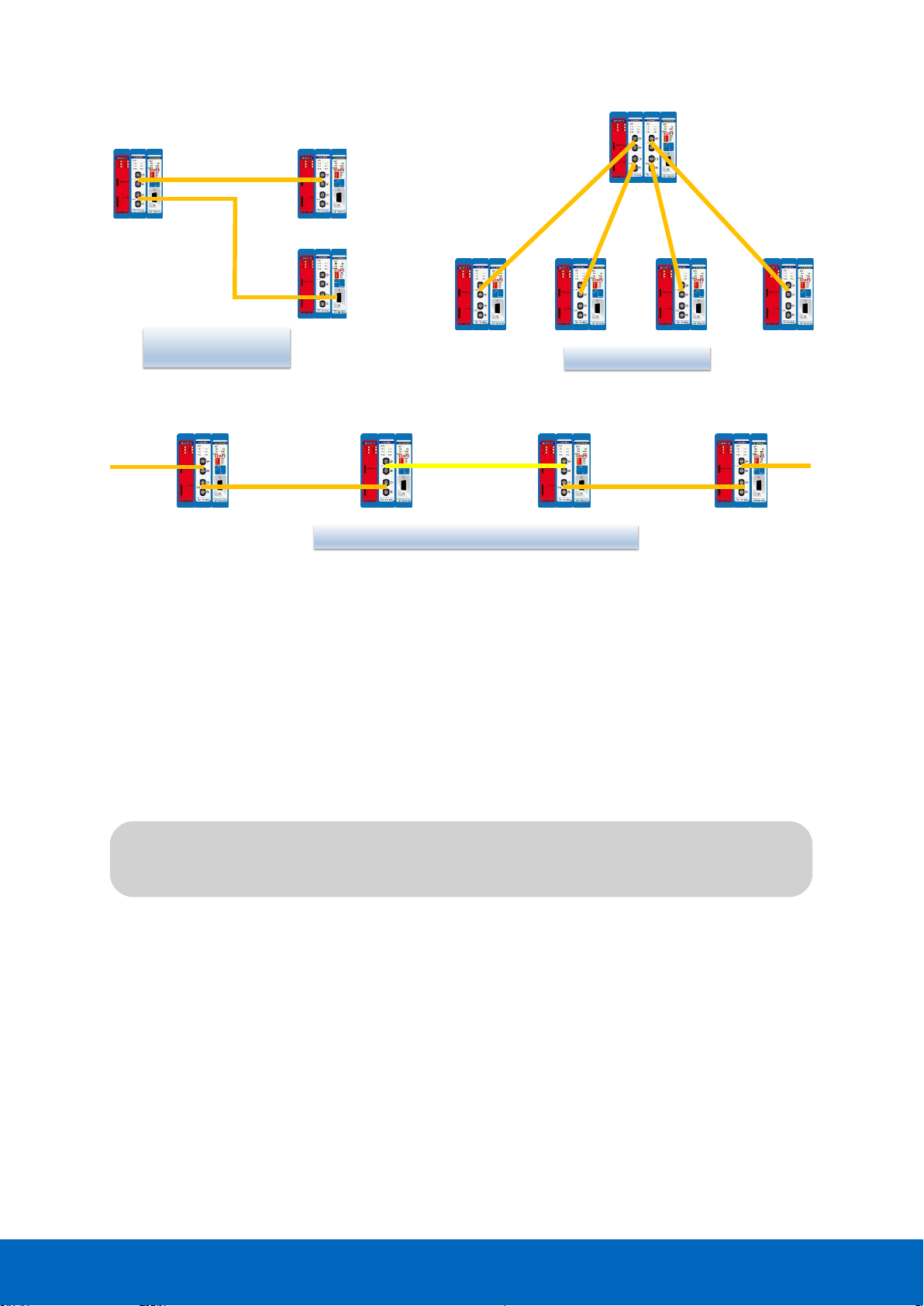
ComBricks User Manual v6.4.0 | January 18| © PROCENTEC 100/219
A ring topology must be connected from CH1 to CH1 and CH2 to CH2. Only with an uneven number
of FO modules, the cables may be connected from CH1 to CH2 and CH2 to CH1 (only once per ring).
10.2 Delay time
Fiber optic applications require a delay time calculation to adjust the Slottime busparameter in the
configuration of the master(s). To calculate the total delay including the fiber optic modules and extra time for
ring events, use the following formula:
FO
length
= Total length of fiber optic cable in km
FO
delay
= Delay of fiber optic cable per km in bit times (see table)
N
FO-modules
= Number of fiber optic modules in ring
N
delay
= Delay of one fiber optic module (see table)
The above formula can be completed with the values in the following table:
Line with split-up
over the same network
Line structure, mixed multimode and single mode
MM
SM
MM
T
SLOT
≥ Max
TSDR
+ (FO
length
× FO
delay
) + (N
FO-modules
× N
delay
)
Line in a hub topology
 Loading...