

Page 1

Owner's Manual
model number
CB400u
(Fits RT400/450/500 Routertops)
This upgraded cabinet base is designed for use with Model
RT400, 450, and 500 routertops. This cabinet uses Euro
hinges, and is predrilled for the optional two drawer unit shown
in the photo below (not included).
This carton contains all the necessary hardware to assemble
the cabinet. The hardware needed to attach the routertop
comes with the routertop. This includes cross dowels and
through bolts.
Please, take the time now to read these instructions, as it will
make assembly much easier.
Thank you for choosing Bench Dog, Inc.
Contents of Box
Hardware
32 1/4-20" x 50 mm round head bolts (2 extra)
32 1/4-20" cross dowels (2 extra)
2 nylon handles
4 #8 x 1" handle screws
2 Euro hinge sets- includes (4) hinges
and (4) plates
2 door stops with screws, #8 x 3/4"
Cabinet Panels
1 left side panel
1 back panel
1 right side panel with cord cut-out
1 upper shelf panel
1 lower shelf panel
1 left door
1 right door (with Bench Dog decal)
1 long support with (2) center through-holes
1 long support without through-holes
1 short support
Tools Required
4 mm Allen wrench
E
B
N
C
H
D
O
G
CB400u shown with optional
RT400 ProTop, AF400
ProFence, and DB400
drawer bank option
Bench Dog, Inc.
3310 5th St. NE
Suite 100
Minneapolis, MN 55418
phillips screwdriver
Symbols
Warning
!
I
Read and understand the entire contents
of this manual before attempting assembly
or use of this product. Inspect contents
for shipping damage and shortages. Report
problems directly to Bench Dog, Inc.
Important
QUESTIONS?
1-800-786-8902
T
O
O
L
S
612.782.8205 main
612.788.2518 fax
800.786.8902 toll free
benchdog@benchdog.com
www.benchdog.com
Be sure to check out our web site for all the
latest and greatest accessories and tools.
www.benchdog.com
2002 Bench Dog, Inc.
82-0005-01 1102
Page 2

General Conditions / Limited Two Year Warranty
We make every effort to assure that our products meet quality and durability standards, and warrant to the original retail
purchaser that this product is free from defects in materials and workmanship for two years. Remedy shall be limited to
Bench Dog's choice of repair, replacement or refund. This warranty does not provide remedy for consequential economic
loss.
This is a limited two year warranty. It requires the purchaser to contact Bench Dog in writing within 30 days of discovering
the defect. Warranty does not apply to defects due directly or indirectly to misuse, abuse, negligence or accidents, repairs
or alterations, or due to lack of maintenance. It excludes components and parts not manufactured by Bench Dog, defects
caused by failure to provide a suitable installation environment, and damage caused by use for purposes other than those
for which the product was designed.
Bench Dog, Inc. reserves the right to make product changes without notice and without obligation to make these changes
on products previously sold.
Important Safety Points
Before operating your router table and cabinet please read this manual thoroughly. Retain it for future reference. Refer
to your router owner's manual for safety instructions regarding use of that tool. This manual is not an instruction book
on how to do woodworking with a power tool. Bench Dog encourages all woodworkers to continually seek
improvement in their woodworking skills, regardless of their craftsmanship or years of experience. The router table,
fence, cabinet, and accessories must only be used for their intended purpose: woodworking via normal routing
operations. “Normal operations” means basic shaping of wood in conditions where grounded electricity, sharp tools,
dust, and rapidly spinning parts can be used or encountered safely. The following instructions elaborate on this
concept.
1. Do not use your router table or cabinet as a step or seat.
2. The top and cabinet must be properly secured, and be level before use. Inspect your table and base for
damage and levelness prior to each use.
3. Keep work area clean, dry and well lit.
4. The hardware affixing the insert to the routertop must be installed for safe use. Tighten insert hold-down
screws before each use.
5. Safe operation requires a router table fence, bit guard, dust collection system, starting pin or fulcrum, and
speed reducer for large diameter bits. We recommend reducing router speed for 1" or larger diameter bits.
Consult your bit manufacturer for the exact speed.
6. Use the right tool for the job. Do not force a tool or attachment to do a job for which it was not designed.
7. Secure your work with a featherboard, clamps, or a vice when appropriate. The use of inappropriate
accessories may cause injury.
8. Wear safety glasses, dust mask, face shield and ear protection. This is not an exhaustive list. Daily wear
eye glasses do not substitute for safety glasses.
9. Do not wear gloves or jewelry while using a power tool.
10. Maintain your equipment and its accessories in good working condition. Look for wear, poor alignment of
moving parts, binding of moving parts, breakage, poor mounting, or other conditions that may affect
operation and safety. Repair or replace any damaged parts.
11. Disconnect the power before moving, adjusting, or repairing parts, or otherwise maintaining your router table
and any accessories you may be using.
12. Keep children, pets, and those who may disregard safety away from work area, cords, sockets and tools.
13. Wear snug fitting clothes and keep long hair back to avoid catching in moving parts.
14. Do not overreach. Maintain balanced footing and stance.
15. Stay alert. Use common sense.
In any correspondence with Bench Dog, Inc., please refer to the date and place of purchase. You may reach us at
Bench Dog, Inc., 3310 5th St. NE, Suite 100, Mpls., MN 55413 USA, (612) 782-8205 or 1-800-786-8902. On the
internet, you may reach us at www.benchdog.com.
Page 2
Page 3

Cabinet Panel Detail
= Cross Dowel Hole
= Bolt Thru Hole
All cross dowels holes are
located on the inside of the cabinet!
cross dowel holes
for routertop mounting
LEFT SIDE BACK RIGHT SIDE
dust port
knockout
cross dowel holes
for routertop mounting
cross dowel holes
for routertop mounting
cord cut-out
Front Front
INSIDE
INSIDE INSIDE
To Back Panel
UPPER SHELF
This side up!
(cross dowel holes down)
door stop holes
To Back Panel
LOWER SHELF
This side up!
(cross dowel holes down)
LONG SUPPORT WITH THROUGH-HOLES
INSIDE VIEW
LONG SUPPORT WITHOUT THROUGH-HOLES
INSIDE VIEW
SHORT SUPPORT
RIGHT DOOR LEFT DOOR
INSIDE VIEW INSIDE VIEW
Page 3
Page 4
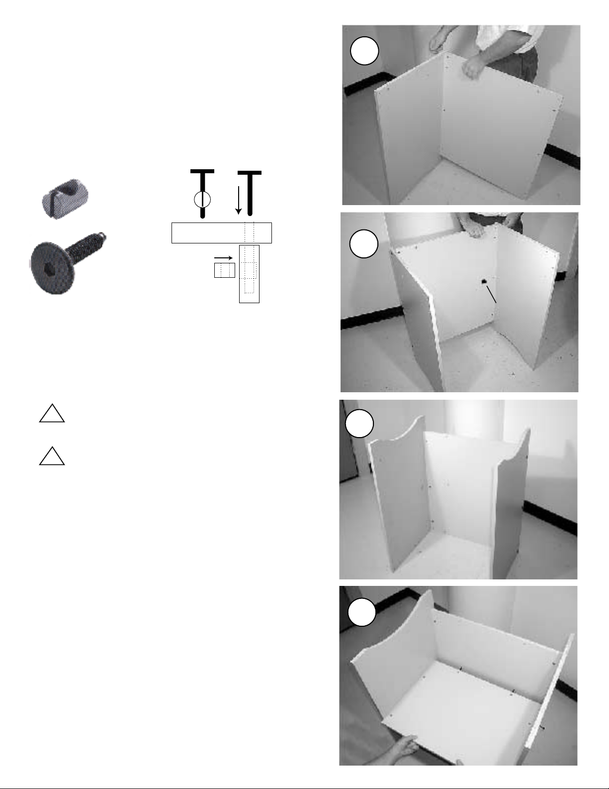
Assembly Instructions
1. Attach the left side panel to the back panel.
Use (4) 1/4-20 x 2" round head bolts and cross dowels,
and your 4mm wrench to lightly tighten the bolts. The
drawing below shows how these fasteners fit together.
Note: The cross dowel holes for mounting the routertop
are located on the top inside of the cabinet panels.
1
1/4-20"
cross dowel
1/4-20 x 2"
round head bolt
Note dowel
alignment!
Cross Dowel
Inside
of Cabinet
Bolt
Panel
Outside
of Cabinet
2. Attach the right side panel to the back panel.
Use (4) 1/4-20 x 2" round head bolts and cross dowels.
Note: the back panel has the power cord cut-out.
All panels forming the routertop mating
!
surface must be flush at the top.
Do not fully the tighten bolts until the
!
cabinet is completely assembled.
2
cord cutout
3
3. Turn the cabinet upside down.
This makes the following steps much easier.
4. Attach the upper shelf.
Preinstall the cross dowels into their holes. The cross
dowel holes face up, and the two small door stop holes
face down. (Hint: Install (2) round head bolts into the back
panel. As you slide the shelf into position, aim for these
bolts, as they will temporarily hold the panel in position as
you install the remaining bolts.) Note: The upper shelf is
positioned in the middle of the cabinet, not at the top of
the cabinet.
Page 4
4
Page 5

5. Attach the lower shelf.
See step four if you're unclear.
5
6. Right the cabinet.
You're almost done!
7. Attach the hinges and handles to the doors.
Press the hinge cups into their bores. Turn the integral
hinge cams to tighten, as shown in the photo. The (2)
nylon handles attach with the (4) #8 x 1" screws.
#8 x1" screw
for handle
6
7
8. Attach the (4) hinge mounting plates to the side
panels.
Note the orientation of the plates in the photo. The plate
resembles the letter "t". Position the top of the "t" nearest
the front edge of the side panel as shown.
Very Important! During installation shift all the hinge
plates down as far as they go. Tighten the plate
screws securely, but do not overtighten!
8
shift all plates
down as far as
they go!
Page 5
Page 6

9. Attach the (2) plastic door stops to the upper shelf.
Use the (2) small #8 x 3/4" pan head screws.
#8 x 3/4" pan
head screw
STOP!
9
Steps 10 - 12 apply to RT400 routertops only!
(skip to steps 13 - 15 for RT450 and RT500 routertops)
10. Attach the rear support.
Use the long support with the center through-holes and (4)
1/4-20 x 2" round head bolts and cross dowels.
11. Attach the front support .
Use (4) 1/4-20 x 2" round head bolts and cross dowels.
10
center
through-holes
11
12. Plug the unused holes, if desired.
To plug the holes you must first cut 1.75" off one end of
the unused short support. Then, simply bolt the cut-off to
the cabinet using (2) bolts and cross dowels.
GO TO STEP 16.
Page 6
12
Page 7

Steps 13 - 15 apply to RT450/500 routertops only!
(go back to steps 10 - 12 for RT400 routertops)
13. Attach the front support.
Use the long support with center through-holes and (4) 1/420 x 2" round head bolts and cross dowels.
13
center
through-holes
14. Attach the middle support.
Use the short support and (4) 1/4-20 x 2" round head bolts and
cross dowels.
15. Plug the unused holes, if desired.
To plug the holes you must first cut 1.75" off both ends of
the unused long support. Then, simply bolt the cut-offs to
the cabinet using (4) bolts and cross dowels.
14
15
16. Clip on the doors.
If your hinges need adjustment, see below. Please, take your
time to learn how the hinges clip on and off.
Frontal
Adjustment
Screw
Lateral
Adjustment
Screw
Don't force the hinges onto
!
the mounting plates!
Vertical
Adjustment
Screws
16
Page 7
Page 8

17. Tighten all bolts.
Tighten the bolts before attaching the routertop.
Additionally, the bolts will need periodic tightening after
using the table.
For mounting the routertop, use the instructions that
come with the top.
Important! Dust Collection
I
If you intend to keep the cabinet doors closed, you must install an aftermarket 6" dust port. A 6" dust port (universal flanges) are
widely available. We have provided a location and knockout for your convenience (see Step 18).
18. Remove knockout.
Remove the knockout from the back of the cabinet using a
hammer. Strike toward the inside of the cabinet to avoid
breakage of the laminate.
17
18
19. Remove excess material from hole.
Remove any excess material around the dust port hole.
20. Attach the dust port.
Position your 6" dust port over the hole and attach it using
4 screws.
Page 8
19
20
Page 9

Drawer Bank Option
Add a drawer bank to your CB400u cabinet with our
Drawer Bank Option. The drawer bank is constructed of
premium grade metal components, and the drawer fronts
match your cabinet. Model DB400.
Door Set
A set of two doors can be added to the cabinet. Includes
hinges, pull handles, door stops and screws. Model
DS400.
Cab-Loc Mobile Leveling System
Bench Dog has its own leg leveler and mobile base
combination! Call us or see your retailer for more
information. Model CL400.
Your own leg levelers can be added, however, make sure they are the bracket style that attach to the side of the cabinet
panels. DO NOT USE LEVELERS THAT REQUIRE DRILLING INTO THE BOTTOM OF THE END PANELS. An example of
this incorrect leveler is the stud and t-nut style leg leveler. This will weaken the panels. Dragging your cabinet on the floor
will cause serious damage to the integrity of the cabinet. Lift and place your cabinet where you need it. Such
damage will not be covered under the warranty.
Cab-Loc
DB400 Drawer
Bank Option
Door Set
Bit storage can be devised in many different ways, ranging from pull out bit shelves to holes drilled in wood and simply
placed within the cabinet. Our new drawer options are perfect for storing your router bits, wrenches, and collets.
H
D
E
N
C
O
G
B
T
O
O
L
S
Bench Dog, Inc.
3310 5th St. NE
Suite 100
Minneapolis, MN 55418
612.782.8205 main
612.788.2518 fax
800.786.8902 toll free
benchdog@benchdog.com
www.benchdog.com
QUESTIONS?
1-800-786-8902
Be sure to check out our web site for all the
latest and greatest accessories and tools.
www.benchdog.com
Page 9
 Loading...