

1
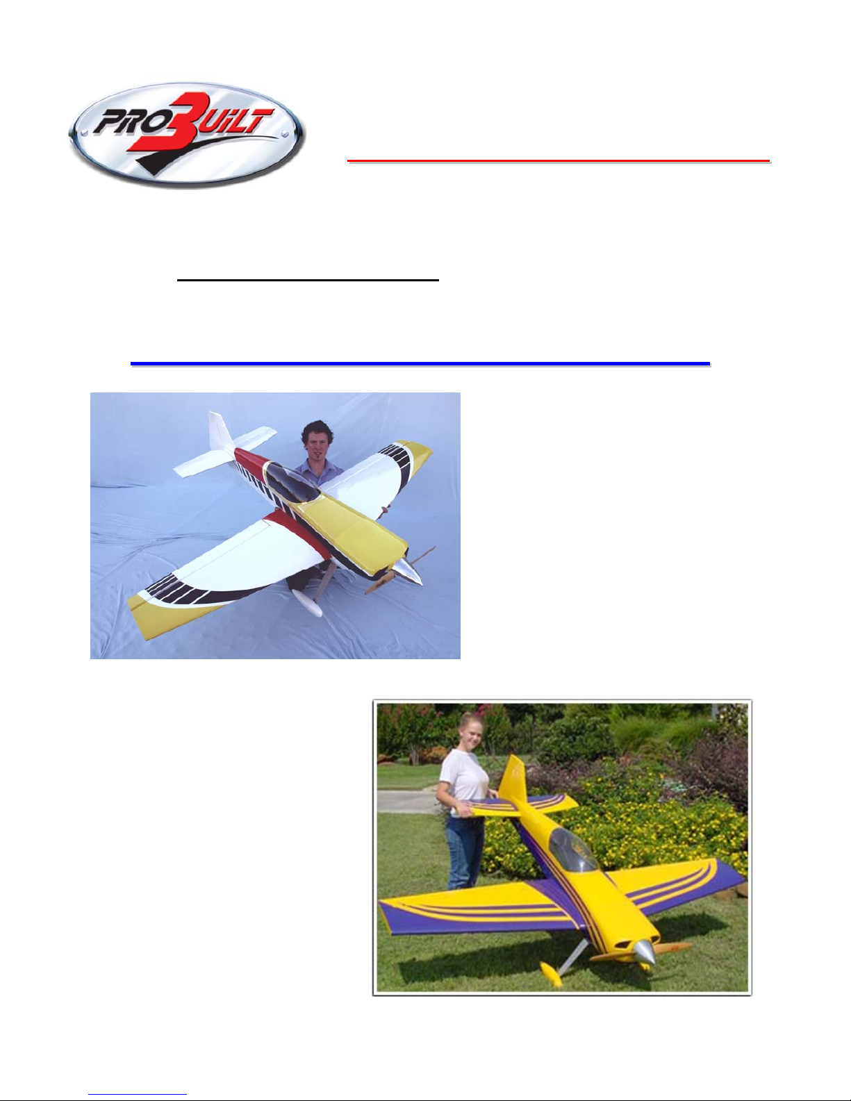
Pro Built ARF kit :-
G
GII
L
L
E
ESS 220022
-- 3355 %
% -- 9933”” (( 22..3366
m
m ))
A
Assssee
m
mbbllyy IInnssttrruuccttiioonnss

2
Specifications
Wingspan 93 inches ( 2.36 m )
Length 82 inches ( 2.08 m )
Wing Area 1560 sq. inches
Weight 22 – 23 Lbs ( 10.0 – 10.5 Kg )
Recommended Engine size -
60 to 80 cc gasoline – 35 to 60 cc glow engine .
( Not over 6 Lbs or 2.75 Kg weight )
Additional equipment required
Computer Radio with at Least 8 channels
2 Elevator servos minimum 100 oz/in. of torque each.
2 or 4 aileron servos, total torque required not less than 120 oz./in. per wing..
Rudder servo(s) at least 180 oz./in. (see text).
Throttle servo.
Radio operated engine kill switch or servo operated choke strongly suggested .
Single or dual radio battery packs at least 1650 mah total.
Switch[es] for receiver batteries.
Miscellaneous servo extensions..
High strength pushrods, carbon fiber reinforced suggested.
For Gas engine - Gasoline resistant fuel tank and lines with filler system.
3.5 inch wheels for main landing gear, 1.5 inch tail wheel.
3/16 inch axles for main landing gear.
5” spinner – Strongly suggest Tru-Turn alloy for required true - balance .
Heavy duty control horn set (3 or 4 sets required)
Please remember, this is a big airplane with high stresses on the controls. You must use
high performance servos, pushrods, linkages, horns, etc.
Flexing in linkage or loose hinges can and will cause flutter of the control surfaces which
will destroy the airplane in just a few seconds. Metal gear servos are required. Proper
installation of hinges is critical.

3
Table of Contents
1 Open and Inspect
2 Preparation and Improvements
3 Mount the Engine
4 Hinge the control surfaces
5 Mount the hatch and canopy
6 Mount the horizontal tail plane
7 Install control horns
8 Install servos
9 Install landing gear
10 Install fuel tank and fuel system **
11 Fit radio equipment **
12 Hook up throttle control linkage **
13 Fit wings
14 Check centre of gravity
15 Set control throws
16 Quick Start Guide
17 Warranty Information
** These Items require user supplied materials and creativity. These steps
assume that the user will be installing mounts, retainers, and other
assemblies to suit his particular building style. For example no servo mount
is supplied for the throttle, we have no way of knowing what type of engine
you will use or what is the best location for the throttle servo.
If you need advice on any of this, call us or email sales@tates.com.au
we’ll
be happy to try to try to answer your questions.

4
1. Open and Inspect contents
This section should be fairly self explanatory.
In the large box you should have a fuselage with hatch., wing tube and dual stab tubes, the
elevator/stab assemblies, the rudder, cowl, wheel pants, canopy, and a package with the landing gear, tail wheel bracket and miscellaneous nuts and bolts. Use some acetone on a rag to
clean the glue off the tubes. Under all of this is a false floor, and under that you will find the
wings with ailerons attached. The hinges are installed in the elevators and ailerons, but they
are not glued, you have to do that. The hinges for the rudder are in the hardware pack. We
have had good luck with two part Epoxy glues, as they fill any voids hinges and their sockets
.Wipe off any excess with Methalyted spirits before epoxy sets. The wings and ailerons are
made of sheeted foam, so be sure not to use any type of glue which might dissolve the foam.
Check everything for shipping damage and/or manufacturing defects. If there is a problem,
report it to us NOW, not after you start building the plane.
Read the quick start guide at the end of this manual first. It has
helpful hints and any errata corrections that may be available.
Before proceeding to any assembly, now is a good time to go over the whole plane and fix
any cosmetic flaws. Some cosmetic flaws are to be expected, this fact is reflected in the price.

5
2 Preparation and Improvements
There are a few areas where, at this unassembled stage, you can improve the final results of
your assembly project. There are many items that cannot be addressed on the assembly line
due to cost and possibly because not every improvement would be welcomed by every
builder. Here are a few items that have come up over time.
Go over the covering with a heat gun or iron. The covering tends to get loose over time
and with changes in temperature and humidity. It may have come out of the box with
wrinkles, I can assure you it did not go into the box that way.
Clean out the hinge holes. Without removing any wood, use a very sharp X-acto knife and
remove any covering that may have been pushed into the hinge holes. It is very important
that the glue sticks to the wood and not to the covering.
Hardening holes. The fuselage sides on this plane are made of balsa which in certain areas
is doubled by lite ply.
Using wood screws in balsa is difficult because balsa is very soft. It’s a good idea whenever
you drill a hole that must accept a wood screw to put a drop of thin CA into the hole and
then if necessary re-drill the hole. The CA will wick into the wood and harden it, adding
strength in that area.
Rudder servo tray. The rear rudder servo tray is not supported properly at the rear edge,
which causes rudder deflection to be less positive than it could be. This can be corrected by
adding a support across the bottom of the tray (1/8” x 3/4” balsa should do it) that attaches to
the fuselage sides.
3. Mount the Engine
The first thing to do, before anything else goes in the fuselage, is to get the engine mounted
and aligned with the cowl.. This is the hardest and most time consuming step in building this
plane. If you can do this everything else should be easy. Do this first before you hinge the
rudder.
Note that the firewall already has a proper amount of right thrust built in, do not use any
other offsets. When you shim the engine out from the firewall use shims of equal thickness
on all 4 corners so that you do not introduce any other thrust angles.
If you are using a twin, you have it easy. Set the engine on the firewall in approximately the
center. Mount the cowl using all 6 - 4mm screws.
To be sure that the cowl is in the right location. Move the engine around until the prop shaft
is centered in the cowl ring.
You can judge this better by putting the spinner back plate over the prop shaft. Once you are
satisfied with the location, remove the cowl (without moving the engine) and mark and drill
the firewall.

6
Install blind nuts from behind the firewall. Make a set of 3/4” square blocks that are thick
enough to place the engine’s prop drive hub 6.5” from the firewall and use these to set the
engine off from the firewall the proper distance. You can adjust the thickness to get an exact
fit.
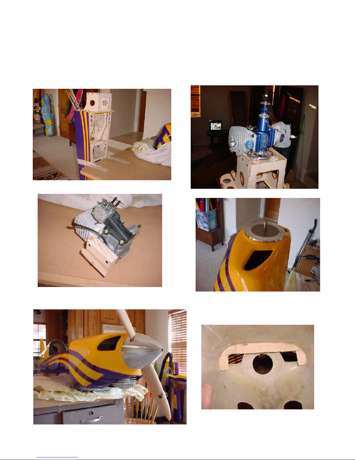
If you are using a single cylinder engine, you will need some method of keeping the engine
sitting on its mounting lugs without falling over. Here’s how to do this:
Make a wood spacer to go behind the engine that will place the engine’s thrust washer 6.5
inches in front of the firewall. Drill that spacer so that the spacer serves as a template for the
engine mount, and mount the engine to the spacer. In the photos is the mounting a 3W single,
which mounts from the rear, so simply countersink the mounting holes and mount the spacer
to the engine. This will work with other engines as well.
You will need to be able to hold the engine against the firewall and still move the engine
around to find the proper position. If the engine has a rear carb you will need to open up the
firewall for the carb to go through, but you will find it easier to remove the carb during this
fitting stage, then when the exact engine location is found you can cut the firewall to clear the
carb and then remount it. If you do that, be sure to seal the engine inlet so you don’t get
sawdust and debris in the engine.
Cut a strip of 1/4” ply about 3” long, and drill it in the center so that you can put a sheet
metal screw through it. The idea is to sandwich the firewall between the wood spacer and
the small piece of ply through the large hole in the firewall to allow the engine to move
around to position it. Put the screw through this wood piece, through the large hole in the
firewall, and into the engine spacer so that the wood spacer is snug against the firewall but
will still slide around.
Now mount the cowl using the supplied screws and washers. If you are using a single
cylinder engine it will be necessary to cut out the cowling to clear the cylinder to mount the
cowl. Cut a little bit at a time rechecking clearance until the cowl will fit over and mount on
the cowl mounting blocks with adequate clearance all around the cylinder.
Mount the cowl using all 6 supplied 4mm screws and washers. Place your spinner back
plate over the crankshaft or prop bolt so that it is centered. You can now just move the
engine around by hand (reach in from behind the engine) to get the spinner back plate
centered on the cowl ring.
Once the spinner back plate and engine are in the right position, remove the cowl and mark
the engine’s position by tracing the wood spacer on the firewall. Remove the spacer from the
engine and put it back on the firewall exactly where it was before, and use the wood spacer as
a template to drill the engine mount holes in the firewall. Secure the engine temporarily to the
firewall, and recheck the crank position in relation to the cowl.
You may want to f i n e a d ju s t t he engine spacer so that the spinner back plate fits perfectly. If
you do this remember that the firewall is already set with proper thrust angles, so make all
spacers the same thickness or it will change the thrust angle and the way the plane flies.
It is important for engine cooling that there be ample area opened up to allow hot air to be exhausted from the cowling. Normally this is done by opening up an area on the bottom of the
cowl, at the rear/center. A rule of thumb is the exhaust area needs to be at least twice the size
of the air inlet area.
7
If you are using a twin cylinder engine, it may be desirable to install a baffle inside the cowl
to force air to flow over the engine instead of around it. This can be as simple as a piece of
cardboard in the top of the cowl behind the engine. See the photo. This is something that will
be based on what engine you use.
8
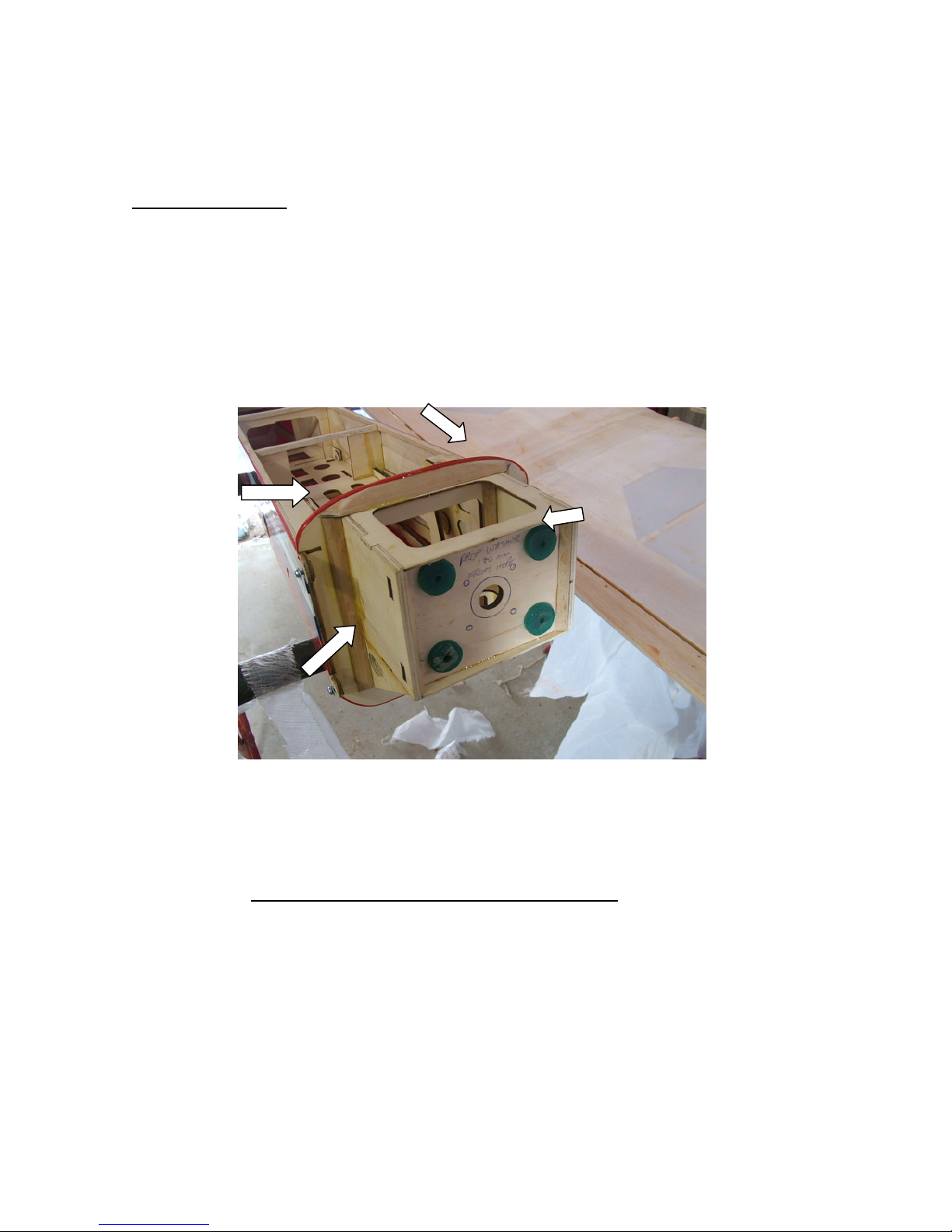
Engine Firewall . Especially if you are using a Gas engine or not using a soft mount system,
we strongly suggest adding some gussets to the firewall area. Always use Epoxy for engine mount
structures due it’s superior strength. Add the 1/2'” triangle balsa stock or similar together with an
extra plywood gusset as shown in the photo below. This will prevent any de-bonding of the
firewall areas.
4. Hinge the control surfaces
Hinging is a very simple matter. We recommend that you hinge all the control surfaces in
two steps allowing the glue to dry between steps.
There’s an important note about hinging the ailerons at the end of this section.
Before you start gluing anything, test fit each control surface. Aileron to wing, elevator to
stabilizer, rudder to fin/ fuse, with the hinges in place. Make sure the hinges go in the holes
smoothly and that there is ample room for the hinge “knuckle” so there is no large gap

9
between surfaces. The hinge lines are beveled. The point of the bevel should be at the center
of the hinge pin, this assures that the hinges are aligned and centered on the hinge line.
Once you are certain that they all go together smoothly, take one surface and remove the
hinges. Glue the hinges into the holes securely using the glue you prefer. Many people prefer
epoxy for this, We have had good luck with two part Epoxy glues, as they fill any voids in
the hinge sockets .Wipe off any excess with Methalyted spirits before epoxy sets.
Glue the hinges into one surface at a time , and you can do one half of the set at a time only.
Eg glue the hinges on one aileron only - let this set the glue this assembly to the wing,
wiping off any excess as you go.
Make sure that the hinge axis is correct for the surface being glued as well this will avoid
any binding of the hinge.
Check hinge operation every few minutes as the glue sets wipe off any excess that oozes from
the glu e joint.
It’s also a good idea to put some lite oil (like WD40) on a rag, and to wipe the edges of the
hinging surfaces with this rag. The oily residue will keep spilled glue from sticking to the
covering.
Whatever you use, put a drop of light oil (like 3-in-1) on the hinge knuckle after gluing. Be
careful that no oil gets on the shaft of the hinge prior to gluing.
When the glue is dry, do the same thing with the mating surface, glue the hinge legs into the
holes provided. Work the surface back and forth to be sure it moves smoothly. Do this every
few minutes as the glue sets to be sure you haven’t glued the hinge solid, but be careful not
to pull the hinges loose. Keep the surfaces as close together as possible to minimize gaps.
When completed it’s a good idea to seal the hinge gaps by ironing a piece of Ultracoat covering material into the groove between the surfaces.
Repeat this on both elevators and both ailerons. For the rudder you may wish to wait until
later to do the final installation of the rudder, it makes it easier to handle the airplane.
Important note about hinging the ailerons.
The beveled balsa strips at the back of the wing are glued to the inner foam core. The
foam is not very strong, so be sure that the hinge is glued to the balsa all the way up to
the surface. Glue the hinges into the wing first, then glue the ailerons on later. Be very
careful that the glue goes all the way down and all the way up to the top of the hole and
that it is contacting t he hi nge and th e w o od all the way around. If you just glue the hinge
to the inner foam eventually it will come loose. Trim away any covering that is
protruding into the hole, but don’t remove any wood if you can help it. Don’t drill the
holes bigger either.

10
5. Mount the hatch and canopy
The hatch mounts to the fuselage by two tabs on each side that are attached at the rear of the
hatch.
Set the hatch on th e f us e a nd m a rk t he f u se la g e so you can see where the fore and aft edges of
the mounting tabs are. Find the center between these two marks and measure down 1/2 inch
from the fuse t op edge a nd make a mark. With the hatch in place drill a 1/8” hole at the mark
you made through the fuse side and the hatch tab. Don’t push real hard when drilling the
hatch tab, it can be broken by excessive force.
Once the hole is drilled you may want to harden the wood around the hole in the fuse side by
putting some thin CA into the hole.
Install a 4-40 blind nut in the backside of the tab. Use a 1” long 4-40 screw ( Use allan head
bolts because if a screwdriver slips it will usually poke a hole in the cov ering) through the
fuse into the retaining tabs to secure the hatch to the fuse.
Trim the canopy to fit the hatch. Leave a small lip in the front, it makes the attachment more
secure.
Attach the canopy with whatever is your favorite method. Some people use tape, some glue
the canopy down, some use small screws. This is up to you. If you use small screws add
some hard wood such as 1/16” ply to back up the balsa wood of the hatch.
You might want to add a second set of hatch hold downs in front of the canopy. This is a
change that will be added on later models of the G202. It adds a degree of redundancy and
also quiets the airframe noise somewhat.

11
6. Mount the horizontal tail plane
Trim the covering around the holes in the fuse for the stab spar tube and the two retaining
bolt holes on each side. You should also cut away the covering over the holes for the elevator servos, but don’t cut out the rudder servo covering yet.
Slide the spar through the fuse, and slide the stabilizers onto the tubes from each side.
Retain the stab to the fuse with two 4mm bolts, washers and lock washers. I advise you to use
washers and lock washers or a little blue loctite on the threads. Don’t use a lot, and don’t use
red loctite, or you won’t be able to get the screws out without tearing out the blind nut.
The assembled stab with controls is shown here: ( photo of Extra - but is similar to Giles )

12
7. Install control horns
Good quality heavy duty control horns must be used on these aircraft.
You should decide whether you care if the screw head shows on the upper surface. The hard
points are already pilot drilled, but need to be made larger for the 8-32 stud. I have found that
grinding a small flat on one side of the tip of the 8-32 stud makes it thread into the hard point
more easily.
IMPORTANT NOTE:
Do not drill the hard points larger than 9/64. The screws must thread snugly into the
hard points. If you drill it larger the screw can wobble in the hole and allow the control
surface to flutter with disastrous results.
If you don’t care about the screw head showing, drill all the way through the hard point in
the aileron and elevator with a 9/64 drill. Also drill the upper hard point in the rudder with
the 9/64 drill, save the lower one for later. Countersink the drilled holes in elevators and ailerons on the top.
On ailerons and elevators install the 8-32 stud from the top, screw it all the way in until it is
snug. Install the rest of the horn assembly from the bottom.
Or;
Another way to do it does not allow anything to show on top. Very carefully and slowly
drill from the bottom side with a 9/64 drill, following the pilot hole so you don’t change the
angle. I use a hex drive quick change bit and put it in my power screwdriver which turns
slowly and is easy to handle. Pull the bit out every 1/8” or so and blow out the shavings.
While drilling observe the top surface of the hard point visually. When the drill reaches the
covering on top you should be able to see it bulge before the covering is pierced. As soon as
you see it, stop drilling and withdraw the drill, blow out all the shavings.
Now take your 8-32 stud and thread it into the hole from the bottom. Screw it in by hand or
with a power screwdriver, again observing the other end, until you can see the tip of the
screw through the covering.
Now, cut off the head of the stud/screw and thread the rest of the hardware onto the screw.
Here’s a tip. When you cut the head of with your Dremel, it will be hot. Don’t let it fall on
your legs or on the surface or it will burn through the covering (or your skin or pants).

13
Rudder tiller;
After the upper hard point has been drilled through with a 9/64 drill, install the tiller bar so
that it is showing the same amount of threads on each side of the rudder. Once the stud is
installed cut the head off with your Dremel.
After the tiller bar is installed, if you need to adjust the position you can do this without
damaging it by double-nutting two 8-32 nuts and use a wrench to turn the stud into the
hard point.
Now install the horns exactly the same distance from the rudder surface. If using the DuBro
horn set for this you should re-drill the horn with a 1/8” bit in a location that is even with the
hinge center line/ Both horns should be drilled at the same point. Then trim the excess from
the horn, leaving at least 1/8” of material at the end.

14
8. Install servos
1. Elevator servos.
Trim away the covering from the rear sides of the fuselage to expose the two servo trays.
Attach a servo extension to the servo cord long enough to reach the receiver, and tie this
servo connector together with dental floss or whatever you prefer.
Slide the extension through the servo hole and fish the end through the fuse with a piece of
wire with a hook or whatever you want to use. Servos should be secured with all screws.
There are two fuselage formers that have lightening holes in them. If you run the extensions
through these holes it keeps the wires from flopping around in flight.
2. Aileron servos.
There is a servo wire tunnel through the wing that touches the servo tray. You can use a
piece of wire with a hook to fish through the hole and pull the servo pigtail through. Be sure
the extension is long enough to reach the receiver.
You need to decide on 1 or 2 servos per wing. 1 servo is lighter and cheaper, however if the
linkage fails the aileron will flutter and you will lose the airplane.
I strongly suggest dual aileron servos. If you use two, use the inner and outer servo tray. Use
the center tray for a single servo.
I recommend that you cover over the unused tray(s) with Ultracoat.
3. Rudder servo.
Do this last, after everything else is done and the plane is otherwise ready to fly.
Balance the plane and determine if weight is needed in the tail.
If tail weight is required, mount two servos in the tail below the elevator servos in the same
manner as the elevator servos.
If tail weight is not needed, mount a single powerful digital servo such as a JR 8611 or Hitec
5945 in the servo tray and use pull-pull cables to actuate the rudder. If necessary there is a
second servo cutout which can be used to gang two servos for the rudder
and still use pull – pull.
You can use a high powered standard size digital servo such as JR 8411 or Hitec 5945, or if
you feel more power is needed use a 1/4 scale type servo such as the Hitec 5735 digital. This
requires that you remove a small amount of lite ply from the tray, and glue down two rails
about 3 inches long to mount the servo. If you do this, the rails may need to be shimmed up
to keep the servo bottom off the bottom of the model.

15
Below the rudder servo trays in the tail there are two small slots. These are for the pull-pull
cables. Please note that in building 2 prototypes and 2 production models, in every case the
plane has balanced acceptably (more or less) without the rudder servos in the tail. Using a
pull-pull is desirable unless you are using a heavier engine.
All the test planes used either a BME 102, a ZDZ-80 single, or a 3W 75F single. These engines all weigh roughly the same, under 5 pounds ( 2.3 Kg ) bare.
4. Throttle and (optional) choke servo installation.
We recommend that a small servo be used to operate the choke as well as the throttle. This
provides an extra level of safety by acting as a secondary engine kill mechanism in case of
failure in the throttle control system.
It is impossible to anticipate every potential throttle layout for every engine, so make sure
that the installation is according to the engine’s manufacturer.
9. Install landing gear

16
There should be drilled holes in the landing gear plate under the covering, these should match
up with the holes in the landing gear. Unfortunately the holes are not always there. To assure
perfect alignment use the following procedure. If the holes are not there center the gear so the
holes align with the aluminum bracket inside. The front edge of the gear should be back
about 1/2 to 3/4 inch from the front fuselage former edge. Drill one of these holes through the
aluminum bracket and mount the landing gear with 4mm screws and locknuts. Then use the
landing gear as a template and drill the remaining holes as well and use 4mm screws and
locknuts there also.
Keep the front edge of the gear parallel with the front former.
To mount the wheel pants you simply drill through the back of the landing gear and through
the wood backing plate. Install a 4-40 blind nut in that wood backing plate.
The tail wheel bracket attaches to the hardwood plate at the bottom of the tail using two wood
screws.
Use springs from the tail wheel tiller for controlling the tail wheel.
See the accompanying photo.

17
Steps 10, 11 & 12 Install fuel tank and fuel system – Mount the
radio control equipment and throttle control.
These 3 subjects ar e c omb in ed be caus e th is i s t h e part wher e yo u g e t t o d o things your
way. We have only done a few things to get you started.
There are holes cut in both fuse sides that will fit any of the popular integrated switch/
charge jack assemblies. These are available from Maxx Products, Hi Tech, JR,
anprobably several other vendors. Some trimming may be required
1. The fuel tank can be mounted on the tray beneath the wing tube. Putting it there mini-
mizes changes in balance as the engine burns off fuel.
2. There is a tray at the rear of the radio compartment which will hold two battery packs and
one standard rudder servo. It will hold a large rudder servo with a slight modification if you
feel the need to have a great deal of rudder power.
3. There is a small tray in the center of the radio compartment which is meant to hold a re-
ceiver.
4. There are slots cut in the various trays. We used a double sided velcro strap to hold com-
ponents in place. It is available at hardware stores. Also use tie wraps in certain places to
make things more secure.
If you use a 5 pound ( 2.3 Kg ) engine, and lay the components out the way we are showing,
the plane will be very close to its proper balance point without any ballast.
Please use good strong pushrods and other linkage parts.
A sample of the assembly to use is shown below.
Notice the carbon fiber pushrod assembly, made from hollow carbon tube and a 4-40
threaded rod through the centre, kept short and fixed at either end by nuts.
The servo connection is Sullivan 4-40 or Dubro clevises – Do not use ball-links, as they
cause a twisting force on the servo arms that will fatigue and fail.

18
aking pushrods that will withstand the forces involved in a large plane of this type is very
simple once you see how it is done. If you have your own design, feel free to use it, but
here’s one that is cheap and strong.
You will need a length of 3/16” carbon fiber or fiberglass tubing, a length of 4-40 allthread rod, and some 4-40 nuts.
First, set up your linkage using the clevises and the 4-40 all thread cut to the proper length.
You can make all your pushrods at once, so get all those rods set to the right length. If you
use a metal clevis, be sure the pushrod goes all the way into the threaded section, plus a little
to allow a range of adjustment. With plastic clevises like Dubro , the rod should screw into
the clevis about 1/2 inch to be sure there is sufficient strength.
Measure each pushrod, and cut a piece of carbon-fiber tube that is 1 1/2” shorter than the
rod. Slip the tube over the rod and tighten down a nut from each end so that you leave an
equal amount of thread at each end to mount the clevis. Tighten the nuts slightly so they
don’t come loose and so there is a little tension on the rod inside the tube.
13. Fit wings
Push the 1.5 inch aluminum tube spar through the tube in the fuselage until it protrudes an
equal distance on both sides.
Carefully push each wing onto the tube until the anti-rotation dowels engage the holes in the
fuselage side. As the wing approaches the fuselage guide the aileron extension through the
access hole.
The wings mount to the fuselage with two 4mm socket head screw on each wing through
the fuselage side. You can also drill the ant rotation dowels to accept hairpins for safety
(see photo).
Use no larger than a 1/16” drill and pin to avoid weakening the dowel. Do not rely on the
dowels alone, they are not meant to be used as permanent retainers but will work in an
emergency.
Use a large washer on the 4mm screw to keep it from pulling through the hole in the fuse
side, or install a small aircraft ply “cookie” as shown to reinforce this area.
The holes are intentionally made slightly oversize to allow for alignment variances, but
once your cookie is properly positioned you can glue it in place with thin CA to make a
permanent and accurate installation.

19
14 & 15. Check centre of gravity & Set control throws.
Balance the plane.
First flights should balance 1” in front of the center of the wing tube.
Note this is a change from the earlier 1 3/4” to 2” which was a very conservative setting.
We balanced the plane on a dowel after first marking the balance point on the bottom of the
fuselage.
If your plane is tail heavy, consider moving batteries as far forward as possible, remove
anything from the tail that might be adding weight, get a lighter tail wheel, heavier ignition
battery. Remember that the farther weight is from the CG the less of it you will need. A
small weight on a long arm makes a big difference. A heavy spinner has more effect that a
bigger battery because it is farther from the CG.
Your flying style may require a different balance point, but this is a good safe starting point.
When making CG changes always do it a little at a time or you could find yourself flying a
plane that cannot be landed.
Control Throws
We set the control throws as follows on planes in test. Please keep in mind the high rates
specified here are for 3D, not for just faster response.
The elevator in particular at these rates will cause instant stalling, tumbling, and all sorts of
other things that can only be done at low speeds.

20
Do not use the 3D settings until you are thoroughly familiar with the plane on low rates.
High rate (3D) Low Standard/ initial rates
Ailerons 20 deg 16 deg
Elevators 40 deg. 13 deg.
Rudder 45 deg. 25 deg.
Fly the plane on low rates at first.
At high 3D rates,it can be very difficult to fly these models
Use switchable hi / lo rates and / or exponential settings in your
transmitter to make control LESS sensitive around centre of control , for
smoother flight.
The 3D rates are intended only for extreme aerobatics.
16. Quick start guide and hints.
This page is the place to start if you are an experienced builder. It will save you a lot of time.
If you are not an experienced builder, read it anyway, you may not need to go any further.
Hints and notes.
Almost everyone likes to make improvements so here are some hints to improve the plane
and the experience. You will n o tice tha t I am very big on redundant systems. Multiple of
everything is the safest way to go.
Use washers and lock washers on the h-stab retaining screws. You can use a little blue
loctite, but too much or using red loctite will probably cause the blind nuts to rip out when
you try to remove the screws.

21
Before installing rudder controls wait until the airplane is completed and check the balance.
You can use pull-pull if little or no tail weight is needed, otherwise there are two servo
mounts in the tail for rudder servos if the plane is nose heavy.
You might want to re-glue the hatch hold downs to the hatch, they have been known to
come loose. The hatch can benefit from a second set of hold downs also.
I strongly recommend dual aileron servos for safety. In testing, one aileron linkage failed
when the arm fell off the servo and the ensuing flutter caused pushrod on the opposite aileron
to fail. However dual servos are not required, the plane flies beautifully with a single Hitec
5645 digital servo in each wing.
Use a backup engine kill device besides the throttle. I use a servo to actuate the choke which
can also be used to kill the engine, but a kill switch is a good solution also.
Balance the plane carefully. The Giles wing does not like to be tail heavy.If you fly it tail
heavy it can be beyond the capabilities of the best pilot. Balance initially at 1” in front of
the centre of the wing tube and work back a little at a time. In testing we have found that
with a 5 pound engine the plane will come very close to balancing with pull-pull. With a
lighter engine the plane, even with pull-pull, will likely be tail heavy. In that case consider
using a heavier spinner and/or ignition batteries. The plane can be made to balance without
ballast if you do some planning as you install things.
1. Open and inspect everything. There should be a fuselage with hatch, wing tube and stab
tubes. Also 2 stabs w/elevators, rudder, landing gear and hardware (nuts and bolts)
package, cowl, canopy, wheel pants. Hinges are either in the control surfaces or supplied
separately, but they are not glued in yet.
2. Mount the engine. Distance from firewall to cowl face is 6.5” (more or less The cowl
mounts are already set, use the cowl ring to align the engine. Right thrust is already built
into the firewall.
3. Glue the hinges with whatever you like to use, but epoxy is probably best
4. Hatch mounts are obvious, drill 1/8” hole and use a 4-40 blind nut inside. Mount the
canopy us ing t h e m e th od y ou p r ef e r ; s c r e ws , t ap e , g lu e . W h a te v e r works for you.
5. The horizontal stab assembly mounts on one 1/2” aluminum tube. Two 4mm screws
are used at each side to retain the stab assemblies Use loctite on these screws, and use
washers and lock washers on them as well. Blue loctite is appropriate.
6. The control surfaces have pre-drilled hard points to accept rocket city type horns. There
are three hard points on the ailerons. Use the center hard point if using a single servo, the
inner and outer hard points are for dual aileron servos. The rudder has two hard points,
the upper one is for the tiller and the lower one is used to steer the tail wheel. Do not drill
the lower one out, a 6-32 tiller is sufficient in that position.
7. Servo installation should be obvious. Elevator servos trays are located in the tail below

22
the horizontal stab. Rudder servo trays are below the elevator servos. Don’t cut o u t t h e
wrong one, and don’t cut ou t the r ud der s ervo trays until you are sure you will be using
tail-mounted servos. Slots for pull-pull cables are located below the rudder servo trays.
Whichever aileron configuration you choose, cover the remaining unused servo tray(s)
with Ultra coat. Throttle servo installation is up to you.
8. There are two drilled holes in the landing gear plate under the covering, these should
match up with the rear pair of holes in the landing gear. Drill these holes through the
aluminum bracket and mount with 4mm screws and locknuts. Use the landing gear as a
template and drill the front pair of holes as well and use 4mm screws and locknuts there
as well. Drill the wheel pants through the hole in the LG bracket and install a 4-40 blind
nut. The tail wheel bracket installation should be obvious. Use springs (included) from
the tail wheel tiller
for controlling the tail wheel. See the accompanying photo.
9. The tank mount has room for a 32oz. DuBro tank. Use double sided Velcro bands and a
piece of carpet nonskid material , or double- sided tape to hold the tank in place.
Warranty Information
Tates Performance Hobbies guarantees this kit to be free of defects in both material and workmanship at
the time of purchase. This warranty does not cover any components damaged by use or modification. In
no case shall Tates Performance Hobbies liability exceed the original cost of the purchased kit.
Further, Tates Performance Hobbies reserves the right to change or modify this warranty without notice.
In that Tates Performance Hobbies has no control over final assembly or materials used in final assembly,
no liability shall be assumed or accepted for any damage resulting from the use by user of the final user
assembled product. By the act of using the user assembled product, the user accepts all resulting liability.
If the buyer is not prepared to accept the liability associated with the use of this product, the buyer is
advised to return this kit immediately in new and unused condition to the place of purchase.
While this kit has been flight tested to exceed normal use, if the plane wil l be used for extremely high
stress fl y i n g s u c h as r a c i ng o r ex t r em e aerobatics the modeler is responsible for taking steps to reinforce
the high stress points.
Read through this manual before starting construction. It contains important
warnings and instructions concerning the assembly and use of this model.
Warning. This is not a toy. If not properly controlled it
can cause injury or death and property damage..

23
ALUMINIUM LG EDGE 84' 22 CBPALMLGEDG84
ALUMINIUM LG EXTRA 260 22 CBPALMLGEX260
ALUMINIUM LG EXTRA 35% 22 CBPALMLGEXT35
ALUMINIUM LG EXTRA 40 22 CBPALMLGEXT40
ALUMINIUM LG EXTRA 84' 22 CBPALMLGEXT84
ALUMINIUM LG GILE 202 22 CBPALMLGGI202
CANOPY EXTRA 260 22 CBPCANOPEX260
CANOPY LOWFLY 40 22 CBPCANOPULF40
CANOPY EDGE 84' 22 CBPCANOPYED84
CANOPY EXTRA 35% 22 CBPCANOPYEX35
CANOPY EXTRA -40 22 CBPCANOPYEX40
CANOPY EXTRA LX 84' 22 CBPCANOPYEXLX
CANOPY EXTRA SP 84' 22 CBPCANOPYEXSP
CANOPY GILES 202 35% 22 CBPCANOPYGI35
COWL EDGE 84' 22 CBPCOWLEDGE84
COWL EXTRA SP LX 28% 84' 22 CBPCOWLEX2884
COWL EXTRA 40 AND 60 22 CBPCOWLEX4060
COWL EXTRA 260 22 CBPCOWLEXT260
COWL EXTRA 35% 22 CBPCOWLEXTR35
COWL GILE 202 22 CBPCOWLGIL202
CANOPY EXTRA -60 22 CBPEXTRA -60
STAB TUBE 54CM EXTRA 35% 22 CBPSTABEXTR35
STAB TUBE 44CM 28% 84' 22 CBPSTABT2884
STAB TUBE 47CM GILES 202 22 CBPSTABTGI202
TAIL WHEEL 25% 84' 22 CBPTAILW2884
TAIL WHEEL EXTRA 40 & 60 22 CBPTAILWE4060
WHEEL PANT WHITE PAIR 28% UP 22 CBPWHEELP28UP
WING TUBE 28% 84' 22 CBPWINGT2884
WING TUBE EXTRA 35% 22 CBPWINGTEX35
TAIL WHEEL 25-35% 84 - 106' 22 CBTAILWHL28
WHEEL PANT WHITE PAIR GILE 202 22 CBWHEELPGI202
IMPORTANT - Read this Before Building
Although all care is taken during the building of this model, you are the person who has the final
say on the integrity and safety of the airframe .
Although the model is designed to cope with a wide variety of installations – we have no control of
the final configuration of the model. All installations are different, which can affect the integrity of
the final project, the propeller / spinner balance and control linkages Etc.
You must carefully inspect ALL the glue joints and materials used on the model before flying.
If needed go over the glue joints with cyanoacrylate glue or a good wood glue.
If you are using a large Gas – petrol type engine or mounting an engine without vibration damping,
We strongly suggest adding some bracing to the engine firewall area. Use triangle balsa stock Etc.
and glue in place using Epoxy. ( see instructions above )
Check over the entire model, preferably with an approved large model inspector prior to flight.
Spare Parts List

24
……………………………………………………………………………………………………………………………………................................
135 Shannon Ave Geelong West VIC 3218 Ph 03 52224201 Fax 03 52231257
International Phone 61 352 224201 Fax 61 352 231257
E Mail ; sales@tates.com.au
Web : www.tates.com.au ABN 80007437523
Importers and Distributors of Quality Radio Control Hobby Products
 Loading...