

Page 1
DISTRIBUTED BY TATES PERFORMANCE HOBBIES Ph. 03-5222 7958
INSTRUCTION MANUAL
Specifications
Wingspan ________________ 1420mm
Fuselage length ___________ 1090mm
Engine 2-cycle ____________ .40 - .46 Cu in
Engine 4-cycle ____________ .48 - .53 Cu in
Recommended RC Unit _____ 4 Channel
(Minimum)
Kit Features
• Ready made – minimal assembly and
finishing required
• Pre-joined and fibre glassed wing
• Ready covered
• All Balsa fuselage construction
• Foam core wing for strength and
accuracy
• Detailed instruction manual
1
Pro Built Easy Fly 40
PLEASE READ THIS INSTRUCTION
MANUAL CAREFULLY BEFORE BEGINNING
CONSTRUCTION
EASY FLY 40
Page 2
DISTRIBUTED BY TATES PERFORMANCE HOBBIES Ph. 03-5222 7958
INSTRUCTION MANUAL
EASY FLY 40
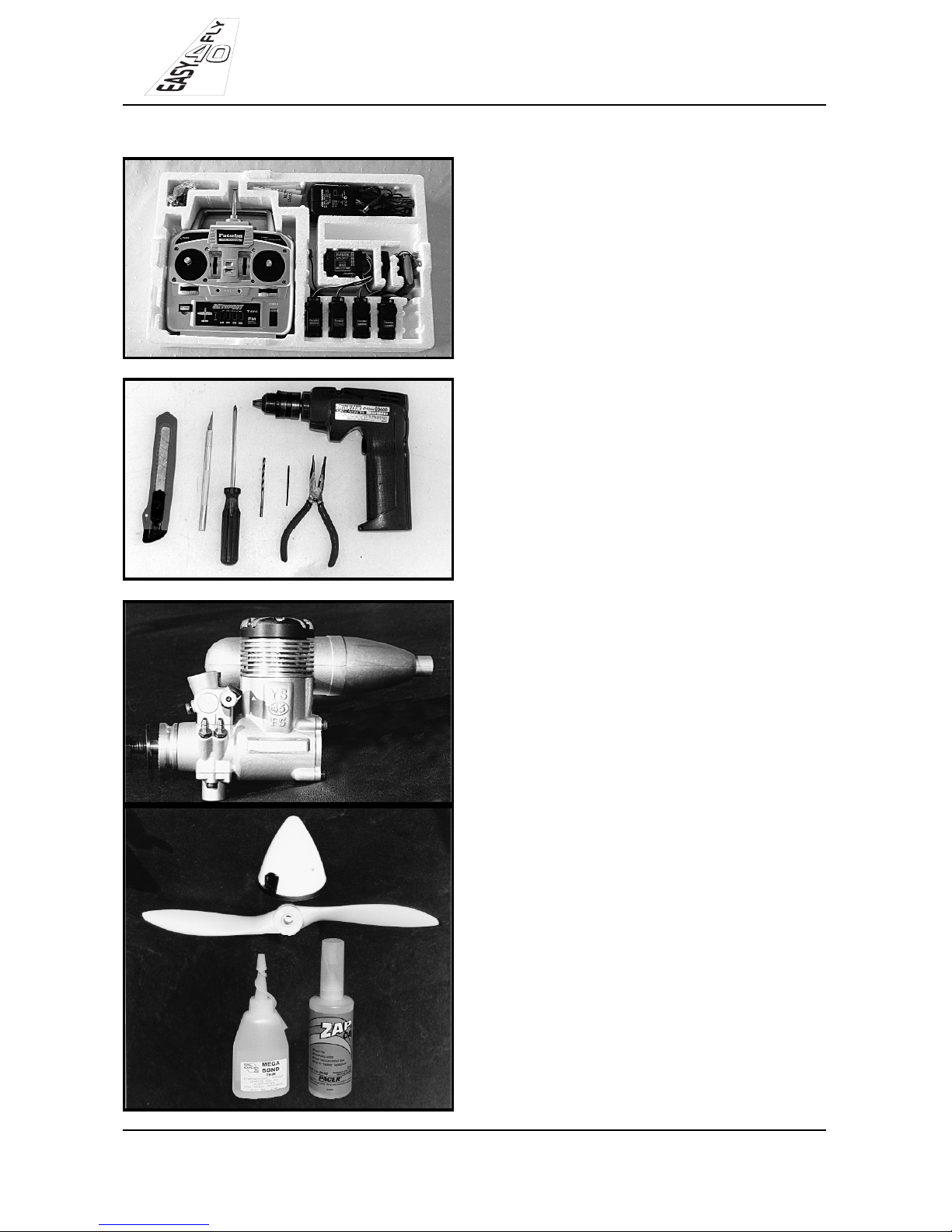
ADDITIONAL ITEMS REQUIRED
• RADIO
- Radio control unit with 4 or more channels
and 4 servos
• TOOLS REQUIRED
- Large knife
- No. 11 exacto knife
- Electric drill
- Phillips head screwdriver
- 2mm drill bit
- 3.5mm drill bit
- Pointy nose pliers
• ENGINE PROPELLER AND SPINNER
- Engine 40-46 Cu in 2 cycle
48-53 Cu in 4 cycle
- Propeller to suit engine
- Spinner (optional)
• THIN CA GLUE
• ALSO REQUIRED
- 30cm of silicone fuel line
- Piece if foam 30cmx30cm squared x13mm
thick
2
Page 3

INSTRUCTION MANUAL
EASY FLY 40
-Using No 11 knife, remove a small
amount of material from around the aileron
torque rods to allow 45 Deg. rearward and
forward movement.
-Detach aileron from the main wing panel.
-Using thin CA glue, fix hinges into aileron
-Fit aileron to main wing panel and using
thin CA glue fix hinges into wing panel.
3
DISTRIBUTED BY TATES PERFORMANCE HOBBIES Ph. 03-5222 7958
Wing Assembly
Page 4
INSTRUCTION MANUAL
EASY FLY 40
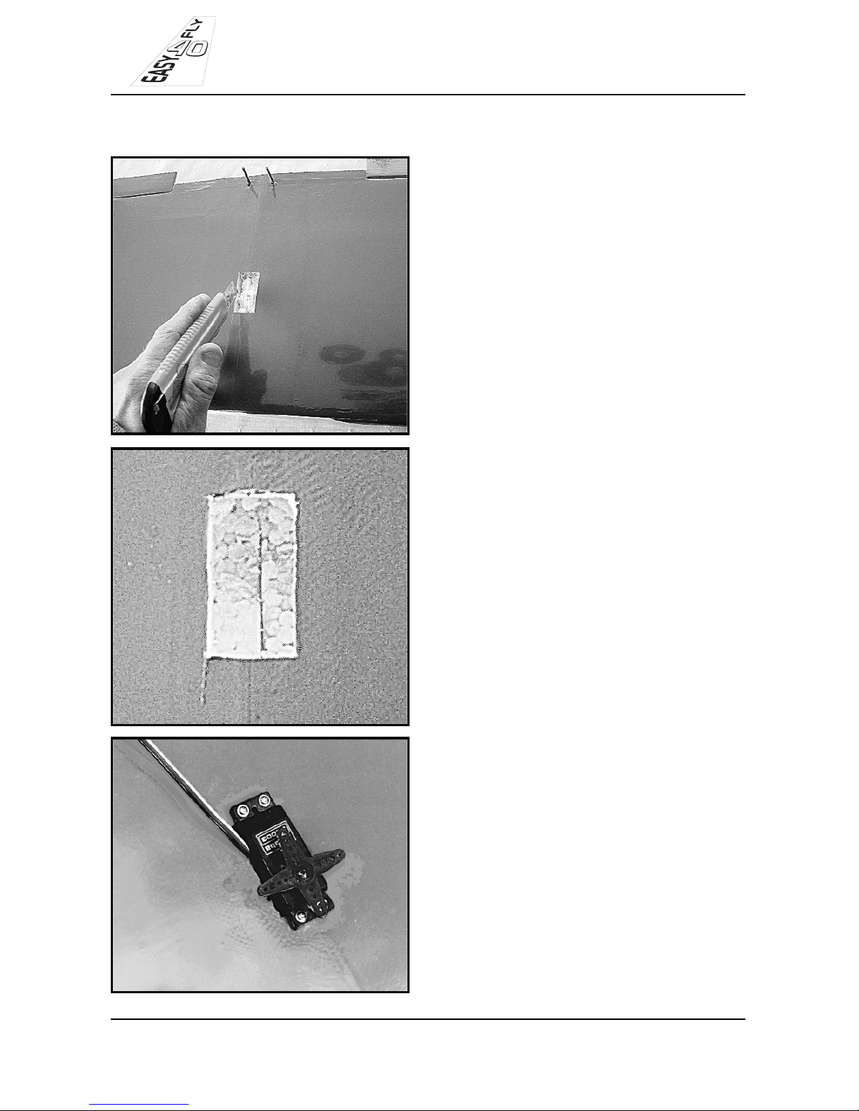
-Using a large knife, adjust the size of the
aileron hole to fit the aileron servo.
-Clear white foam from inside of the
aileron hole to allow the aileron servo to
fit inside the hole.
-Install the aileron servo into the servo
hole.
4
DISTRIBUTED BY TATES PERFORMANCE HOBBIES Ph. 03-5222 7958
Wing Assembly
Page 5
DISTRIBUTED BY TATES PERFORMANCE HOBBIES Ph. 03-5222 7958
INSTRUCTION MANUAL
EASY FLY 40
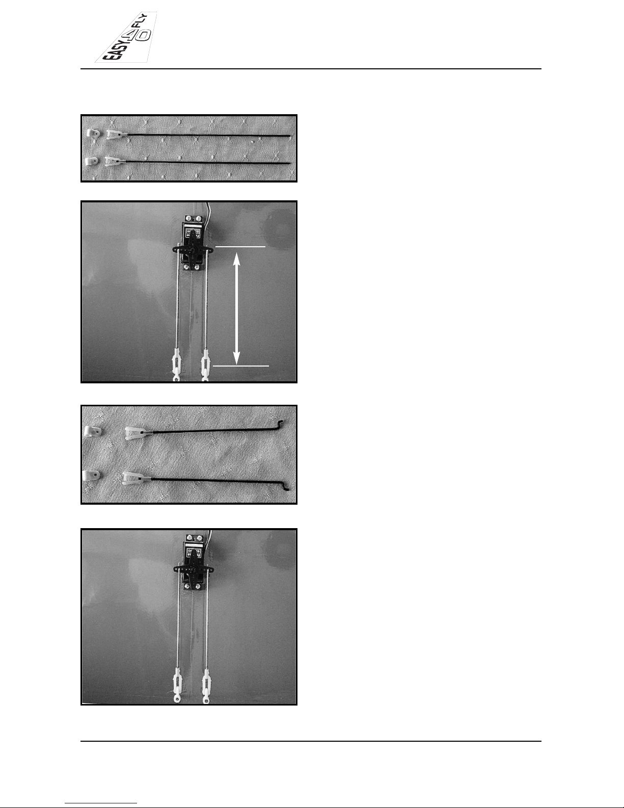
-Locate aileron pushrods in the kit.
-Measure distance from aileron servo arm
to aileron torque rods.
-Using pointy nose pliers, make a Z bend
in the unthreaded end of each pushrod,
to correspond to the distance measure
ment.
-Install aileron servo pushrods.
5
MEASURE
Wing Assembly
Page 6
INSTRUCTION MANUAL
EASY FLY 40
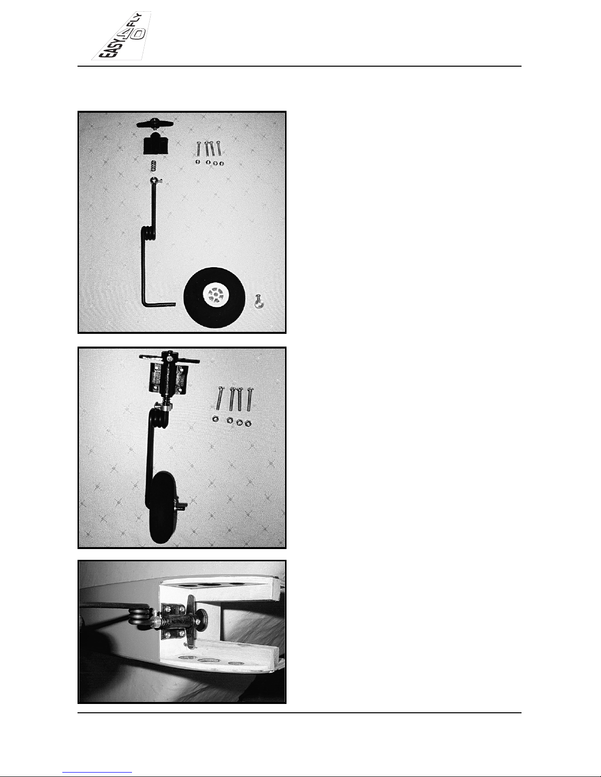
-Locate nose gear components in kit.
-Assemble nose gear as shown
-Bolt nose gear to the firewall using the 4
pre-drilled holes
-Drill a 3.5mm hole in the firewall for nose
wheel steering cable to exit.
-Install steering cable.
6
DISTRIBUTED BY TATES PERFORMANCE HOBBIES Ph. 03-5222 7958
Nose Installation
Page 7
DISTRIBUTED BY TATES PERFORMANCE HOBBIES Ph. 03-5222 7958
INSTRUCTION MANUAL
EASY FLY 40
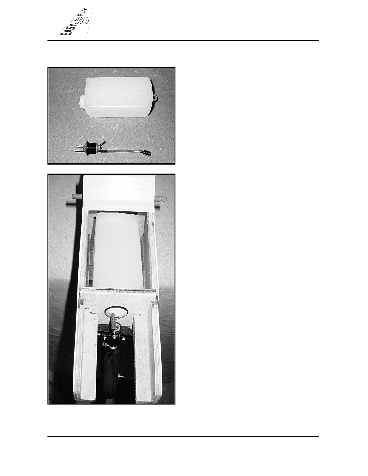
-Locate fuel tank pack and assemble the
stopper assembly as shown.
-Install fuel tank into fuselage.
-Pack 13mm thick foam around the fuel
tank. (Not shown in photo)
7
Fuel Tank Assembly
Page 8
INSTRUCTION MANUAL
EASY FLY 40
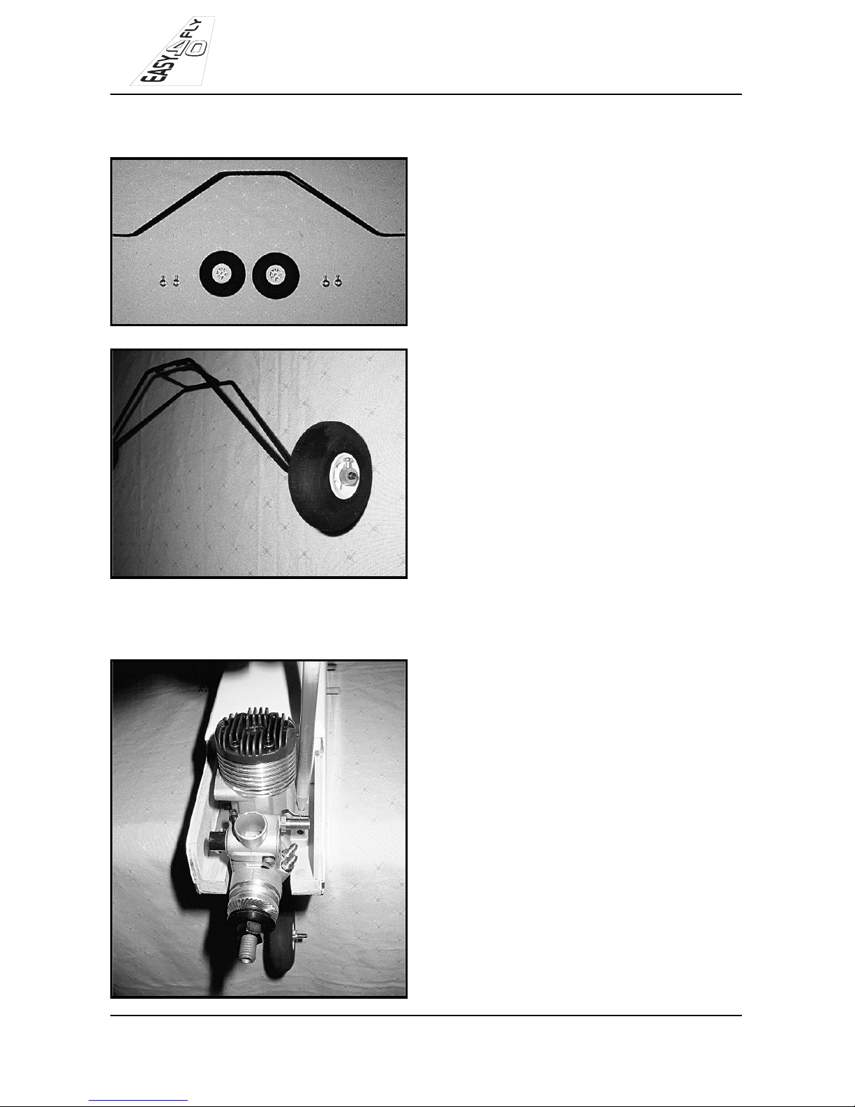
-Locate main undercarriage components
-Assemble main undercarriage, fixing a
wheel collar each side of the wheel.
8
DISTRIBUTED BY TATES PERFORMANCE HOBBIES Ph. 03-5222 7958
Main Undercarriage Installation
Engine Installation
-Place the engine between hardwood
bearers, and mark the position of the
holes.
-Then drill 4 pilot holes with 2mm-drill bit.
• Note – due to differing engine sizes, it
maybe necessary to adjust the width of
space between the two engine bearers.
Page 9
INSTRUCTION MANUAL
EASY FLY 40
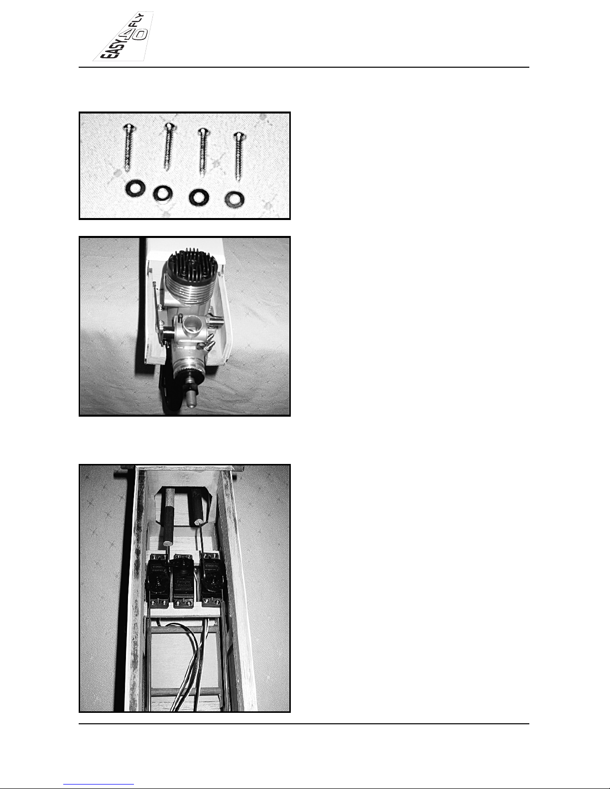
-Locate the 4 self-tapping screws and
washers in kit.
-Fix engine into fuselage using self-tap-
ping screws.
-Install throttle cable.
9
DISTRIBUTED BY TATES PERFORMANCE HOBBIES Ph. 03-5222 7958
-Install the rudder, elevator and throttle
servos into the fuselage.
• Note - because of differing servo sizes
the mounting beams may need to be
trimmed to allow servos to fit.
Servo Installation in Fuselage
Page 10
INSTRUCTION MANUAL
EASY FLY 40
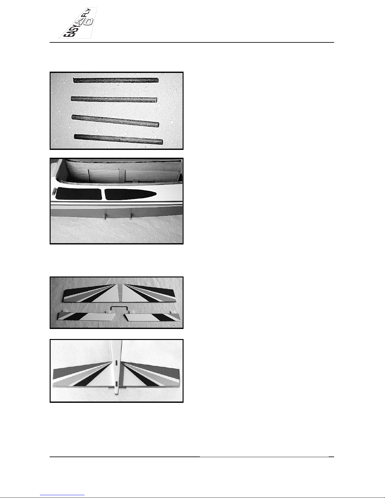
-Locate the 4 wing and main under car-
riage dowels in the kit.
-Locate the pre-drilled dowel mounting
holes beneath the film covering.
-Puncture film covering and install wing
and undercarriage dowels using CA glue.
10
DISTRIBUTED BY TATES PERFORMANCE HOBBIES Ph. 03-5222 7958
Wing and Undercarriage Dowels
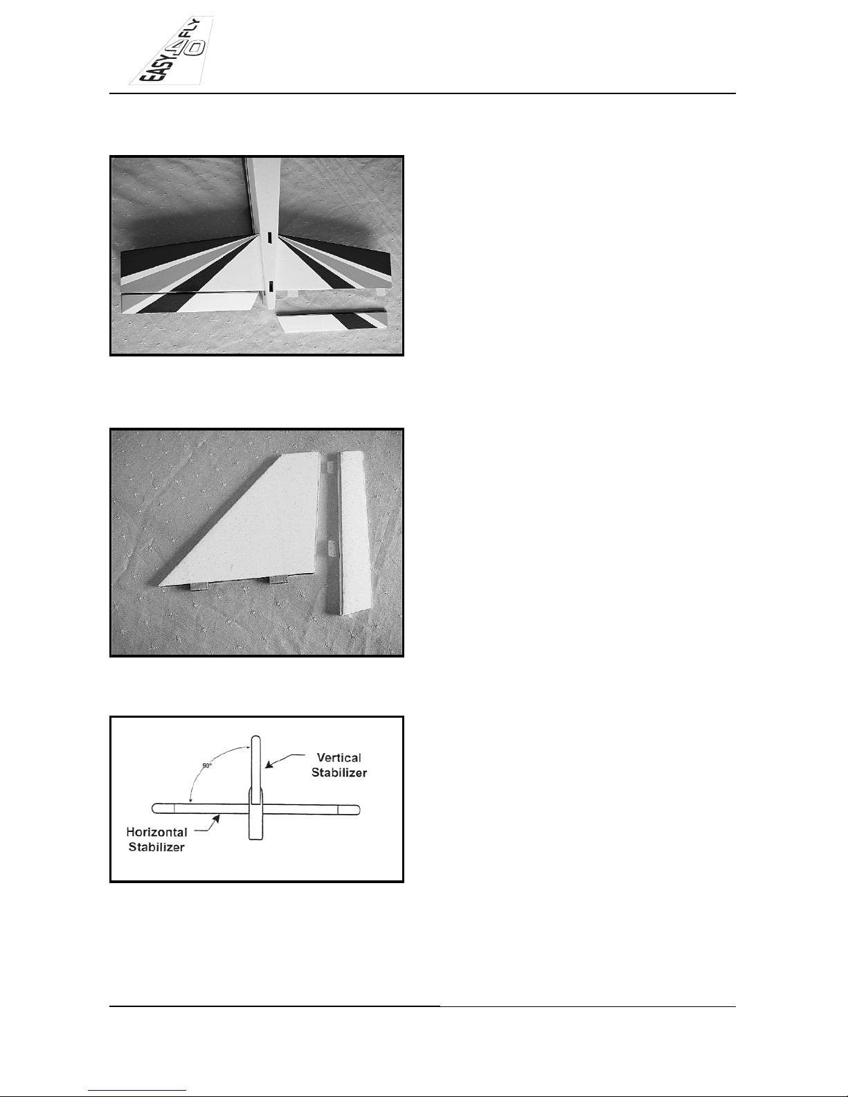
Horizontal Stabilizer
-Locate horizontal stabilizer and 3mm
steel elevator joining rod in the kit.
-Slide horizontal stabilizer into the slot
in the fuselage.
-Glue in place with CA glue.
** NOTE
-Ensure horizontal stabilizer is pushed
all the way forward in the slot.
-Ensure horizontal stabilizer is square
and centered in the fuselage before
gluing.
Page 11
INSTRUCTION MANUAL
EASY FLY 40
-Fit elevators to horizontal stabilizer and
3mm steel joining rod using CA glue.
Taking care to properly glue hinges.
11
DISTRIBUTED BY TATES PERFORMANCE HOBBIES Ph. 03-5222 7958
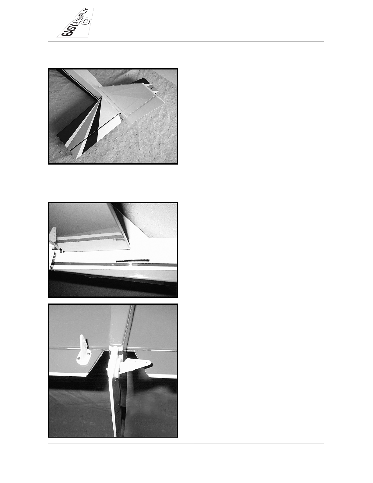
-Locate rudder and fin assembly in kit.
-Using thin CA glue, attach fin to rudder,
taking care to properly glue hinges.
-Slide fin and rudder assembly into place.
-Using a square, check to ensure the fin
and rudder are aligned 90 deg. to the
horizontal stabilizer.
Fin and Rudder Assembly
Page 12
INSTRUCTION MANUAL
EASY FLY 40
-Using thin CA glue, fix fin and rudder
assembly into place.
12
DISTRIBUTED BY TATES PERFORMANCE HOBBIES Ph. 03-5222 7958
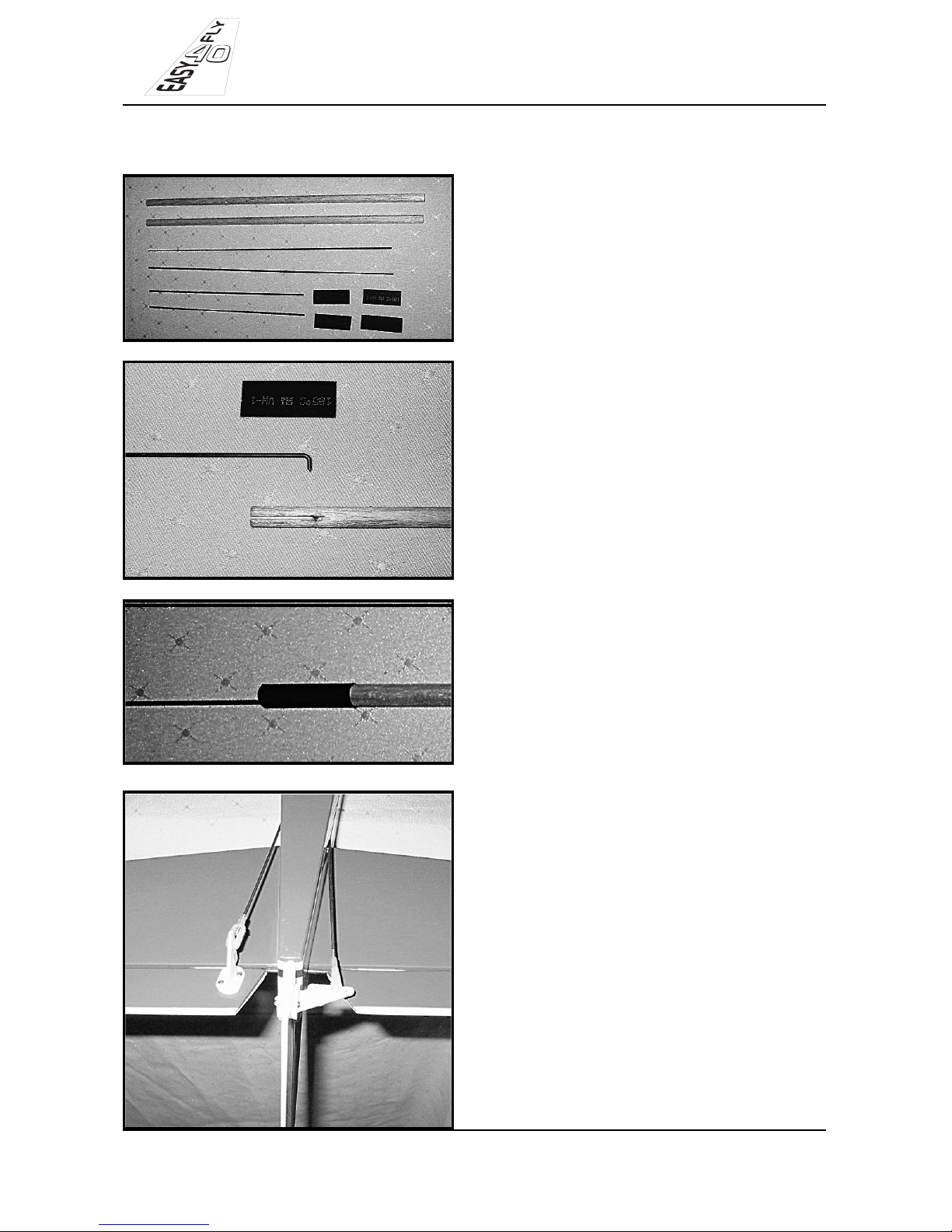
-Locate preformed elevator and rudder
pushrod exit slots beneath film covering
on both sides of the fuselage.
-Remove film covering with sharp knife.
*NOTE. It may be necessary to elongate
the pushrod exit slots to ensure smooth
pushrod operation.
-Locate rudder and elevator horns.
-Attach horns as shown, taking care to
align them with the pushrod exit slots in
the fuselage.
Pushrod and Control Horn Installation
Page 13
INSTRUCTION MANUAL
EASY FLY 40
-Locate pushrod components in kit.
*NOTE. The longer threaded wire rods
are for the rear of the pushrods.
-Make right angle bend in each pushrod
and assemble pushrod using black heat
shrink tubing.
-Completed pushrods.
*NOTE. Install the pushrods into the fuse-
lage before making the Z bends on the
servo end of the pushrod, to ensure correct pushrod length.
-Install pushrods into fuselage.
-Screw nylon clevice onto pushrod.
13
DISTRIBUTED BY TATES PERFORMANCE HOBBIES Ph. 03-5222 7958
Page 14
DISTRIBUTED BY TATES PERFORMANCE HOBBIES Ph. 03-5222 7958
INSTRUCTION MANUAL
EASY FLY 40
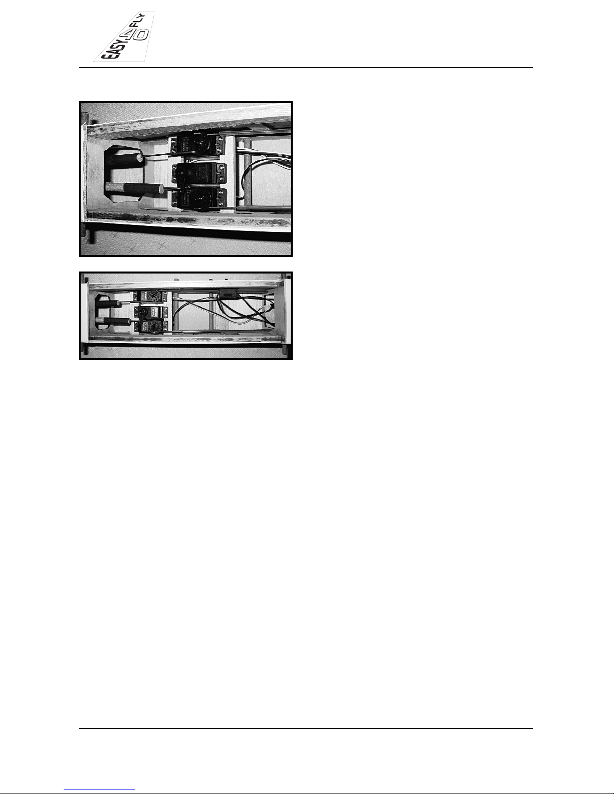
-Pushrods attached to servos.
-ON/OFF switch.
14
1. It is critical that your Easy Fly 40 is balanced correctly. Incorrect balancing may
cause loss of control and a crash. The
centre of gravity is located 9cm from the
leading edge of the wing. The Easy Fly
40 should be balanced with an empty fuel
tank.
2. Apply 2 pieces of masking tape to the
underside of the wing, and mark the centre of gravity on the tape ( 9cm from the
leading edge of the wing).
3. Place your fingertips on the marks
underneath the wing and carefully lift the
airplane.
4. If the tail falls, correct it by adding
weight to the front of the fuselage. If the
nose falls, correct it by adding weight to
the rear of the aircraft.
Centre of Gravity
Page 15

DISTRIBUTED BY TATES PERFORMANCE HOBBIES Ph. 03-5222 7958
INSTRUCTION MANUAL
EASY FLY 40
Control Throws.
Aileron - 10mm up and 10mm down
Elevator- 10mm up and 10mm down
Rudder- 20mm left and 20mm right
CONTROL SURFACE THROWS
The ailerons should move up 10mm and down 10mm. If the movement is excessive,
move the nylon clevice out one hole on the control horn until the control movement is
ideal.
The elevators should move up 10mm and down 10mm, again if the movement is excessive, move the nylon clevice out one hole on the control horn, away from the control surface.
The rudder should move left 20 mm and right 20mm, if the movement is not enough,
move the clevice in one hole closer on the control horn.
*NOTE. Pushrod clevices can sometime work loose on the metal pushrods, so it is recommended when all control surfaces throws have been set to the ideal, place a drop of
CA glue onto the metal pushrod thread to securely fix the nylon pushrod clevice into
place.
FLIGHT PREPARATION
Operation and Direction of the control surfaces.
- Turn on your radio transmitter.
- Then turn on your receiver.
(a) Check ailerons whilst standing behind the airplane, move the aileron stick to the right,
the right aileron should move up and the left aileron should move down. If not, then
switch the reversing switch on your transmitter.
(b) Check the elevator. Pull back on the elevator stick, the elevator should move up, then
push forward on the elevator stick, the elevator should now move down. If not then
switch the reversing switch on your transmitter.
(c) Check the rudder. Whilst standing behind the airplane move the rudder stick to the
right, the rudder should move to the right. If not switch the reversing stick on your
transmitter.
(d) Check the throttle. Push the throttle stick forward, the carburettor barrel should open
fully, without binding or excessively flexing the throttle cable, pull the throttle stick.
back and the carburettor barrel should close. If not then switch the reversing switch
on your transmitter.
15
Page 16
16
DISTRIBUTED BY TATES PERFORMANCE HOBBIES
PROBUILT
LOW FLY 40
ALSO AVAILABLE
 Loading...