

Page 1

5271.0008
V1
GB
Operating Instructions
Translation of original operating instructions
VACUUM-POWER-HANDY
VPH-150
Page 2

Contents
2 / 24
5271.0008
V1
GB
Contents
1 EC-Declaration of Conformity ............................................................................................................................... 4
2 Safety ...................................................................................................................................................................... 5
2.1 Safety symbols ................................................................................................................................................ 5
2.2 Explanation of basic concepts ....................................................................................................................... 5
2.3 Definition skilled worker / specialist .............................................................................................................. 5
2.4 Safety Marking ................................................................................................................................................ 6
2.5 Personal safety requirements ........................................................................................................................ 7
2.6 Protective equipment..................................................................................................................................... 7
2.7 Accident prevention ....................................................................................................................................... 7
2.8 Safety at work ................................................................................................................................................. 7
2.8.1 General ....................................................................................................................................................... 7
2.9 Function Control ............................................................................................................................................. 8
2.9.1 General ....................................................................................................................................................... 8
2.9.2 Electric ........................................................................................................................................................ 8
3 General .................................................................................................................................................................... 9
3.1 Authorized use ................................................................................................................................................ 9
3.2 Survey and construction ............................................................................................................................... 11
3.3 Technical data ................................................................................................................................................ 11
4 Installation ............................................................................................................................................................. 12
4.1 Mechanical connection ................................................................................................................................. 12
4.1.1 Lifting eye / Suspension bolt .................................................................................................................... 12
4.1.2 Load hook and chains ............................................................................................................................... 12
4.2 Assembly of the Wheel Set VPH-RS .............................................................................................................. 12
4.3 Assembly of Stop for Wheel Set VPH-RS-AS ................................................................................................ 13
5 Adjustments .......................................................................................................................................................... 14
5.1 Adjustment of VPH and the assembly ..........................................................................................................14
6 Operation .............................................................................................................................................................. 15
6.1 Operating Elements ....................................................................................................................................... 15
6.2 Suction Plate .................................................................................................................................................. 15
6.3 General ........................................................................................................................................................... 15
6.4 Battery ............................................................................................................................................................ 15
6.5 Lifting, Transport and Installation (hoist operation) .................................................................................. 16
6.6 Lifting, Transport and Installation (manual operation) ............................................................................... 17
6.7 Tile laying ....................................................................................................................................................... 17
6.8 Damages of suction plate ............................................................................................................................. 18
7 Maintenance and care .......................................................................................................................................... 18
7.1 Maintenance ................................................................................................................................................. 18
7.1.1 Mechanical .................................................................................................................................................... 18
7.2 Suction plate ................................................................................................................................................. 19
7.3 Fault finding .................................................................................................................................................. 19
7.4 Repairs .......................................................................................................................................................... 20
7.5 Safety procedures ........................................................................................................................................ 20
7.6 Hints to the type plate ................................................................................................................................... 21
7.7 Hints to the renting/leasing of PROBST devices .......................................................................................... 21
Page 3

EC-Declaration of Conformity
3 / 24
5271.0008
V1
GB
8 Vacuum pump ...................................................................................................................................................... 22
8.1 General .......................................................................................................................................................... 22
8.2 Safety Advice ................................................................................................................................................ 22
8.3 Description .................................................................................................................................................... 22
8.3.1 Charge battery ......................................................................................................................................... 23
8.4 Maintenance ................................................................................................................................................. 23
8.5 Technical Data ............................................................................................................................................... 24
Page 4

EC-Declaration of Conformity
4 / 24
5271.0008
V1
GB
1 EC-Declaration of Conformity
Description:
Type:
Order number:
VACUUM-POWER-HANDY
VPH-150
5271.0008
Manufacturer:
Probst GmbH
Gottlieb-Daimler-Straße 6
71729 Erdmannhausen, Germany
info@probst-handling.de
www.probst-handling.de
The machine described above complies with the relevant requirements of the following EU directives:
EC-machinery directive 2006/42/EC
2014/30/EU (Electromagnetic compatibility)
The following standards and technical specifications were used:
DIN EN ISO 12100
Safety of machinery - General principles for design - Risk assessment and risk reduction (ISO 12100:2010)
DIN EN ISO 13857
Safety of machinery - safety distances to prevent hazard zones being reached by upper and lower limbs (ISO 13857:2008)
DIN EN 1012-1 / DIN EN 1012-2
Compressors and vacuum pumps; Safety requirements part 1 and 2.
DIN EN 60204-1 (IEC 60204-1)
Safety of machinery, electrical equipment of industrial machines. Part 1: General requirements.
Authorized person for EC-documentation:
Name: J. Holderied
Address: Probst GmbH; Gottlieb-Daimler-Straße 6; 71729 Erdmannhausen, Germany
Signature, information to the subscriber:
Erdmannhausen, 11.07.2018..........................................................................
(M. Probst, Managing director)
Page 5

Safety
5 / 24
5271.0008
V1
GB
2 Safety
2.1 Safety symbols
Danger to life!
Identifies imminent hazard. If you do not avoid the hazard, death or severe injury will result.
Hazardous situation!
Identifies a potentially hazardous situation. If you do not avoid the situation, injury or damage to property
can result.
Prohibition!
Identifies imminent a prohibition. If you do not avoid the prohibition, death and severe injury, or damage to
property will result.
Important information or useful hints for the usage.
2.2 Explanation of basic concepts
Gripping range:
specify the minimum and maximum product measurements of the gripping good, which
can be gripped with this device.
Gripping good(s):
is the product, which will be gripped or transported.
Opening width:
consists of the gripping range and the measure to drive over the gripping good.
gripping range + measure to drive over the gripping good = opening width
Immersion depth:
is the maximum gripping height of gripping goods, conditional of the height of the
gripping arms of the device.
Device:
is the description for the gripping device.
Product dimensions:
Are the dimensions of the gripping good (e.g. length, breadth, height
of the product).
Dead weight:
is the own weight (without gripping good) of the device.
Carrying capacity/working
load limit (WLL*):
specify the maximum possible load of the device (for lifting of gripping goods).
2.3 Definition skilled worker / specialist
Only skilled workers or specialists are allowed to carry out the installation-, maintenance-, and repair work on this device!
Skilled workers or specialists must have for the following points (if it applies for this
device), the necessary professional knowledge.
for mechanic
for hydraulics
for pneumatics
for electrics
*= WLL (english:) Working Load Limit
Page 6

Safety
6 / 24
5271.0008
V1
GB
2.4 Safety Marking
PROHIBITION SIGN
Symbol
Meaning
Order-No.
Size
It is not allowed to stand under hanging loads. Danger to life!
2904.0210
2904.0209
2904.0204
Ø30 mm
Ø50 mm
Ø80 mm
Working with this device is only permitted in proximity to the
ground.
The sucked load must never be lifted more than 1.8 m
(measured from the top edge of the load to the ground).
Swinging the device over persons is prohibited.
2904.0765
100 x70 mm
WARNING SIGN
Symbol
Meaning
Order-No.
Size
Danger of squeezing the hands.
2904.0221
2904.0220
2904.0107
30 x 30 mm
50 x 50 mm
80 x 80 mm
REGULATORY SIGN
Symbol
Meaning
Order-No.
Size
Each operator must have read and understood the operating
instructions (and all safety instructions).
2904.0665
2904.0666
Ø30 mm
Ø50 mm
Loads have to be sucked in centered. With a suitable device (height
adjustable stop) loads can also be sucked in eccentrically.
2904.0744
107 x 32 mm
Safety chains has to fit tightly to the load.
Safety chains should never hang loosely under the load!
2904.0690
2904.0689
2904.0688
25 x 55 mm
70 x 41 mm
146 x 85 mm
OPERATING INFORMATIONS
Symbol
Meaning
Order-No.
Size
Maximum working load limit of the suction plate (VPH-100)
2904.0575
80 x 40 mm
Maximum working load limit of the suction plate (VPH-150)
2904.0207
80 x 35 mm
Label with device title
2904.0129
200 x 50
mm
Page 7
Safety
7 / 24
5271.0008
V1
GB
2.5 Personal safety requirements
Each operator must have read and understood the operating instructions (and all safety instructions).
Only qualified, authorized personal is allowed to operate the device and all devices which are connected
(lifting device/carrier).
The manual guiding is only allowed for devices with handles.
2.6 Protective equipment
The protective equipment must consist, according to the safety regulations
of the following parts:
Protective clothing
Safety gloves
Safety shoes
2.7 Accident prevention
The workplace has to be covered for unauthorized persons, especially children.
Take care in case of thunderstorm!
The workplace has to be sufficiently illuminated.
Take care with handling wet, dirty and not solidified components.
The working with the device in case of atmospheric editions under 3 °C (37,5 °F) is forbidden!
Because the goods could be fall down caused by dampness or freezing.
2.8 Safety at work
2.8.1 General
Working with this device is only permitted in proximity to the ground.
The sucked load must never be lifted more than 1.8 m (measured from the top edge of the load to the
ground). Swinging the device over persons is prohibited. Danger to life!
The manual guiding of is only allowed for devices with handles.
The operator is not allowed to leave the control unit as long as the vacuum lifting device loaded with
load (stone slab). The load must always be in the range of vision of the operator.
Always keep an eye on the vacuum gauge. Never lift loads when the vacuum is below the required under
pressure (mbar). If the pointer of the pressure gauge moves into the red danger zone, lower the load
immediately! Danger! Load could fall down!
Page 8
Safety
8 / 24
5271.0008
V1
GB
While using the vacuum lifting device is the stay of persons in the working area forbidden. Except it is
indispensable. Caused of the way of using the vacuum lifting device , e.g. if the device must be leaded by
hand.
While using the vacuum lifting device be sure that there are no persons in the working area. Danger to
Life!!
The device must never be subjected to a force acting in a lateral direction due to diagonal pulling.
Do not lift any components off-centre, because that could fall down. Danger of tilting!
Release the load only when it is completely safely resting on the surface. Keep fingers away from the
load when you release it as they can be crushed!
The carrying capacity / working load limit (WLL) and the nominal width the vacuum lifting device must
not be exceeded.
Do not pull out stuck or tightened loads with the device.
The jerky raising or lowering of the device with or without load is prohibited!
Unnecessary vibrations must be avoided. Just like driving fast with the carrier/ hoist over uneven terrain!
Danger to life: Load could fall off or load handling equipment could be damaged!
In general, only drive at walking speed with the load lifted!
2.9 Function Control
2.9.1 General
Before using the device check the functions and the working condition.
Maintenance and lubrication are only permitted when device is shut down!
Do not use the device, until all faults which can cause safety hazards are removed.
If there are any cracks, splits or damaged parts on any parts of the device, immediately stop using it.
The operating instructions must be available at the workplace every time.
Do not remove the type plate of the machine.
Unrecognisable information signs (such as regulatory or prohibition signs) must be replaced.
2.9.2 Electric
Check all electric cables for connection
Defective electrical parts may be exchanged only by qualified personnel in the dead condition.
The electric cables must be free of breaks and abrasion. Take care that there are no outstanding
edges, where the hoses could get stuck.
Page 9
General
9 / 24
5271.0008
V1
GB
3 General
3.1 Authorized use
The device “VACUUM-POWER-HANDY VPH” is only for lifting, transporting and installing natural stone and concrete slabs,
large slabs, drain joint stones, steps, as well as tiles in close proximity to the ground. The goods to be lifted must have no
porous surfaces.
The device is equipped with a suspension lug for crane hook.
The stated maximum load can only be achieved with a vacuum of at least 500 mbar!
The device can only be used in a vertical hanging.
Some of the suction plates, which can be attached to the device, reduce its carrying capacity.
The working load limit (WLL) is stated on each suction plate.
Never exceed the working load limit!
Without additional accessoires the device has to pe operated by two persons.
With suitable equipment the device can be operated by one person.
For more information see Chapter “Survey and construction”.
The device is only designed for the use specified in this documentation.
Every other use is not authorized and is forbidden!
All relevant safety regulations, corresponding legal regulations, especially regulations of the declaration
of conformity, and additional local health and safety regulations have to be observed.
Prior to every operation the user must ensure that:
The equipment is suited to the intended operation, the functioning and the working condition of the
equipment is examined, and the load is suitable to be handled.
Any doubts about instructions should be raised with the manufacturer prior to use.
ATTENTION: The use of this device is only permitted in proximity to the ground ( chapter “Safety at
work”)
Page 10
General
10 / 24
5271.0008
V1
GB
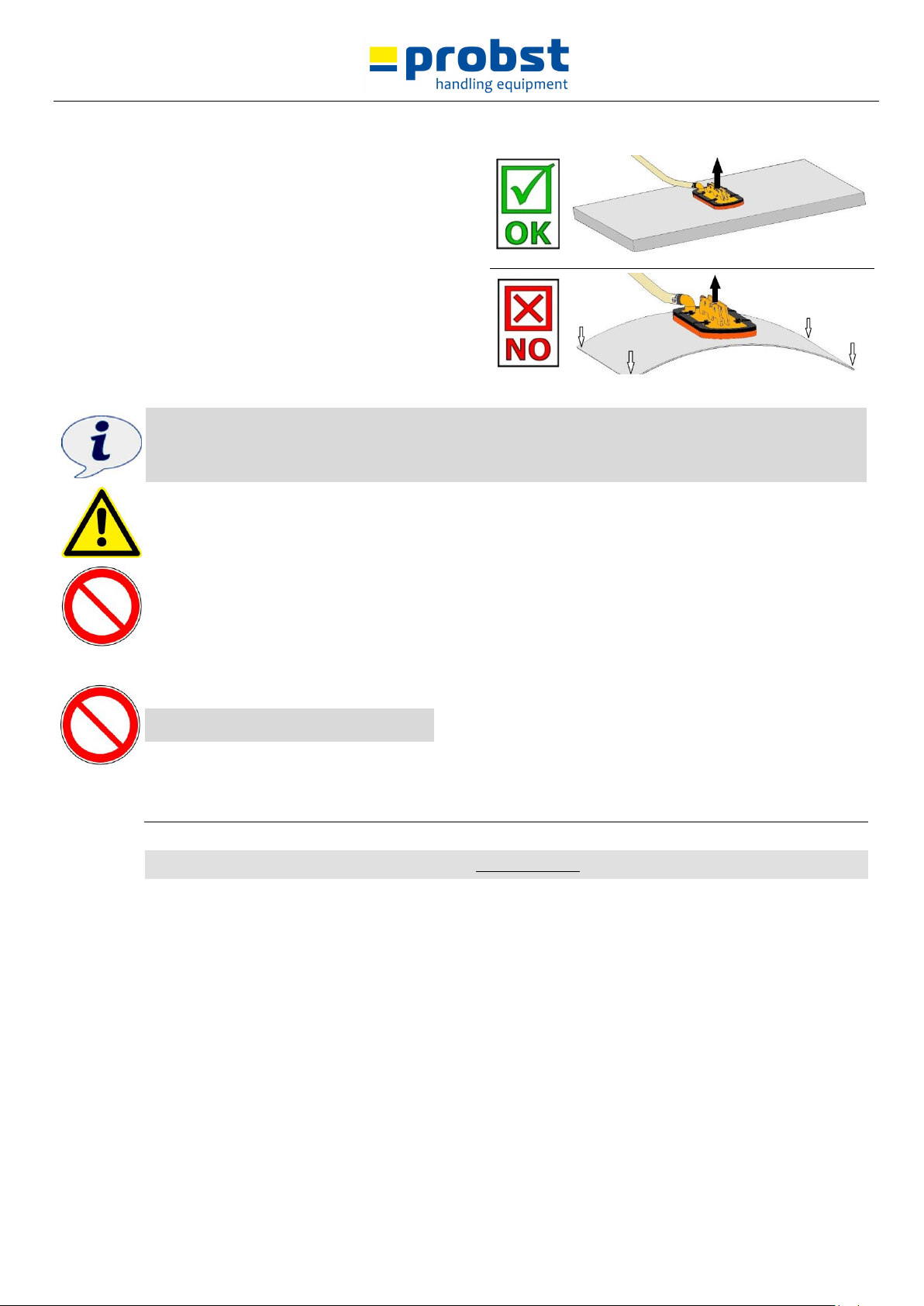
The load (stone slabs) which is to be sucked and
transported, must have sufficient inherent stability,
otherwise there is risk of breakage when lifting!
Stone slabs must not be bend when lifting - especially take
care with thin and large-sized stone slabs!
Generally, the load (stones slab) is only to be sucked in the
middle, otherwise the load hangs diagonally under the
device and the load could break - especially when lifting
large stone slabs with a small suction plate.
Standard suction plates are not suitable for the transport of
glass plates!
Only suction plates of the manufacturer PROBST shall be used!!!
Some suction plates which can be mounted to the device will reduce its carrying capacity.
The maximum load is indicated on each suction plate.
Use only suction plates which are approved for this device!
Do not exceed the maximum carrying capacity of the suction plates!
Danger: Load (stone slabs) will fall down!
NOT ALLOWED ACTIVITIES:
Unauthorized alterations of the device and the use of any self-made additional equipment could cause
danger and are therefore forbidden!
Never exceed the carrying capacity and the nominal width/nominal size of the device.
All unauthorized transportations with the device are not allowed:
Transportation of people and animals.
Transportation of other loads and materials than described in this manual.
Never suspend any goods with ropes, chains or similar at the device.
Page 11

General
11 / 24
5271.0008
V1
GB
3.2 Survey and construction
1
2
3
4
5
8
6
7
10
9
1. Handle
2. Lifting eye
3. Battery-adapter cable with terminals
4. Vacuum pump
5. Pressure gauge
6. Air filter
7. Chain box
8. Suction plate
9. Wheel Set VPH-RS, allow to use the device by one person (optionally)
10. Stop for Wheel Set VPH-RS-AS, for large-size tiles (optionally)
3.3 Technical data
Type
Carying capacity/WLL [kg] valve at 500 mbar under-pressure
Dead weight [kg]
VPH-150
150
19,5
Page 12

Installation
12 / 24
5271.0008
V1
GB
4 Installation
4.1 Mechanical connection
Use only original accessories, in case of doubt consult the manufacturer.
Take care that the carrying capacity / working load limit (WLL) of the lifting device/carrier is not exceeded,
through the load of the device, the attaching devices (turning device, fork sleeves etc.) and the additional
load of the gripping goods!
Mechanical gripping devices always have to be gimballed, so they can swing freely in any position.
In no case it is allowed to mount mechanical gripping devices with lifting devices/carriers in a rigid way!
Break of the suspension may occur within short time. Death, severe injuries and material damage can
result!
4.1.1 Lifting eye / Suspension bolt
The device is equipped with a lifting eye / suspension bolt and can be mounted on various carrier /
lifting devices.
Take care that the lifting eye / suspension bolt is safely joined with the lifting tackle (e.g. crane hook,
belt) and cannot slide down.
4.1.2 Load hook and chains
Fit suspension ring in the load hook of the lifting device/carrier.
Ensure that the single chains strands are not twisted or knotted.
Attaching the device to the lifting device/carrier, take care that all local safety regulation is observed.
4.2 Assembly of the Wheel Set VPH-RS
Page 13

Installation
13 / 24
5271.0008
V1
GB
4.3 Assembly of Stop for Wheel Set VPH-RS-AS
Page 14

Adjustments
14 / 24
5271.0008
V1
GB
5 Adjustments
5.1 Adjustment of VPH and the assembly
Page 15

Operation
15 / 24
5271.0008
V1
GB
6 Operation
6.1 Operating Elements
Main switch –on / off. This is to turn the pump on and off.
Caution! The suction guide line is automatically bled when the VPH is switched off.
For a description of the other elements, please refer to the Appendix: Operating Instructions for the Battery
Diaphragm Pump!
To suction and release the load:
Main Switch ON = suction load, hold
Main switch OFF = release load (remove feet from danger area beforehand!)
6.2 Suction Plate
The suction plate brings the vacuum onto the load. It is used to lift various objects.
Only use suction plates intended for the VPH.
Never exceed the permitted maximum carrying capacity of the suction plate!
6.3 General
Do not let go off the handle of the device VPH whilst a load is being lifted.
Never pull the load diagonally or drag it.
Do not try to free loads which are stuck using the VPH.
If there is a power failure, put down the load straight away if possible. Move away from the danger area
immediately.
Only suction and lift suitable loads (Check for stability and surface density).
Always keep an eye on the pressure gauge. Never lift a load under - 0,5 bar. If the pointer in the pressure
gauge moves into the red zone below - 0,5 bar, put down the load immediately.
Set down the goods on clear, even surfaces only. Otherwise they could slip when released.
Only release the load when it is fully and securely standing or lying down.
Keep your fingers away from the load when relevant it to prevent them from being crushed!
Always load the suction plates evenly.
6.4 Battery
LED-board:
yellow = charged completely
green = normal status
red-green changing = battery low, charge
red = do not use, battery is empty
Page 16

Operation
16 / 24
5271.0008
V1
GB
6.5 Lifting, Transport and Installation (hoist operation)
When using the device in hoist operation the safety chain has to be used in any case!
1. Position the device directly above the load. Avoid pulling it diagonally, make
sure the load is evenly distributed.
2. Place the device onto the load.
3. Switch the device on using the main ON / OFF switch.
4. The load is now sucked.
5. Look at the pressure gauge. As soon as a vacuum of -0.5 bar is reached, you can
lift the load. On no account lift it earlier, as the load would fall off.
When lifting, make sure that only one part at a time is being lifted! Carefully
release any bits left hanging on with a screwdriver before lifting the load any
further.
Do not remove any bits with your hands, risk of crushing!
6. Lift the device with the sucked load a little (approx. 20 cm).
7. Put the safety chain A out of the chain box B (see Ill.)
8. Throw the safety chain under the lifted load.
In doing so never reach you hands under the lifted load! Danger of crushing!
9. Firmly mount the safety chain on the other side of the device in the slot C (see Ill.).
10. Place the end of the safety chain in the chain box B.
The safety chain has to fit tightly on the load, to make sure, that the load will be held by the
safety chain in case of vacuum loss or vacuum failure (e.g. caused by energy failure), (see
Ill.).
The load-securing chain should never hang loosely under the load, otherwise the load
could fall down in case of vacuum loss or vacuum failure (e.g. caused by energy failure),
(see Ill.).
11. Now transport the device with the sucked load to the destination point.
12. Carefully lower the load (approx. 20 cm to the ground), unhook the safety chain and pull it out from under the
load.
In doing so never reach you hands under the lifted load! Danger of crushing!
13. Put the load-securing chain back in the chain box.
14. Lower the load and place it on clear, even surfaces, so that the load does not slip or tip.
15. Switch off the diaphragm pump using the main ON / OFF switch.
Page 17

Operation
17 / 24
5271.0008
V1
GB
Caution! Once the machine is switched off, the suction lead is automatically bled and so the vacuum
disappears. Always keep feet well away from the danger area!
6.6 Lifting, Transport and Installation (manual operation)
1. Position the device directly above the load. Avoid pulling it diagonally, make sure the load is evenly distributed.
2. Place the device onto the load.
3. Switch the device on using the main ON / OFF switch.
4. The load is now sucked.
5. Look at the pressure gauge. As soon as a vacuum of -0.5 bar is reached, you can lift the load. On no account lift it
earlier, as the load would fall off.
When lifting, make sure that only one part at a time is being lifted! Carefully release any bits left hanging on with a
screwdriver before lifting the load any further.
Do not remove any bits with your hands, risk of crushing!
6. Now transport the device with the sucked load to the destination point.
7. Lower the load and place it on clear, even surfaces, so that the load does not slip or tip.
8. Switch off the diaphragm pump using the main ON / OFF switch.
Caution! Once the machine is switched off, the suction lead is automatically bled and so the vacuum
disappears. Always keep feet well away from the danger area!
6.7 Tile laying
Recommended device configuration:
VPH basic device+
VPH-RS wheel set+
VPH-RS-AS, height adjustable stop, to put the tile in different angle positions, tilted to the front.
Example for tile laying
Only with the height adjustable stop VPH-RS-AS loads can be sucked in eccentrically.
Otherwise the load can become detached or break!
Page 18

Maintenance and care
18 / 24
5271.0008
V1
GB
6.8 Damages of suction plate
Avoidance of damages:
To avoid damages of the rubber seal on the suction plate (chinks, abrasion) take notice, that:
during the operation (lifting, transporting and lowering) with the device, the suction plate does not brush or pump
against other products or materials.
Otherwise the rubber seal on the suction plate could be damaged (danger of pressure loss).
Product could fall down. Danger of accidents!
7 Maintenance and care
7.1 Maintenance
To ensure the correct function, safety and service life of the device the following points must be executed in
the maintenance interval.
Used only original spare parts, otherwise the warranty expires.
All operations may only be made in unpressurised, electro less and closed state of the device!
7.1.1 Mechanical
SERVICE INTERVAL
Maintenance work
First inspection after
25 operating hours
Control and tighten all screws and connections.
(The implementation is only allowed by an expert).
All 50 operating hours
Tighten all screws and connections (take care that the tightening torques according to
the property class of the screws are observed).
Check all existing safety elements (such as linchpins) for perfect function and replace
defective safety elements. 1)
Check all joints, bolts, guidance’s and gears for correct function, if necessary adjust or
replace it.
Check all grippers (if available) for signs of wear.
Grease all slidings (if available) when the device is in opened position with a spatula.
Grease all grease nipples (if available) with a grease gun.
Minimum 1x per year
(at rough conditions shorten the
interval)
Check of all the suspension parts, bolts and straps. Check for corrosion and safety by an
expert.
1)
Page 19

Maintenance and care
19 / 24
5271.0008
V1
GB
7.2 Suction plate
Clean the sealing lips with compressed air and/or water jet once per week to remove any objects and dirt
such as sand, stone particles, dust etc. Clean slot in the sealing lip with a cloth and / or blow out with
compressed air.
(If applicable): Clean the groove in the sealing lip with a wipe and/or blow out with compressed air.
Damaged or worn sealing lips (cracks, holes, deformation) must be replaced immediately.
Use only cold solvent for cleaning the device. Do not use benzene or caustic liquids, since these will
damage the hoses.
7.3 Fault finding
Fault
Cause
Remedy
A vacuum of - 0,5 bar cannot be
achieved.
The item to be lifted has splits, recesses
or is porous.
The item is not suitable to be lifted with the
device
The foam rubber is damaged.
Replace the foam rubgber.
The pressure gauge is faulty.
Replace the pressure gauge.
The hose ors screws are leaky.
Replace the relevant parts.
VPH just wont work/ or no
Vacuum available
Battery
Check the battery is fully charged
value
Check the fuse is of the correct value ( 8amp )
and is not blown
seal
Check the seal around baseplate, if possable
remove the seal and clean around the edge of
the plate, and in the groove of the seal, but do
not glue the seal on.
vacuum pipe
Check the fitting that interfaces the vacuum
pipe to the plate and check that it is fully
tightened and has not come loose.
air filter and the fittings
Check the air filter and the fittings such as pipe
clips etc, and make sure they are tightly sealed.
ON / OFF switch
Make absolutely sure that the ON / OFF switch
is working ok.
wires on solinoid valve
Check the wires on the solinoid valve are
connected ok.
short circuit on solinoid
Check the diode on the solinoid ( 1N4001 etc )
has not gone short circuit, you can remove this
completely or just cut it out, Do not replace this
component
pipes to the vacuum pumps
Check all pipes to the vacuum pumps are not
damaged.
foreign bodies
Check that there is a vacuum or pressure on the
pumps and that they have not been damaged
by the ingression of foreign bodies.
Page 20

Maintenance and care
20 / 24
5271.0008
V1
GB
Load cannot be sucked.
Prescribed negative pressure
cannot be achieved no more.
Negative pressure diminishes
itself too fast, when switching
the device off.
Leakage at vacuum plate by deposited
dirt between rubber seal and suction
plate.
Rubber seal wore or porously (aging
after effect of UV radiation)
Remove rubber seal from suction plate.
Clean suction plate and slot in rubber seal.
Draw up and fasten rubber seal on suction plate
again.
If necessary exchange rubber seal.
7.4 Repairs
Only persons with the appropriate knowledge and ability are allowed to repair the device.
Before the device is used again, it has to be checked by an expert.
7.5 Safety procedures
It is the contractor’s responsibility to ensure that the device is checked by an expert in periods of
max. 1 year and all recognized errors are removed ( see BGR 500).
The corresponding legal regulations and the regulations of the declaration of conformity have to be
observed!
We recommend that after checking the device, the badge “Safety checked” is put on the device.
(Order-No.: 2904.0056+inspection sticker with date).
You can receive these badges from us.
The check by an expert must be proved!
Device
Year
Date
Expert
Company
Page 21

Maintenance and care
21 / 24
5271.0008
V1
GB
7.6 Hints to the type plate
Type, serial-number and production year are very important for the identification of your device. If you need
information to spare-parts, warranty or other specific details please refer to this information.
The maximum carrying capacity/working load limit (WLL) is the maximum load which can be handled with
the device. Do not exceed this carrying capacity/working load limit (WLL).
If you use the device in combination with other lifting equipment (Crane, chain hoist, forklift truck,
excavator) consider the deadweight of the device.
Example:
7.7 Hints to the renting/leasing of PROBST devices
With every renting/leasing of PROBST devices the original operating instructions must be included
unconditionally (in deviation of the users country's language, the respective translations of the original
operating instructions must be delivered additionally)!
Page 22

Vacuum pump
22 / 24
5271.0008
V1
GB
8 Vacuum pump
8.1 General
This vacuum pump is equipped with a rechargeable 12 Volt 6.5 Ah lead battery, and the pump is powered by an in-built lead
battery.
The recharging control system lets you see how charged up the battery is.
8.2 Safety Advice
The voltage must comply with that stated on the vacuum pump data plate. The pump must only be powered by a 12
Volt direct current.
Before working on the pump, including changing the supply hose, remove the plug from the socket.
The lead wires have to be in perfect condition. Any damaged parts have to be replaced immediately.
Only use original spare parts.
Do not plug in the pump to the mains if it is raining or damp.
When opening covers or removing parts, except for when this can be done by hand, live parts can be exposed.
Connections can also be live.
Before carrying out any maintenance work, repairs or replacing any parts, the pump must be disconnected from all
power sources if it needs to be opened.
Do not use the pump in rooms or in surroundings in which gases, fumes or dust are present or could be present.
Protect the device for wetness and dampness.
Do not use the pump if safe working conditions cannot be guaranteed. It would not be safe to continue if:
The pump is clearly damaged.
The pump no longer works.
It has been stopped for a long period or in unfavourable conditions.
It is damaged during transportation.
Never switch the pump on straight away if it is brought in from a cold room to a warm one.
The condensation could damage your pump. Let it come to room temperature without switching it on.
8.3 Description
The pump consist of the following parts:
Robust aluminium casing with a mounting to fix it onto the Probst stand.
Two 12 Volt diaphragm pumps.
Main switch – on / off function – using the main switch you can switch the pump on or off. By switching it off, the
suction lead is automatically ventilated.
Fuse holder with fine wire fuse.
The Vacuum pump is fitted with a charging control system. 3 LEDs show you how charged the battery is.
Page 23

Vacuum pump
23 / 24
5271.0008
V1
GB
Yellow LED above 14.5 Volt Voltage- Battery is overcharged
Green LED 11.5 – 14.5 Volt Voltage- Normal
Red LED under 11.5 Volt Voltage Battery needs charging
On the underpart of the pump you will find a socket. You can charge up the battery in this socket without having it
dismantled.
On the underpart of the pump you will also find a connection for the suction hose. When the suction hose and the filter
are inserted, the other end of the hose is attached to the suction plate.
On the filter element there is an arrow which indicates the air current. Please make sure that the air current is pointing
towards the vacuum pump.
8.3.1 Charge battery
To ensure the perfect working of the pump, it is important that the lead rechargeable battery is always charged up.
To charge the battery:
Proceed as follows:
Set the main switch to 0.
Remove the lead hoses (suction hose)
Insert the battery charger on the underside into the in-built socket.
Plug the battery charger into the 220 Volt mains.
Once the battery has been successfully charged, disconnect the battery charger.
Put the connection hoses in and switch on the pump at the main switch.
(if everything is okay, the green LED will light up on the charging control panel).
As soon as the in-built battery falls under 11.5 Volt, the red LED will light up. The battery will then need recharging.
When you have finished, switch off the machine and remove the hoses (in compliance with all regulations).
8.4 Maintenance
The pump is basically maintenance-free.
All necessary spare parts are available for the vacuum pump.
Repaires should be only carried out by authorized experts.
Disconnect from the mains before starting any repairs.
The diaphragms are the parts which will wear out first. When replacing the diaphragms, the valves and the seals should
also be replaced.
As and when required, it would pay to use suitable filters in order to improve the life of the pump considerably.
MAKE SURE THAT THE BATTERY IS NEVER TOTALLY FLAT.
REMEMBER THAT WHEN THE MACHINE IS NOT IN USE, THE BATTERY WILL STILL BE GOING FLAT.
MAKE SURE THAT NO LIQUIDS OR SOLIDS GET INTO THE PUMP.
Page 24

Vacuum pump
24 / 24
5271.0008
V1
GB
8.5 Technical Data
Pump / Solenoid Valve
Type of Pump
7012 V (2)
Line Voltage
12 Volt DC
Power Inut
1.4 A
Conveying Caacity
18 NL/min.
Final Vacuum Minimum
70 %
2/2 Way Solenoid Valve
12V 6.5 Watt Solenoid
Part / Device
Diaphragm
NBR Perbunan
Valves
Neopren
Pump Casing
Glass-fibre reinforced polyamide
Solenoid Valve Casing
Brass
Hoses (internal)
Silicone
Hoses (external)
PVC fabric hose
Lead Battery
Type
12V6,5Ah
Charging Voltage Float in V/Cell
2.3-2.35
Charging Load Cycles in V/Cell
2.4-2.45
Transport
decree road GGVS – no.
decree railway GGVE – no.
Page 25

8
7
6
5
4
3
2
1
Akku-Adapterkabel lose
loose battery adapter cable
F
F
580
E
E
D
C
248
443
D
C
145
574
Tragfähigkeit / Working Load Limit WLL:
150
kg /
330
lbs
B
B
Eigengewicht / Dead Weight:
19,7
kg /
43,5
lbs
1427 / 1565 / 1710
Product Name:
VACUUM-POWER-HANDY VPH-150
© all rights reserved conform to ISO 16016
A
Datum
Erst.
Gepr.
Urspr.
26.4.2018
26.4.2018
Zust.
8
7
6
5
4
3
Name
M.Wunder
M.Wunder
2
Benennung
Vakuum-Power-Handy VPH 150
2-Mann-Bedienung
Artikelnummer/Zeichnungsnummer
D52710008
Ers. f.
Ers. d.
1
Blatt
1
von
A
1
Page 26

8
7
6
5
4
3
2
1
F
F
20540040
24100076
21600016
E
E
D
C
31600005
42710098
siehe separate Liste
see separate list
D
C
A
42710001
B
B
20540040
21050020
© all rights reserved conform to ISO 16016
42700050
siehe separate Liste
see separate list
8
7
6
5
4
3
Zust.
Erst.
Gepr.
Urspr.
Datum
26.4.2018
26.4.2018
Name
M.Wunder
M.Wunder
2
Benennung
Vakuum-Power-Handy VPH 150
2-Mann-Bedienung
Artikelnummer/Zeichnungsnummer
E52710008
Ers. f.
Ers. d.
1
Blatt
1
von
A
1
Page 27

8
7
6
5
4
3
2
1
F
F
25290008
E
E
D
C
42700070
D
C
42730012
A
B
B
© all rights reserved conform to ISO 16016
Datum
Erst.
Gepr.
Urspr.
15.7.2015
15.7.2015
Zust.
8
7
6
5
4
Name
M.Wunder
M.Wunder
Benennung
Saugplatte SPSHP 150-44/25 VPH
mit HP-Dichtung
Artikelnummer/Zeichnungsnummer
E42700050
Ers. f.
Ers. d.
Blatt
1
von
1
Page 28

8
7
6
5
4
3
2
1
21000261
F
20000248
20000248
F
20100014
E
33503991
E
D
C
20100016
33503990
D
20100016
C
33503991
A
20000126
B
Bei Änderungen Rücksprache TB !
Gewicht:
Schutzvermerk nach DIN 34 beachten!
Nachdruck nur mit unserer Genehmigung!
Datum
Erst.
Gepr.
WA:
Kunde:
Urspr.
4.6.2012
26.4.2018
8
7
6
5
4
Zust.
Name
Michael.Wunder
M.Wunder
Benennung
Kettenspeicher für VPH / MJ II
Artikelnummer/Zeichnungsnummer
E42710098
Ers. f.
Ers. d.
3,2 kg
Blatt
1
von
B
1
Page 29

8
7
6
5
4
3
2
1
F
E
F
E
940,47
D
C
50
50
50
50
50
567,53
100
300
D
50
167,5
C
886,5
718,5 717,5
1436
Tragfähigkeit / Working Load Limit WLL:
150
kg /
330
lbs
B
B
Eigengewicht / Dead Weight:
376
7,6
kg /
17
lbs
Product Name:
Wheel Set VPH-RS
© all rights reserved conform to ISO 16016
A
Datum
Erst.
Gepr.
Urspr.
15.11.2013
21.5.2015
4
3
2
1
Zust.
8
7
6
5
4
3
Name
Michael.Wunder
M.Wunder
2
Benennung
VPH-Mobil, Radsatz für VPH,
TK 150 kg
Artikelnummer/Zeichnungsnummer
D42710072
Ers. f.
Ers. d.
1
Blatt
1
von
A
1
Page 30

8
7
6
5
4
3
2
1
21070146
F
F
33506086
D
E
E
D
C
20400002
20000011
20100015
C
20400002
42710156
B
33506085
B
20540024
A
20400002
20000010
20100015
© all rights reserved conform to ISO 16016
20400002
Zust.
8
7
6
5
4
3
Erst.
Gepr.
Urspr.
Datum
16.5.2018
17.5.2018
Name
M.Wunder
M.Wunder
2
Benennung
Anschlag für Radsatz VPH
VPH-RS-AS
Artikelnummer/Zeichnungsnummer
E42710154
Ers. f.
Ers. d.
1
Blatt
1
von
A
1
Page 31

AS52710008 VPH-150
AS52710009 VPH-100
Für Kunde und Service, A-Zng für Montage siehe
A52710008
29040665
29040056
29040209
29040129
Auf beiden Seiten / on both sides
29040744
29040221
VPH-150 | 52710008:
29040207
29040690
Auf beiden Seiten /
On both sides
P 22.06.2018_V0
Einige der Abbildungen sind möglicherweise optionales Zubehör des Gerätes/Some of pictures may be optional equipment of the device.
VPH-100 | 52710009:
29040575
1 / 1
Page 32

Proof of maintenance
Warranty claim for this machine only apply for performance of the mandatory maintenance works (by an
authorised specialist workshop)! After each completed performance of a maintenance interval the
included form must be fill out, stamped, signed and send back to us immediately
1)
.
1) via e-mail to service@probst-handling.de / via fax or post
Operator: _ _ _ _ _ _ _ _ _ _ _ _ _ _ _ _ _
Device type: _ _ _ _ _ _ _ _ _ _ _ _ _ _ _ _
Article -No.: _ _ _ _ _ _ _ _ _ _ _ _ _ _ _
Device-No.: _ _ _ _ _ _ _ _ _ _ _ _
First inspection after 25 operating hours
Date:
Maintenance work:
Inspection by company:
Company stamp
………………………………………………………………
Name Signature
All 50 operating hours
Date:
Maintenance work:
Inspection by company:
Company stamp
………………………………………………………………
Name Signature
Company stamp
………………………………………………………………
Name Signature
Company stamp
………………………………………………………………
Name Signature
Minimum 1x per year
Date:
Maintenance work:
Inspection by company:
Company stamp
………………………………………………………………
Name Signature
Company stamp
………………………………………………………………
Name Signature
Year of make: _ _ _ _
 Loading...