

Page 1

53100338
V4
GB
Operating Instructions
Translation of original operating instructions
Concrete Step Handles
TSZ-UNI
Page 2

Operating Instructions
TSZ-UNI
Contents
2 / 22
V4
DE
1 Contents
1 Contents .................................................................................................................................. 2
2 EC-Declaration of Conformity ...................................................................................................... 4
3 Safety...................................................................................................................................... 5
3.1 Safety symbols ........................................................................................................................ 5
3.2 Explanation of basic concepts .................................................................................................... 5
3.3 Definition skilled worker / specialist ............................................................................................ 5
3.4 Safety Marking ........................................................................................................................ 6
3.5 Personal safety requirements .................................................................................................... 7
3.1 Protective equipment .............................................................................................................. 7
3.2 Accident prevention ................................................................................................................. 7
3.3 Function Control ...................................................................................................................... 7
3.3.1 General ................................................................................................................................ 7
3.4 Safety procedures .................................................................................................................... 8
3.4.1 General ................................................................................................................................ 8
3.5 Hydraulic excavator and other lifting equipments ......................................................................... 8
4 General .................................................................................................................................... 9
4.1 Authorized use ........................................................................................................................ 9
4.2 Survey and construction .......................................................................................................... 11
1.1 Technical Data ...................................................................................................................... 11
5 Installation ............................................................................................................................. 12
1.2 Mechanical connection ........................................................................................................... 12
5.1.1 Suspension lug....................................................................................................................... 12
5.1.2 Load hook and chains ........................................................................................................... 12
6 Adjustments ........................................................................................................................... 12
6.1 Adjustment - gripping range .................................................................................................... 12
6.1.1 Accessories – height adjustable support .................................................................................. 13
7 Operation .............................................................................................................................. 15
7.1 Operating for devices with automatic release ............................................................................ 15
7.2 Picture of the automatic release ............................................................................................... 15
7.3 Gripper change (steelfinger grippers TSZ-UNI-WB-SQ) ................................................................. 16
7.4 Handling with steelfinger grippers (WB-SQ) ............................................................................... 17
Page 3

Operating Instructions
TSZ-UNI
Contents
3 / 22
V4
GB
8 Maintenance and care .............................................................................................................. 19
8.1 Maintenance ......................................................................................................................... 19
8.2 MECHNICAL .......................................................................................................................... 19
8.2.1 Additional with steelfinger grippers (WB-SQ) .......................................................................... 20
8.3 Trouble shooting .................................................................................................................... 20
8.4 Repairs ................................................................................................................................. 21
8.5 Safety procedures .................................................................................................................. 21
8.6 Hints to the identification plate .............................................................................................. 22
8.7 Hints to the renting/leasing of PROBST devices ....................................................................... 22
Page 4

Operating Instructions
TSZ-UNI
EC-Declaration of Conformity
4 / 22
V4
GB
2 EC-Declaration of Conformity
EC-Declaration of conformity
Description:
Type:
Order-Nr.:
Concrete Step Handles
TSZ-UNI
53100338
Manufacturer:
Probst GreiftechnikVerlegesysteme GmbH
Gottlieb-Daimler-Strasse 6
D-71729 Erdmannhausen
info@probst.eu www.probst.eu
Complies with the following provisions applying to it
EC-machinery directive 2006/42/EG
Based on the following harmonized standards (in excerpts):
DIN EN ISO 12100
Safety of machinery - General principles for design - Risk assessment and risk reduction (ISO 12100:2010)
DIN EN ISO 13857
Safety of machinery ― Safety distances to prevent hazard zones being reached by upper and lower limbs (ISO
13857:2008)
DIN EN 349
Minimum distance to avoid squeezing any parts of the body (ISO 13854).
Authorized person for EC-dokumentation:
Name: J. Holderied
Address: Probst GreiftechnikVerlegesysteme GmbH; Gottlieb-Daimler-Str. 6; D-71729 Erdmannhausen
Signature, informations to the subscriber:
Erdmannhausen, 14.01.2015..........................................................................
(M. Probst, Managing director)
Page 5
Operating Instructions
TSZ-UNI
Safety
5 / 22
V4
GB
3 Safety
3.1 Safety symbols
Danger to life!
Identifies imminent hazard. If you do not avoid the hazard, death or severe injury will result.
Hazardous situation!
Identifies a potentially hazardous situation. If you do not avoid the situation, injury or damage to property can
result.
Prohibition!
Identifies imminent a prohibition. If you do not avoid the prohibition, death and severe injury, or damage to
property will result.
3.2 Explanation of basic concepts
Gripping range:
● specify the minimum and maximum product measurements of the gripping good, which can
be gripped with this device.
Gripping good (s):
● is the product, which will be gripped or transported.
Opening width:
● consists of the gripping range and the measure to drive over the gripping good.
gripping range + measure to drive over the gripping good = opening width
Immersion depth:
● is the maximum gripping height of gripping goods, conditional of the height of the gripping
arms of the device.
Device:
● is the description for the gripping device.
Product dimensions:
● Are the dimensions of the gripping good (e.g. length, breadth, height
of the product).
Dead weight:
● is the own weight (without gripping good) of the device.
Load capacity:
● specify the maximum possible load of the device (lifting of gripping goods).
3.3 Definition skilled worker / specialist
Only skilled workers or specialists is it allowed to carry out the installation,- maintenance, - and repair work on these
device!
Skilled workers or specialists must have for the following points (if it applies for
these device), the necessary professional knowledge.
● for mechanic
● for hydraulics
● for pneumatics
● for electrics
Page 6
Operating Instructions
TSZ-UNI
Safety
6 / 22
V4
GB
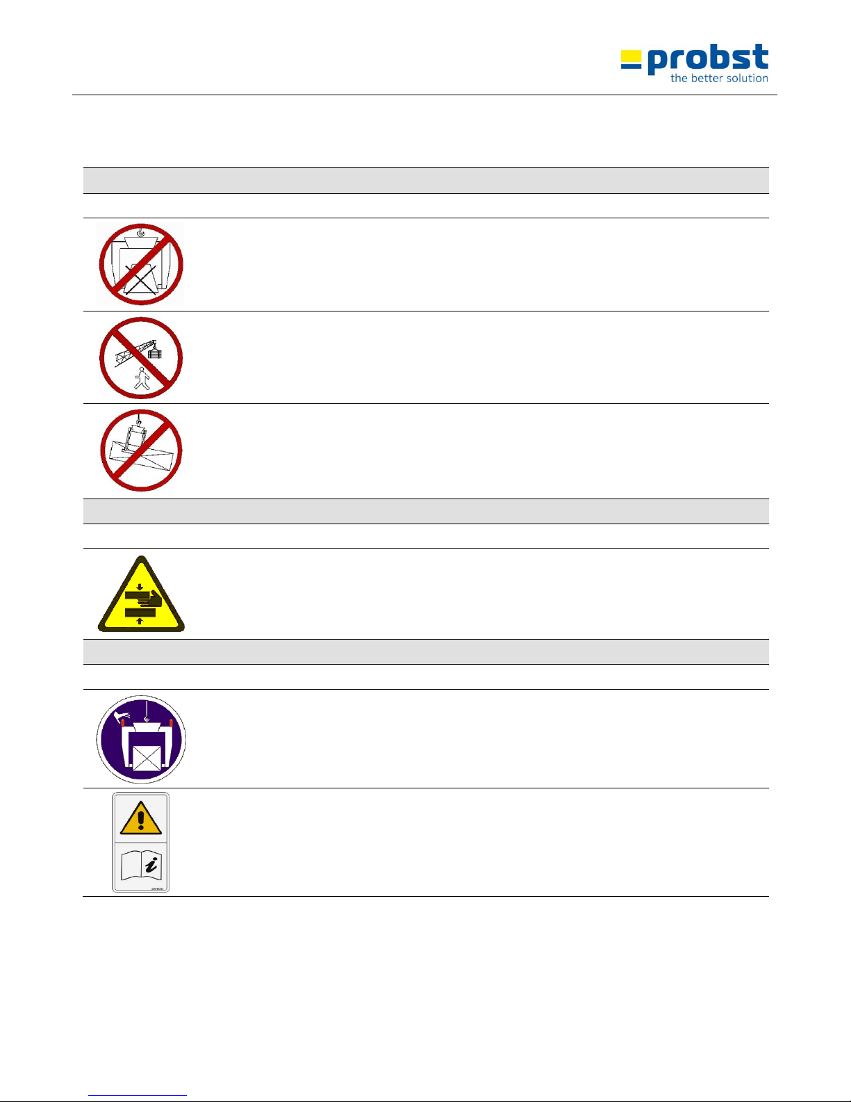
3.4 Safety Marking
PROHIBITION SIGN
Symbol
Meaning
Order-No.:
Size:
The transportation of non rectangular goods is not allowed!
2904.0213
2904.0212
2904.0211
30 mm
50 mm
80 mm
It is not allowed to be under hanging loads. Danger to life!
2904.0210
2904.0209
2904.0204
30 mm
50 mm
80 mm
Do not lift any components off-centre.
2904.0216
2904.0215
2904.0214
30 mm
50 mm
80 mm
WARNING SIGN
Symbol
Meaning
Order-No.:
Size:
Danger of squeezing the hands.
2904.0221
2904.0220
2904.0107
30 mm
50 mm
80 mm
REGULATORY SIGN
Symbol
Meaning
Order-No.:
Size:
Manual guiding is only allowed for machines with handles.
2904.0227
2904.0226
2904.0225
30 mm
50 mm
80 mm
Read operating instructions before operating.
2904.0366
2904.0365
30x57 mm
50x95 mm
Page 7

Operating Instructions
TSZ-UNI
Safety
7 / 22
V4
GB
3.5 Personal safety requirements
● Each operator must have read and understood the operating instructions.
● Only qualified, authorized personal is allowed to operate the device and all devices which are connected
(lifting equipment).
● The manual guiding is only allowed for machines with handles.
3.1 Protective equipment
The protective equipment must consist, according to the safety regulations of
the following parts:
● Protective clothing
● Safety gloves
● Safety shoes
3.2 Accident prevention
● The workplace has to be covered for unauthorized persons, especially children.
● Take care in case of thunderstorm!
● The workplace has to be sufficiently illuminated.
● Take care with handling wet, dirty and not solidified components.
● The working with the device in case of atmospheric editions under 3° C (37,5° F) is forbidden!
Because the goods could be fall down caused by dampness or freezing.
3.3 Function Control
3.3.1 General
● Before using the device check the functions and the working condition.
● Maintenance and lubrication are only permitted when device is shut down!
● Do not use the device, until all faults which can cause safety hazards are removed.
● If there are any cracks, splits or damaged parts on any parts of the device, immediately stop using it.
● The operating instructions must be available at the workplace every time.
● Do not remove the data-plates of the machine.
● Unrecognisable information signs must be replaced.
Page 8
Operating Instructions
TSZ-UNI
Safety
8 / 22
V4
GB
3.4 Safety procedures
3.4.1 General
● The use of the device is only permitted in proximity to the ground. Do not swing it over peoples heads.
● The manual guiding of is only allowed for devices with handles.
● The operator is not allowed to leave the control unit as long as the device loaded with load. The load must
always be in the range of vision of the operator.
● While using the device is the stay of persons in the working area forbidden. Except it is indispensable. Caused
of the way of using the device, e.g. if the device must be leaded by hand.
● The jerky lifting and lowering of the device with and without load. e.g. caused through driving fast with the
support frame/lifting device over uneven grounds is forbidden. Because the gripping good could fall down.
Unchecked movements of the device.
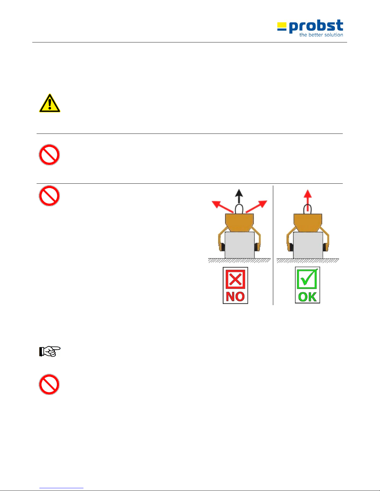
● While using the device be sure that there are no
persons in the working area. Danger to Life!
● Do not pull out stuck or tightened loads with the
device.
● Do not lift any components off-centre, because
that could fall down.
● The device should not be opened if the opening
path of the gripping arm is blocked by a resistance
(e.g. other concrete blocks or the like)!
● Never exceed the carrying capacity and the
nominal width of the device.
● Never pull or drag loads sideways. Otherwise parts
of the device could be damaged.
(see Fig. A )
Fig. A
3.5 Hydraulic excavator and other lifting equipments
● Hydraulic excavator and other lifting equipments have to be in good, safe working condition.
● Only authorized and qualified personnel is allowed to operate the excavator and other lifting equipments.
● The operator staff must have all the necessary qualifications.
● Never exceed the maximum capacity of the hydraulic excavator and other lifting equipments.
Page 9
Operating Instructions
TSZ-UNI
General
9 / 22
V4
GB
4 General
4.1 Authorized use
The device (TSZ-uni) is specially designed for gripping, transporting and the following laying of gripping goods
such as, steps, kerb stones, contact angle, L-stones, as well ashlar rocks (via the assembly of the accessories
“steelfinger grippers WB-SQ”) in conjunction with a corresponding lifting device (e.g. excavator).
This device is series-produced equipped with the following elements:
suspension lug for the crane hook (lifting equipment operation)
handles for the guidance of the device
automatic release for the fully automatic switch over from „full“ to “empty” .
exchangeable rubber bars (as gripping elements)
Accessories:
● steelfinger grippers WB-SQ (43101110) for movements of roughly-cut ashlar rocks .
● Height adjustable support (for gripping in batch operation)
● The device is only designed for the use specified in this documentation.
● Every other use is not authorized and is forbidden!
● All relevant safety regulations, corresponding legal regulations, especially regulations of the declaration of
conformity, and additional local health and safety regulations have to be observed.
Prior to every operation the user must ensure that:
● the equipment is suited to the intended operation, the functioning and the working condition of the
equipment is examined, and the loads are suitable to be handled.
Any doubts about instructions should be raised with the manufacturer prior to use.
ATTENTION: The use of this device is only permitted in proximity to the ground.
Page 10

Operating Instructions
TSZ-UNI
General
10 / 22
V4
GB
Only stone elements with parallel and plane surface are allowed to be picked-up and handled.
Because the gripping good could fall down.
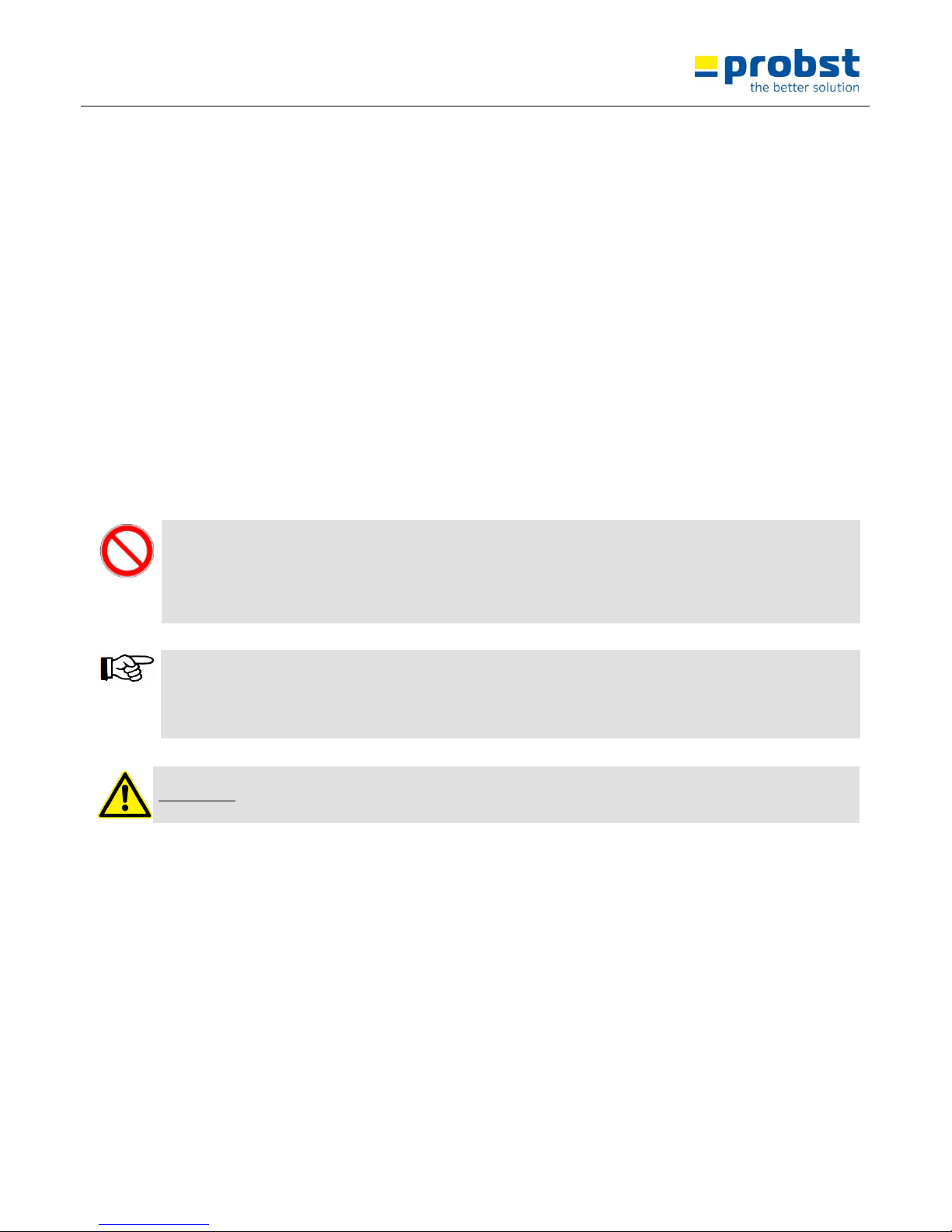
NOT ALLOWED AKTIVITIES:
Unauthorized alterations of the device and the use of any self-made additional equipment
could cause danger and are therefore forbidden!!
Never exceed the carrying capacity and the nominal width/gripping range of the device.
All unauthorized transportations with the device are not allowed:
● Transportation of people and animals.
● Transportation of other loads and materials than described in this
manual.
● Never suspend any goods with ropes, chains or similar at the device.
● Transportation of non rectangular and round gripping goods, because
they could fall down. (see figure to the right).
● Gripping of gripping goods with packaging foil, because they could fall
down.
● Transportation of material with “feet”, “bellies” and “blind spacers”.
Page 11

Operating Instructions
TSZ-UNI
General
11 / 22
V4
GB
4.2 Survey and construction
Fig.1
1
Suspension lug
2
Handles
3
Adjustment of gripping
range
4
Assembly plate for height
adjustable support
(43100867)
5
Spring bolt (for gripping
range adjustment)
6
Rubber gripper bar (PGL3)
7
Automatic release
TSZ-uni (standard)
Fig. 2
TSZ-uni (with accessories A 43100867 )
Fig. 3
A
Height adjustable support
(43100867)
1.1 Technical Data
Type:
Gripping range W
Inside height E
Carrying capacity
Gripper lenght L
Dead weight
TSZ-uni
50 – 600 mm
(2- 23½")
185 mm
(7¼")
600 kg
(1.320 lbs)
350 mm
(13¾")
~ 30 kg
(~ 64 lbs)
Page 12

Operating Instructions
TSZ-UNI
Installation
12 / 22
V4
GB
5 Installation
1.2 Mechanical connection
5.1.1 Suspension lug
● The device is equipped with a suspension lug and can be mounted on various support frames/lifting devices.
● Take careful that the suspension lug is safety joined with the crane hook and can not slip down.
● The maximum carrying capacity of the support frame/lifting device is not allowed to cross over by the
dead weight of the device and the maximum load.
5.1.2 Load hook and chains
● Fit suspension ring in the load hook of the lifting equipment.
● Ensure that the single chains are not twisted and may be easily pulled through the jaws
● Attaching the device to the lifting equipment take care that all local safety regulation is observed.
● It is not allowed to exceed the carrying capacity of the lifting equipment with the device and the maximum
load.
6 Adjustments
6.1 Adjustment - gripping range
Before the product can be lifted and transported, the gripping range has to be adjusted to the dimensions of
the product.
● Caution while adjusting of the gripping range. There is danger of injuring the hands!
● The adjustment of the gripping range may never take place on both sides at the same time.
Always adjust the gripping range first to the one and then on the other side.
● Pull the spring bolt (5) upwards, rotate around 180° and lock in position (in nick).
● Move the rectangular tube (3), until the gripping range is approx. 5 cm larger than the gripping good.
● Pull the spring bolt (5) upwards again and rotate around 180°.
● Move the rectangular tube (3) so long, until the spring bolt engages in one of the holes.
● The adjustment of the gripping range has to follow general symmetrical.
That means, it must be used in each case the same adjustable hole with both rectangular tubes (3).
Page 13

Operating Instructions
TSZ-UNI
Adjustments
13 / 22
V4
GB
● When gripping L-stones, the gripping range must be adjust asymmetrical (because of the center of gravity of
the L-stone, so that when lifting, the L-stone is in horizontal position).
That means, it must NOT be used the same adjustable hole with both rectangular tubes (3) (a asymmetrical
positioning of the adjustable holes up to 2 holes is allowed).
Fig. 1
3
Adjustment positions at the adjustable
hole in both rectangular tubes
4
Height adjustable support
5
Spring bolt
6.1.1 Accessories – height adjustable support
When using the device (TSZ-uni) in batch operation, for gripping of single stone slabs (batched one upon the
other), we advise to use the accessories “height adjustable support” (43100867)! – see Fig. 1
Therefore, the inside height must not always adjusted again for gripping goods with the same dimensions (see
Figure 1). When picking up in batch operation the top stone slab may only be lifted!
● Caution while adjusting of the gripping range. There is danger of injuring the hands!
Page 14

Operating Instructions
TSZ-UNI
Adjustments
14 / 22
V4
GB
● The “height adjustable support (A) is attached to the “mounting plate of the height adjustable support”
see Fig. 2 (and Fig. 3)
● Adjust the “height adjustable support (A) with the adjusting screws and regard the both “height adjustable
supports (A)” have the same height and that the rubber gripper bars are positioned in the middle area of
stone thickness. see Fig. 1
Fig. 1
Fig. 2
Fig. 3
3
Adjustment positions at the adjustable
hole in both rectangular tubes
4
Height adjustable support
5
Spring bolt
Page 15

Operating Instructions
TSZ-UNI
Operation
15 / 22
V4
GB
7 Operation
7.1 Operating for devices with automatic release
● The device is connected to the lifting equipment/support frame (e.g. excavator).
● Before lifting the device, the gripping range has to be adjusted.
● The device is placed over the product, set down, the device closes round the product and it can be lifted.
● Set down on the ground again, the device opens automatically, the automatic release locks it into position so that the
device can be lifted without closing up.
● Placed over the next product, the automatic release disengages itself and the product can be lifted.
● The device therefore is a ONE-MAN-MACHINE.
Shut-down the device without lifting equipment/support frame only on even ground. The gripping arms must
be opened enough, to ensure a secure standing of the device.
Otherwise exists danger of overturning!
7.2 Picture of the automatic release
The device is mounted with a automatic release, that means the opening and closing of the gripping arms results through
the set down and lifting of the device.
Pictures the positions of the automatic release
● Device is lifted through the support
frame.
● Gripping arms are opened.
● Device is set up on the gripping
good.
● Gripping arms are opened.
● Device is lifted through the support
frame.
● Gripping good is clamped and can
be transported to the destination.
/
● Device is set down with the
gripping good (on the ground).
● Gripping arms are opened.
● Device is lifted through the support
frame.
● Gripping arms are opened.
(laydown position of the device on
the ground)
Page 16

Operating Instructions
TSZ-UNI
Operation
16 / 22
V4
GB
7.3 Gripper change (steelfinger grippers TSZ-UNI-WB-SQ)
For movements of roughly-cut ashlar rocks with the device (TSZ-uni) change the standard rubber grippers
(Figure A) againt stellfinger grippers (Figure B)
1.) Unscrew both standard rubber grippers and then
pull them out of the holders (Figure A)
2.) Figure B showws the device (TSZ-uni)
without rubber grippers.
Figure A
Figure B
3.) The steelfinger grippers must be installed as shown in Figure C. Take notice, that "Part 1" (with chain box)
may be mounted only on the left side of the device, thus at the "wide external gripper arm"!
Figure D
Part 1
Part 2
External gripping
arm
Page 17

Operating Instructions
TSZ-UNI
Operation
17 / 22
V4
GB
7.4 Handling with steelfinger grippers (WB-SQ)
Before each use of the device, check the steelfinger grippers for mobility, abrasion and contamination
Worn (no longer sharp-edged) or bent steelfinger grippers must be replaced! Otherwise it exists slipping danger
of the gripping good!
1.) Position the device (TSZ-uni) direct over the gripping
good (ashlar rock).
2.) Put the device (TSZ-uni) at the gripping good (ashlar
rock). Then lift the device (TSZ-uni) approx. 20 cm
(7.8").
3.) Remove the safety chain from the chain box and
throw it under the lifted gripping good (ashlar rock)
see Figure A
4.) Suspend the security chain on the other side of the
device (at the hook ). see Figure B
Never grip with the hands under the gripping good (ashlar rock) – danger of squeezing the hands!
Figure A
Figure B
Page 18
Operating Instructions
TSZ-UNI
Operation
18 / 22
V4
GB
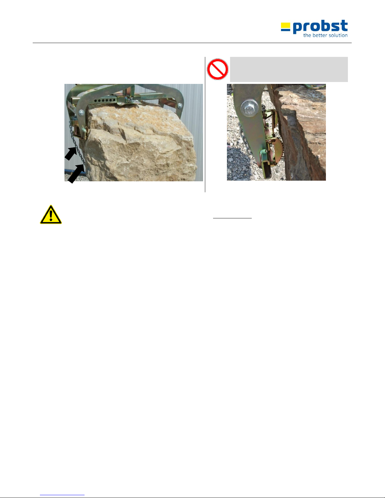
5.) The safety chain must fit tightly (and centric) to the
gripping good (ashlar rock), so that gripping good with
is secured by the security chain! see Figure C
The safety chain must never be used as a
"lifting tackle" to attach the device (TSZ-uni)
on the support frame (e.g. excavators)!
Figure C
Figure D
Before lifting the gripping good (ashlar rock) be sure that the steelfinger grippers do have a good hold/grip and
that the load is distributed evenly, otherwise there is a high risk of accident!
Touch/guide the device (ZSZ-uni) only on the handles and put the feet out of the danger zone.
Page 19

Operating Instructions
TSZ-UNI
Maintenance and care
19 / 22
V4
GB
8 Maintenance and care
8.1 Maintenance
To ensure the correct function, safety and service life of the device the following points must be executed in
the maintenance interval.
Used only original spare parts, otherwise the warranty expires.
All operations may only be made in closed state of the device!
8.2 MECHNICAL
SERVICE INTERVAL
Maintenance work
First inspection after
25 operating hours
● Control and tighten all screws and connections.
(The implementation is only allowed by an expert).
All 50 operating hours
● Tighten all screws and connections (take care that the tightening torques according
to the property class of the screws are observed).
● Check all joints, bolts, guidance’s and gears for correct function, if necessary adjust or
replace it.
● Check all Grippers (if available) for signs of wear.
● Grease all slidings (if available) when the device is in opened position with a spatula.
● Grease all grease nipples (if available) with a grease gun.
Minimum 1x per year
(at rough conditions shorten
the interval)
● Check of all the suspension parts, bolts and straps. Check for corrosion and safety by
an expert.
Rubber gripper bar
Regular control for dirt (e.g. little stone particles) in the upper area (see points in figure detail „X“ in Fig. 2) of
the rubber gripper bar (6) see Fig. 1 / Fig. 2
Problem: Dirt can damage the rubber gripper bar (6) when gripping (when little stone particles are pressed into
the rubber gripper bar).
Redress: Remove the dirt in this area at the rubber gripper bar (6), or when heavy polluted, dismount and clean
the rubber gripper bar.
Fig. 1
Fig. 2
Page 20

Operating Instructions
TSZ-UNI
Maintenance and care
20 / 22
V4
GB
8.2.1 Additional with steelfinger grippers (WB-SQ)
Before each start-up:
● Check all steelfinger grippers for mobility, abrasion and contamination.
Worn (no longer sharp-edged) or bent steelfinger grippers must be replaced!
Regular:
● Cleaning of the device with high pressure cleaner (warm water).
Weekly:
● Lubricate and oil mobile parts
AUTOMATIC-RELEASE
Never grease the automatic-release, if necessary use oil!
8.3 Trouble shooting
ERROR
CAUSE
REPAIR
The clamping-power is not big enough,
the load is slipping out
(optional)
The grippers are worn
Replace the grippers
(optional)
The maximum load is exceed
Reduce the weight of. the load
(Adjustment of the gripping range)
(optional)
The actual opening width is not
correct
Adjust the gripping range
according to the load you want to
transport
(Property of material)
The surface of the material is dirty
or the material is not suitable /
allowed for this device.
Check the surface of the material
or ask the manufacturer, if you the
material is allowed for this device.
Unbalanced load
The device is not loaded
symmetrically
Adjust the position of the load
(Adjustment of the gripping range)
(optional)
The adjustment of the gripping
range is not symmetrical.
Correct the adjustment of the
gripping range
Automatic release does not work
mechanical (optional)
Automatic release does not work
Clean automatic release with high
pressure-cleaner
Oil the automatic release (never
with grease)
Change the inset of the automatic
release
Page 21

Operating Instructions
TSZ-UNI
Maintenance and care
21 / 22
V4
GB
8.4 Repairs
● Only persons with the appropriate knowledge and ability are allowed to repair the device.
● Before the device is used again, it has to be checked by an expert.
8.5 Safety procedures
It is the contractors responsibility to ensure that the device is checked by an expert in periods of max. 1
year and all recognized errors are removed ( see BGR 500).
The corresponding legal regulations and the regulations of the declaration of conformity have to be
observed!
We recommend, that after checking the device the badge „Safety checked“ is put on the device.
(Order-No.: 2904.0056+inspection sticker with date).
● You can receive these badges from us.
The check by an expert must be proved!
Device
Year
Date
Expert
Company
Page 22

Operating Instructions
TSZ-UNI
Maintenance and care
22 / 22
V4
GB
8.6 Hints to the identification plate
Type, serial-number and production year are very important for the identification of your device. If you need
information to spare-parts, warranty or other specific details please refer to this information.
The maximum carrying capacity is the maximum load which can be handled with the device. Do not exceed this
carrying capacity.
If you use the device in combination with other lifting equipment (Crane, chain hoist, forklift truck, excavator)
consider the deadweight of the device.
Example:
8.7 Hints to the renting/leasing of PROBST devices
With every renting/leasing of PROBST devices the original operating instructions must be included
unconditionally (in deviation of the users country's language, the respective translations of the original operating
instructions must be delivered additionally)!
Page 23

W min. 50
69
(im WA hängend)
W max. 600
(
186
)
Et ca. 185
ca.
177
ca.
598
(im WA hängend)
550
Bkl
350
Tragfähigkeit / load capacity: 600 kg
A
B
C
D
E
F
8
7
6
5
4
3
2
1
4
5
6
7
8
F
E
D
C
B
1
31,5 kg
Schutzvermerk nach DIN 34 beachten!
Nachdruck nur mit unserer Genehmigung!
Gewicht:
Bei Änderungungen Rücksprache TB !
Kunde:
WA:
1
Joerg.Werner
3.6.2014
Klaus.Scholl
18.10.2004
Gepr.
Erst.
Name
Datum
von
Blatt
Ers. d.
Ers. f.
53100251
Urspr.
Zust.
1
D53100338
Artikelnummer/Zeichnungsnummer
Trittstufenversetzzange TSZ-uni m. WA
Benennung
Page 24

20000026
20440006
33100003
20100084
20030011
33100003
20440006
20000026
20540033
43100861
21600002
20100016
43100282
20540033
43100859
21600002
43100858
43100860
20100084
33100003
20440006
20030011
20000026
20030011
20000026
20440006
33100003
20100084
20030011
43100856
36370019
36370019
A
B
C
D
E
F
8
7
6
5
4
3
2
1
4
5
6
7
8
F
E
D
C
B
1
31,5 kg
Schutzvermerk nach DIN 34 beachten!
Nachdruck nur mit unserer Genehmigung!
Gewicht:
Bei Änderungen Rücksprache TB !
Kunde:
WA:
1
Joerg.Werner
3.6.2014
Klaus.Scholl
18.10.2004
Gepr.
Erst.
Name
Datum
von
Blatt
Ers. d.
Ers. f.
53100251
Urspr.
Zust.
1
E53100338
Artikelnummer/Zeichnungsnummer
Trittstufenversetzzange TSZ-uni m. WA
Benennung
Page 25

Proof of maintenance
Warranty claim for this machine only apply for performance of the mandatory maintenance works (by an
authorised specialist workshop)! After each completed performance of a maintenance interval the
included form must be fill out, stamped, signed and send back to us immediately
1)
.
1) via e-mail to service@probst.eu / via fax or post
Operator: _ _ _ _ _ _ _ _ _ _ _ _ _ _ _ _ _
Device type: _ _ _ _ _ _ _ _ _ _ _ _ _ _ _ _
Article -No.: _ _ _ _ _ _ _ _ _ _ _ _ _ _ _
Device-No.: _ _ _ _ _ _ _ _ _ _ _ _
Year of make: _ _ _ _
First inspection after 25 operating hours
Date:
Maintenance work:
Inspection by company:
Company stamp
………………………………………………………………
Name Signature
All 50 operating hours
Date:
Maintenance work:
Inspection by company:
Company stamp
………………………………………………………………
Name Signature
Company stamp
………………………………………………………………
Name Signature
Company stamp
………………………………………………………………
Name Signature
Minimum 1x per year
Date:
Maintenance work:
Inspection by company:
Company stamp
………………………………………………………………
Name Signature
Company stamp
………………………………………………………………
Name Signature
Page 26

Proof of maintenance
Warranty claim for this machine only apply for performance of the mandatory maintenance works (by an
authorised specialist workshop)! After each completed performance of a maintenance interval the
included form must be fill out, stamped, signed and send back to us immediately
1)
.
1) via e-mail to service@probst.eu / via fax or post
Operator: _ _ _ _ _ _ _ _ _ _ _ _ _ _ _ _ _
Device type: _ _ _ _ _ _ _ _ _ _ _ _ _ _ _ _
Article -No.: _ _ _ _ _ _ _ _ _ _ _ _ _ _ _
Device-No.: _ _ _ _ _ _ _ _ _ _ _ _
Year of make: _ _ _ _
First inspection after 25 operating hours
Date:
Maintenance work:
Inspection by company:
Company stamp
………………………………………………………………
Name Signature
All 50 operating hours
Date:
Maintenance work:
Inspection by company:
Company stamp
………………………………………………………………
Name Signature
Company stamp
………………………………………………………………
Name Signature
Company stamp
………………………………………………………………
Name Signature
Minimum 1x per year
Date:
Maintenance work:
Inspection by company:
Company stamp
………………………………………………………………
Name Signature
Company stamp
………………………………………………………………
Name Signature
Page 27

Proof of maintenance
Warranty claim for this machine only apply for performance of the mandatory maintenance works (by an
authorised specialist workshop)! After each completed performance of a maintenance interval the
included form must be fill out, stamped, signed and send back to us immediately
1)
.
1) via e-mail to service@probst.eu / via fax or post
Operator: _ _ _ _ _ _ _ _ _ _ _ _ _ _ _ _ _
Device type: _ _ _ _ _ _ _ _ _ _ _ _ _ _ _ _
Article -No.: _ _ _ _ _ _ _ _ _ _ _ _ _ _ _
Device-No.: _ _ _ _ _ _ _ _ _ _ _ _
Year of make: _ _ _ _
First inspection after 25 operating hours
Date:
Maintenance work:
Inspection by company:
Company stamp
………………………………………………………………
Name Signature
All 50 operating hours
Date:
Maintenance work:
Inspection by company:
Company stamp
………………………………………………………………
Name Signature
Company stamp
………………………………………………………………
Name Signature
Company stamp
………………………………………………………………
Name Signature
Minimum 1x per year
Date:
Maintenance work:
Inspection by company:
Company stamp
………………………………………………………………
Name Signature
Company stamp
………………………………………………………………
Name Signature
 Loading...