

Page 1

SPEEDY VS-140 Vacuum Hand Laying Device
VS-140-110
2
Order-No:
5270.0008
Serial-No.:
SPEEDY VS-140 Vacuum Hand Laying Device
VS-140-110
V2
Translation of original operating instructions
Page 2

Contents
VS-140-110
V2
06/08/14
2 / 24
1 Contents
1 Contents ............................................................................................................................... 2
2 EC-Declaration of conformity............................................................................................... 4
3 Safety .................................................................................................................................... 6
3.1 Instructions for the Owner .............................................................................................. 6
3.2 Instructions for the Installation, Maintenance and Operating Personnel ....................... 6
3.3 Hazard Alert Symbols ...................................................................................................... 6
3.4 Installation Site Requirements ........................................................................................ 6
3.5 Intended Use ................................................................................................................... 7
3.6 Emissions ......................................................................................................................... 7
3.7 Special Hazards ................................................................................................................ 7
3.8 Workplaces ...................................................................................................................... 7
3.9 Instructions for the Operator .......................................................................................... 7
3.10 Equipment for Personal Protection ............................................................................. 7
3.11 Behaviour in Emergencies ............................................................................................ 7
3.12 Checking the Safety Devices ........................................................................................ 8
3.12.1 Checking the Vacuum Gauge .................................................................................... 8
3.12.2 Cleaning the air filter................................................................................................. 8
3.13 Safety Marking ............................................................................................................. 9
4 Technical Data ..................................................................................................................... 10
4.1 Dimensioned Drawing.....................................................................................................10
4.2 Technical Data ................................................................................................................. 11
5 Description .......................................................................................................................... 12
5.1 Components of the Lifting Device .................................................................................. 12
5.2 Controls ........................................................................................................................... 12
5.2.1 Push switch .............................................................................................................. 12
5.2.2 Operating lever ........................................................................................................ 12
5.3 Vacuum generator .......................................................................................................... 12
5.4 Suction pads.................................................................................................................... 12
Page 3

Contents
VS-140-110
V2
06/08/14
3 / 24
6 Installation ........................................................................................................................... 14
6.1 Preparing for use ............................................................................................................ 14
6.2 Switching off at the end of the day ................................................................................ 15
7 Operating............................................................................................................................. 16
7.1 Safety Instructions ..........................................................................................................16
7.2 Lifting, Transporting and Lowering Loads ...................................................................... 17
7.2.1 Lifting Loads ............................................................................................................ 17
7.2.2 Transporting Loads .................................................................................................. 17
7.2.3 Lowering Loads ....................................................................................................... 17
7.3 Handle height adjustment .............................................................................................. 17
8 Troubleshooting .................................................................................................................. 18
9 Maintenance ........................................................................................................................ 19
9.1 General ............................................................................................................................19
9.2 Maintenance Plan ...........................................................................................................19
9.3 Suction Pads / Seals........................................................................................................ 20
9.4 Leak Test ........................................................................................................................ 20
9.5 Safety procedures ........................................................................................................... 21
9.6 Hints to the identification plate ..................................................................................... 22
9.1 Hints to the renting/leasing of PROBST devices ............................................................ 22
10 Spare Parts ......................................................................................................................... 23
Page 4

EC-Declaration of conformity
VS-140-110
V2
06/08/14
4 / 24
2 EC-Declaration of conformity
DESCRIPTION:
SPEEDY VS-140 Vacuum Hand Laying Device
VS-140-110
Manufacturer:
Probst GreiftechnikVerlegesysteme GmbH
Gottlieb-Daimler-Strasse 6
D-71729 Erdmannhausen
info@probst.eu www.probst.eu
Complies with the following provisions applying to it
EC-machinery directive 2006/42/EG
DIN EN ISO 12100
Safety of machinery - General principles for design - Risk assessment and risk reduction (ISO 12100:2010)
DIN EN ISO 13857
Safety of machinery ― Safety distances to prevent hazard zones being reached by upper and lower limbs (ISO
13857:2008)
DIN EN 349 (ISO 13854)
Minimum distance to avoid squeezing any parts of the body
Page 5

EC-Declaration of conformity
VS-140-110
V2
06/08/14
5 / 24
DIN 45635-13
Measurement of airborne noise emitted by machines (displacement-, turbo- and jet-compressors).
DIN EN 1012-1 / DIN EN 1012-2
Compressors and vacuum pumps; Safety requirements part 1 and 2.
DIN EN 60204-1 (IEC 60204-1)
Safety of machinery, electrical equipment of industrial machines. Part 1: General requirements
2006/95/EG (Low voltage standard)
2004/108/EG (Electromagnetic compatibility)
DIN EN 55014-1 (IEC/CISPR 14-1)
Electromagnetic compatibility – Requirements for household appliances, electric tools, and similar apparatus.
Part 1: Emission.
DIN EN 55014-2 (IEC/CISPR 14-2)
Electromagnetic compatibility – Requirements for household appliances, electric tools, and similar apparatus.
Part 2: Immunity.
Authorized person for EC-dokumentation:
Name: J. Holderied
Address: Probst GreiftechnikVerlegesysteme GmbH; Gottlieb-Daimler-Str. 6; D-71729 Erdmannhausen
Signature, informations to the subscriber:
Erdmannhausen, 06.08.2014..........................................................................
(M. Probst, Managing director)
Page 6

Safety
VS-140-110
V2
06/08/14
6 / 24
3 Safety
3.1 Instructions for the
Owner
The lifting devices SPEEDY VS-S series are manufactured according to current technical
standards and are safe. Nevertheless, they will present hazards
● if they are not operated by qualified or at least trained staff,
● if they are used contrary to the approved applications.
This may result in
● injuries to or death of operators and other persons,
● damage to lifting device and other valuable goods.
3.2 Instructions for the
Installation,
Maintenance and
Operating Personnel
The device must be installed and maintained by qualified personnel, mechanics and
electricians.
Each person in your company involved in the installation, commissioning, operation,
maintenance or repair of the device
● must have read and understood these operating instructions
● and especially the chapter "Safety" herein.
Your company must ensure by internal measures
● that the operators of the lifting device are properly trained,
● that they have read and understood the operating instructions,
● that the operating instructions are available to them at all times.
The responsibilities for the tasks carried out with the device must be clearly defined
and observed. Ambiguity regarding responsibilities must not exist.
3.3 Hazard Alert Symbols
Danger
Attention
Prohibition
Die Sicherheitshinweise sind in dieser Anleitung sind wie folgt gekennzeichnet:
Danger to life!
Identifies imminent hazard. If you do not avoid the hazard, death or severe injury will
result.
Hazardous situation!
Identifies a potentially hazardous situation. If you do not avoid the situation, injury or
damage to property can result.
Prohibition!
Identifies imminent a prohibition. If you do not avoid the prohibition, death and severe
injury, or damage to property will result.
3.4 Installation Site
Requirements
The lifting device may not be operated in rooms which contain explosive atmospheres.
The ambient temperature of 40 °C must not be exceeded.
Ensure by internal instructions and checks that the installation site is always kept clean
and tidy.
Page 7

Safety
VS-140-110
V2
06/08/14
7 / 24
3.5 Intended Use
Prohibition
Lifting devices of the SPEEDY VS-S are designed for lifting and moving stone and
concrete slabs. Operation requires two persons.
The maximum lifting capacity must not be exceeded.
The lifting device may be used only in vertical position.
Transport of persons and animals with the load or the lifting device itself is forbidden!
Unauthorised modification of the lifting device is forbidden for safety reasons!
The operating, maintenance and service instructions in this manual must be
observed.
3.6 Emissions
The equivalent continuous sound pressure level of the device is
approx. 80 dB(A).
3.7 Special Hazards
Danger
Since the load is held by a vacuum, it will fall off as soon as this vacuum is lost.
This can happen if the vacuum generator fails.
If the vacuum generator fails, lower the load immediately if this is possible.
If this is not possible, immediately leave the dangerous area near the load.
The device generates a very strong suction which can draw in hair and clothing. Do not
look into the suction opening when the device is switched on. Parts of body can be
sucked in.
3.8 Workplaces
The device is operated always by two persons. The workplace of the operators is in
front of the control handles.
Stand so that you can constantly observe the vacuum gauge.
3.9 Instructions for the
Operator
As an operator of the lifting device, you must be trained before you start to use the
device. You must have read and understood the operating instructions and especially
the chapter "Safety".
Ensure that only authorised persons use the device. You are responsible for others in
the operating range of the equipment.
Local safety requirements are fully applicable. The safety instructions in this document
complement these local regulations and do not supersede them.
3.10 Equipment for
Personal Protection
When operating the device always wear:
● safety shoes (with steel toecaps),
● tough gloves.
3.11 Behaviour in
Emergencies
Danger
An emergency situation exists when
● power suddenly fails (device switches off),
● the vacuum pressure drops in the red danger zone on the scale of the vacuum
gauge.
Lower the load immediately if possible. If this is not possible, immediately leave the
dangerous area near the load, since it will be dropped from the device.
Page 8

Safety
VS-140-110
V2
06/08/14
8 / 24
3.12 Checking the Safety
Devices
The lifting device is equipped with following safety device:
vacuum gauge with red danger zone
Check this device at the beginning of each shift (when operating in shifts) or once a
week (when operating continually).
3.12.1 Checking the
Vacuum Gauge
Switch on the lifting device.
Place the lifting device on a flat floor and apply vacuum.
When the vacuum has built up, the pointer of the vacuum gauge must reach a vacuum
of at least -0,2 bar.
3.12.2 Cleaning the air
filter
Inspect the air filter at least once per week and clean it (by blowing out the dirt) as
necessary.
Attention
If the air filter is dirty, the manometer will show a higher value than is actually available
at the suction plates.
The air filter must therefore be inspected and cleaned regularly in order to maintain
the operational safety of the device.
Correct any faults before using the device.
If faults occur during operation, switch the device off and correct the faults before
continuing work with the
device.
Page 9
Safety
VS-140-110
V2
06/08/14
9 / 24
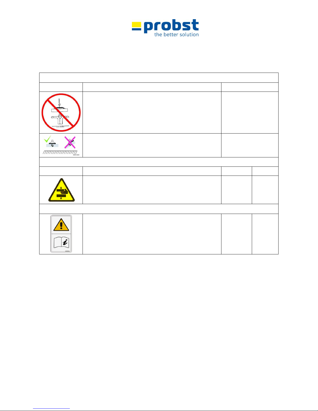
3.13 Safety Marking
WARNING SIGN
Symbol
Meaning
Order-No.:
It is not allowed to be under hanging loads. Danger to life!
2904.0101
Do not lift any components off-centre.
2904.0058
WARNING SIGN
Symbol
Meaning
Order-No.:
Size:
Danger of squeezing the hands.
2904.0221
2904.0220
2904.0107
30 mm
50 mm
80 mm
REGULATORY SIGN
Read operating instructions before operating.
2904.0366
2904.0365
30x57 mm
50x95 mm
Page 10

Technical Data
VS-140-110
V2
06/08/14
10 / 24
4 Technical Data
4.1 Dimensioned Drawing
Pos
Description
Pos
Description
1
Operator handles
6 Cover of the device
2
Upper part of the device with blower motor
7 Operating lever
3
Suction plate
8 Push switch
4
Ventilating flap
9 Vacuum gauge
5
Lower part of the device
1
2
3 4 5
6 7 8
9
Page 11

Technical Data
VS-140-110
V2
06/08/14
11 / 24
4.2 Technical Data
Blower motor, Power
1500 W
Blower motor, Voltage / Frequency
110 V 50 / 60 Hz
Temperature range
0°C ... 40 °C
Lifting load (at -200 mbar low pressure)
depending on size of suction plate
Dead weight*
~14 kg ( ~ 31 lbs)
Dimension of the suction plate
390 x 290 mm
Standard Suction Plates SPS for VS-S
Type
Length mm (in)
Width mm (in)
Carrying Capacity kg (lbs)
Order-Nr.
SPS 40 VS
300 (11 ¾")
250 (9 ¾")
40 * (90) *
4271.0013
SPS 75 VS
400 (15 ¾")
300 (11 ¾")
75 * (165) *
4271.0008
SPS 90 VS
500 (19 ¾")
300 (11 ¾")
90 * (200) *
4271.0012
SPS 120 VS
700 (27 ½")
300 (11 ¾")
120 * (265) *
4271.0011
Replacement seal:
(easy to attach without glueing)
Order-Nr.
for SPS 50 VS-140 **
4271.0023
for SPS 80 VS-140 **
4271.0029
for SPS 100 VS-140 **
4271.0031
for SPS 140 VS-140 **
4271.0030
* Value at -200 mbar low pressure
** inkl. Spannband
Page 12

Description
VS-140-110
V2
06/08/14
12 / 24
5 Description
5.1 Components of the Lifting Device
Parts with safety functions appear in bold type
Pos
Description
Pos
Description
1
Operator handles
6 Cover of the device
2
Upper part of the device with blower motor
7 Operating lever
3
Suction pad
8 Push switch
4
Ventilating flap
9 Vacuum gauge
5
Lower part of the device
5.2 Controls
5.2.1 Push switch
The push switch is used for switching the unit on and off.
5.2.2 Operating lever
Attention
The operating lever is used for releasing the load by opening the venting valve.
This lever may be actuated only when the load is resting on a solid surface.
When the lever is actuated, the vacuum is released immediately and the unit can be
lifted off the workpiece.
5.3 Vacuum generator
The vacuum is generated by an electrically driven blower.
5.4 Suction pads
Danger
The suction pads are designed to lift various items. Only items with smooth, air-tight
surfaces are suitable for vacuum lifting.
To generate vacuum, the suction pad must be in contact with and attached to the
load.
The suction pad must always be positioned in the centre of the workpiece in order to
ensure even distribution of the load. If the suction pad is positioned off-centre, the
workpiece may suddenly drop from the unit during lifting and lowering operations,
since the load is then one-sided.
Only suction plates of the manufacturer PROBST shall be used!
Page 13

Description
VS-140-110
V2
06/08/14
13 / 24
● The device is only designed for the use specified in this documentation.
● Every other use is not authorized and is forbidden!
● All relevant safety regulations, corresponding legal regulations, especially regulations of the declaration of
conformity, and additional local health and safety regulations have to be observed.
Prior to every operation the user must ensure that:
● the equipment is suited to the intended operation, the functioning and the working condition of the
equipment is examined, and the loads are suitable to be handled.
Any doubts about instructions should be raised with the manufacturer prior to use.
ATTENTION: The use of this device is only permitted in proximity to the ground.
Some suction plates which can be mounted to the device will reduce its carrying capacity.
The maximum load is indicated on each suction plate.
Use only suction plates which are approved for this device!
Do not exceed the maximum carrying capacity of the suction plates!!!
Danger: Load (stone slabs) will fall down!
● The load (stone slabs) which is to be sucked and
transported, must have sufficient inherent stability,
otherwise there is risk of breakage when lifting!
● Stone slabs must not be bend when lifting - especially
take care with thin and large-sized stone slabs!
● Generally, the load (stones slab) is only to be sucked in
the middle, otherwise the load hangs diagonally under
the device and the load could break - especially when
lifting large stone slabs with a small suction plate.
● Standard suction plates are not suitable for the
transport of glass plates!
NOT ALLOWED AKTIVITIES:
Unauthorized alterations of the device and the use of any self-made additional equipment
could cause danger and are therefore forbidden!!
Never exceed the carrying capacity and the nominal width/nominal size of the device.
All unauthorized transportations with the device are not allowed:
● Transportation of people and animals.
● Transportation of other loads and materials than described in this manual.
● Never suspend any goods with ropes, chains or similar at the device.
Page 14

Installation
VS-140-110
V2
06/08/14
14 / 24
6 Installation
6.1 Preparing for use
Attention
Move the operator handles (1) to the working position as follows: remove the spring
clips (2) from the pins, pull out the pins, move the handles to the desired position (Pos.
1), insert the pins and secure them with the spring clips.
Danger
Connect electric power to the lifting device. Before connecting, check that the local
voltage and frequency agree with the values shown on the rating plate. If this is not
the case, do not connect the power.
The locally provided power cable (3) must be capable of carrying the rated current of
the lifting device.
Secure the cable (3) to the operator handle (1) with the aid of the Velcro strip (4)
provided for this purpose, to secure the plug-and-socket connection against accidental
releasing (e.g. step on the cable: losing of the load).
Transport position
Working position
Page 15

Installation
VS-140-110
V2
06/08/14
15 / 24
6.2 Switching off at the
end of the day
Before switching off the device with the push switch, allow it to run for at least 30
seconds with the venting valve open
This loosens and removes any dirt which may have been deposited on the vacuum
blower.
For transport, swing the operator handles (1) down as follows:
remove the spring clips (2) from the pins, pull out the pins, move the handles to the
transport position (Pos. 2), insert the pins and secure them with the spring clips.
This lifts the suction pad from the ground, protecting it from damage during transport.
Transport position
Page 16

Operating
VS-140-110
V2
06/08/14
16 / 24
7 Operating
7.1 Safety Instructions
● The ground or floor in the working area should by clean and dry or rough enough
to ensure that the operating personnel cannot slip.
● The device is intended only for manual transport of paving stones or slabs. Never
suspend it from a crane or mechanical shovel, etc.
Local safety requirements are fully applicable. The following safety instructions
supplement the local regulations and do not supersede them:
● Wear safety shoes, gloves and ear protection.
● Never exceed the maximum lifting capacity of the device.
● Do not stand below the load. Always keep clear of the load.
● Never carry people or animals with the load or the lifting device itself!
● Operate only when you can view the entire working area. Look out for other
persons in the working area. Never manoeuvre loads above people.
● Do not release the handles while a load is attached.
● Do not pull loads to the side or drag them along with the lifting device.
● If the load has become jammed, do not attempt to tear it free with the lifting
device.
● In the case of a fault in the vacuum generator, lower the load immediately if
possible. Immediately leave the danger area near the load.
● Pick up and lift only appropriate loads (check for stability and porosity).
● Always keep an eye on the vacuum gauge. Never lift loads when the vacuum is
below –200 mbar. If the pointer of the pressure gauge moves into the red danger
zone, lower the load immediately.
● Place workpieces only on clear, level surfaces, since they may otherwise slide
away when released.
● Release the load only when it has been fully lowered to the ground. Do not reach
under the load when lowering it, since serious injuries may result!
● Always distribute load evenly on the suction surfaces.
● Ensure that the vacuum generator cannot be switched off while transporting
loads.
● Check all suction hoses and clamps for proper installation and tighten the clamps
if necessary.
● If you set down the unit with the motor running, take care not to place it on an
airtight surface, since this will block the flow of cooling air. Instead, place the unit
on a support (such as a block of wood).
● Always switch off the unit if you do not intend to use it again within two minutes
Page 17

Operating
VS-140-110
V2
06/08/14
17 / 24
7.2 Lifting, Transporting
and Lowering Loads
The following operating steps must be checked by a qualified mechanic prior to use of
the device by the operating personnel. Correct any faults before the device is used.
7.2.1 Lifting Loads
● Switch the blower on.
● Position the lifting device directly above the load. Do not pull to the sides.
Distribute load evenly.
● Lower the lifting device onto the load.
● The suction pad grips the load.
● Watch the pressure gauge. As soon as a vacuum pressure of -200 mbar has been
reached (pointer of the vacuum gauge is in the green range) you can lift the load.
Never attempt to lift the load with a lower vacuum since it will be dropped.
● When lifting items from a stack, ensure that only one piece is actually lifted.
● The duty cycle (lifting/venting) should not exeed 2/3 to 1/3.
● Maximum lifting period 30 seconds, followed by 15 seconds with inlet free.
7.2.2 Transporting Loads
Avoid jerky movement of the load.
The operator who actuates the operating lever must always inform the second
operator clearly and unambiguously of his intended actions.
7.2.3 Lowering Loads
Lower the load to a safe and clear, level surface so the load cannot slip or tip over.
Pull the operating lever to release the load.
7.3 Handle height
adjustment
The operator handles can be adjusted for operators of differing heights. This may be
done only when the device is resting on the ground.
Remove the spring clips, move the pins to the desired position and secure the pins
again with the spring clips.
Page 18

Troubleshooting
VS-140-110
V2
06/08/14
18 / 24
8 Troubleshooting
The device may be installed and maintained only by qualified personnel such as
mechanics and electricians.
After any repair or maintenance work, check the safety devices as described in the
section “Safety”.
Fault
Cause
Remedy
Vacuum generation does not
work
no current supply
check the current supply
if the thermal protection switch
trips, allow the unit to cool
When the temperature has dropped to
normal (after about 30 minutes) the unit
is ready for use again.
The unit must not be opened during the
guarantee period as this will entail loss of
guarantee cover.
In order to avoid tripping of the thermal
protection switch, follow the instructions
in the section "Safety Notes".
Vacuum does not reach
-200 mbar
Workpiece has cracks, openings
or is porous
Work piece not suitable for this device
Seal damaged
Replace seal
Vacuum gauge defective
Replace vacuum gauge
Air filter dirty
Clean the air filter
Page 19

Maintenance
VS-140-110
V2
06/08/14
19 / 24
9 Maintenance
9.1 General
The device may be installed and maintained only by qualified personnel such as
mechanics and electricians.
Always disconnect the electric power before starting any maintenance work.
The fans must not be opened during the guarantee period as this will entail loss of
guarantee cover.
After any repair or maintenance work, check the safety devices as described in the
section "Safety".
9.2 Maintenance Plan
Interval
Daily
Weekly
Monthly
Every 6
months
Every 12
months
Inspect the safety devices:
- Vacuum gauge OK?
X X
Electrical equipment OK? Cable glands tight?
X
Vacuum hoses in good condition (no cracks, not kinked, no
abrasion, free of leaks)?
X X
All connections (hose clamps, etc.) tight?
X
Instruction plate, rating plate and load plate still mounted on
the device?
X
Operating instructions available?
Operating personnel familiar with operating instructions?
X
Inspect load-carrying part (such as suspension) for
deformation, wear and other damage.
x
Clean and inspect suction pads. Must be free of cracks, lip
must be smooth, etc. Replace if necessary.
X X
Clean the air filter
X
Is the inspection sticker up to date?
X
General condition of the device.
X
Leak test
X X
Page 20

Maintenance
VS-140-110
V2
06/08/14
20 / 24
9.3 Suction Pads / Seals
Remove any foreign bodies and contamination such as adhesives, glue, sawdust, dust,
etc. sticking to the seals at least once a week. Use glycerine to clean the seals.
Immediately replace damaged seals (tears, holes, waves).
Do not use petrol (gasoline).
Use cleaning agent to clean the device (do not use petrol (gasoline) or aggressive or
corrosive fluids to clean the device. The hoses will otherwise become leaky or be
destroyed).
Suction plates must always be replaced completely. The bolts of the suction plate can be
loosened more easily by heating.
9.4 Leak Test
Check the device for leaks at least every three months.
● Apply the suction pad to a flat air-tight surface.
● Switch the vacuum blower on and wait until a vacuum of at least -200 mbar
is reached.
If this vacuum level is not reached, check:
● whether the seals or hoses are damaged,
● that the connectors are tight,
● that the filter element is clean.
Page 21

Maintenance
VS-140-110
V2
06/08/14
21 / 24
9.5 Safety procedures
● It is the contractors responsibility to ensure that the
device is checked by an expert in periods of max. 1
year and all recognized errors are removed ( BGR
500).
● The corresponding regulations of the declaration of
conformity have to be observed!
● We recommend, that after checking the
device the badge „Safety checked“ is put
on the device.
(Order-No.: 2904.0056 + inspection
sticker with date)You can receive these
badges from us.
The check by an expert must be proved!
Device
Year
Date
Expert
Company
Page 22

Maintenance
VS-140-110
V2
06/08/14
22 / 24
9.6 Hints to the identification plate
Type, serial-number and production year are very important for the identification of your device. If you need
information to spare-parts, warranty or other specific details please refer to these information.
The max. carrying capacity is the maximum load which can be handled with the device. Do not exceed this
carrying capacity.
If you use the device in combination with other lifting equipment (Crane, chain hoist, forklift truck,
excavator) consider the deadweight of the device
Example:
9.1 Hints to the renting/leasing of PROBST devices
With every renting/leasing of PROBST devices the original operating instructions must be included
unconditionally (in deviation of the users country's language, the respective translations of the original operating
instructions must be delivered additionally)!
Page 23

Spare Parts
VS-140-110
V2
06/08/14
23 / 24
10 Spare Parts
This equipment is guaranteed in accordance with our General Conditions of Business. This also applies to spare
parts where these are original parts supplied by us. We will assume no liability for damage caused by the use of
non-original spare parts and accessories.
Wear and consumable parts are not covered by the guarantee.
Page 24

Spare Parts
VS-140-110
V2
06/08/14
24 / 24
* When the sealing ring is replaced, a new clamping strip and clamp must always be fitted.
Pos.
Bezeichnung / Description
Art.-No.
1
Betätigungshebel BH 90.800 / operating lever
4271.0036
2
Rundlitze mit Kugelpressnippel / round stranded wire with ball for bowden cable
siehe/see Pos.7
3
Runddrahthülle / cover for bowden wire
siehe/see Pos.7
4
Klett-/Velourband / belt
-----
5
Lamellenstopfen / plug
4271.0055
6
Unterteil / lower part
4271.0056
7
Bowdenzug / Bowden wire
2100.0157
8
Stellschraube / adjusting screw
4271.0057
9
Druckfeder-1.50 / pressure spring
4271.0058
10
Blechschraube / tappino screw
-----
11
V-Dichtring 90 s über Saugplatte / gasket between suction pad and device V-Ring 90 s
4271.0010
12
Federsteckpolzen verzinkt / spring bolt
4271.0052
13
Ein- und Ausschalter / on/off switch
2410.0194
14
Kondensator / condenser
4271.0062
15
Stopfen / plug
4271.0063
16
Manometer VAM 63/1-175H / vacuum gauge
2213.0016
17
Belüftungsklappe / ventilation flap
4271.0064
18
Gebläseeinheit komplett montiert für 230 V / fan unit (complete) for 230 V
4271.0061
19
Dichtung für Gebläse / seal for fan
4271.0059
20
Oberteil / upper part
4271.0060
21
Deckel für Speedy VS2 / cover for VacuMaster Speedy
4271.0065
22
Gebläse für Speedy VS2 230 V / fan for VacuMaster Speedy 230 V
4271.0034
Gebläse für Speedy VS2 110 V / fan for VacuMaster Speedy 110 V
4271.0035
23
Bedienbügel BB / operator handles
4271.0066
-
Sauggreifer komplett / suction pad (complete)
-----
-
Dichtring für Sauggreifer* / sealing lip for suction pad*
-----
-
Spannschloss für Dichtring* / clamp for sealing lip*
-----
-
Spannband für Dichtring 1,28 m* / clamping strip for sealing lip; 1,28 m*
-----
Page 25

42710065
24100194
42710062
42710060
42710059
42710034 - 230V / 50Hz
42710035 - 110V / 60Hz
42710059
A
B
C
D
E
F
8
7
6
5
4
3
2
1
4
5
6
7
8
F
E
D
C
B
1
4,6 kg
Schutzvermerk nach DIN 34 beachten!
Nachdruck nur mit unserer Genehmigung!
Gewicht:
Bei Änderungen Rücksprache TB !
Kunde:
WA:
230 V/50 Hz
1
Michael.Wunder
5.12.2013
Gepr.
Erst.
Name
Datum
von
Blatt
Ers. d.
Ers. f.
Urspr.
Zust.
E42710061
Artikelnummer/Zeichnungsnummer
Gebläseeinheit kompl. für Speedy VS-S
und QJ
Benennung
Page 26

Proof of maintenance
The claim under guarantee for this device only exists and is subject to the proper execution of
the mandatory maintenance works. (In case of warranty request please always attach a copy
of the proof of maintenance)
Operator: _ _ _ _ _ _ _ _ _ _ _ _ _ _ _ _ _
Device type: _ _ _ _ _ _ _ _ _ _ _ _ _ _ _ _ Article -No.: _ _ _ _ _ _ _ _ _ _ _ _ _ _ _
Device-No.: _ _ _ _ _ _ _ _ _ _ _ _ Year of make: _ _ _ _
First inspection after 25 operating hours
Date: Maintenance work: Inspection by company:
Company stamp
………………………………………………………………
Name Signature
All 50 operating hours
Date: Maintenance work: Inspection by company:
Company stamp
………………………………………………………………
Name Signature
Company stamp
………………………………………………………………
Name Signature
Company stamp
………………………………………………………………
Name Signature
Minimum 1x per year
Date: Maintenance work: Inspection by company:
Company stamp
………………………………………………………………
Name Signature
Company stamp
………………………………………………………………
Name Signature
Page 27

Proof of maintenance
The claim under guarantee for this device only exists and is subject to the proper execution of
the mandatory maintenance works. (In case of warranty request please always attach a copy
of the proof of maintenance)
Operator: _ _ _ _ _ _ _ _ _ _ _ _ _ _ _ _ _
Device type: _ _ _ _ _ _ _ _ _ _ _ _ _ _ _ _ Article -No.: _ _ _ _ _ _ _ _ _ _ _ _ _ _ _
Device-No.: _ _ _ _ _ _ _ _ _ _ _ _ Year of make: _ _ _ _
First inspection after 25 operating hours
Date: Maintenance work: Inspection by company:
Company stamp
………………………………………………………………
Name Signature
All 50 operating hours
Date: Maintenance work: Inspection by company:
Company stamp
………………………………………………………………
Name Signature
Company stamp
………………………………………………………………
Name Signature
Company stamp
………………………………………………………………
Name Signature
Minimum 1x per year
Date: Maintenance work: Inspection by company:
Company stamp
………………………………………………………………
Name Signature
Company stamp
………………………………………………………………
Name Signature
Page 28

Proof of maintenance
The claim under guarantee for this device only exists and is subject to the proper execution of
the mandatory maintenance works. (In case of warranty request please always attach a copy
of the proof of maintenance)
Operator: _ _ _ _ _ _ _ _ _ _ _ _ _ _ _ _ _
Device type: _ _ _ _ _ _ _ _ _ _ _ _ _ _ _ _ Article -No.: _ _ _ _ _ _ _ _ _ _ _ _ _ _ _
Device-No.: _ _ _ _ _ _ _ _ _ _ _ _ Year of make: _ _ _ _
First inspection after 25 operating hours
Date: Maintenance work: Inspection by company:
Company stamp
………………………………………………………………
Name Signature
All 50 operating hours
Date: Maintenance work: Inspection by company:
Company stamp
………………………………………………………………
Name Signature
Company stamp
………………………………………………………………
Name Signature
Company stamp
………………………………………………………………
Name Signature
Minimum 1x per year
Date: Maintenance work: Inspection by company:
Company stamp
………………………………………………………………
Name Signature
Company stamp
………………………………………………………………
Name Signature
 Loading...