

Page 1
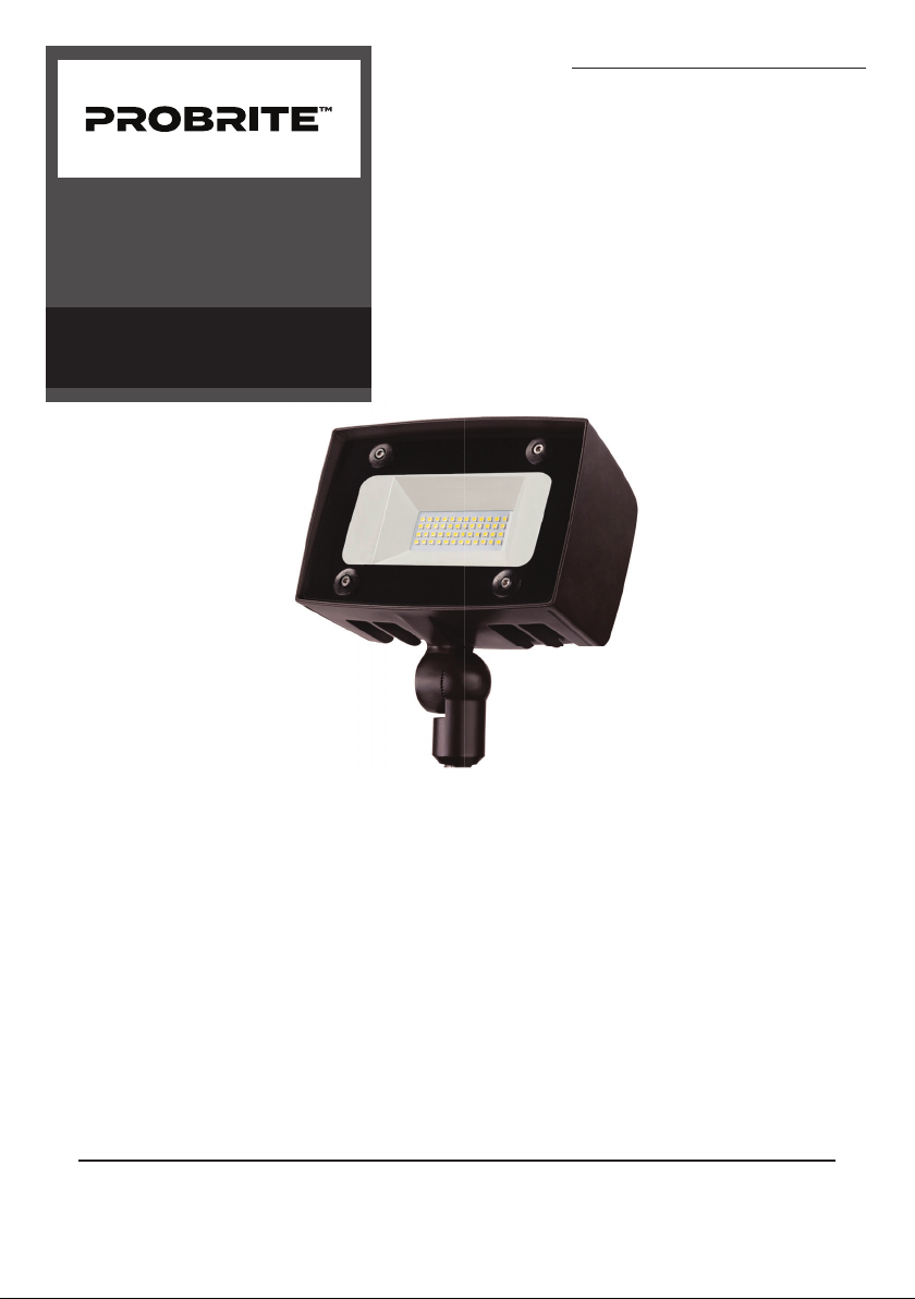
POWERFLOOD LED
ARCHITECTURAL
FLOOD LIGHT
INSTALLATION,
USAGE, & CARE GUIDE
Model No.
Mfr. SKU
PWRF20-4K-BZ
103-04400005-1
Questions? / Missing Parts? / Need Accessories?
Before returning to the store, call or email PROBRITE
Customer Service 9am-5pm EST Monday to Friday.
1-844-507-5651
PROBRITE.COM
Visit us online anytime or call us to get information on our product range, download
detailed spec & photometric files, find product and mounting accessories, view
installation tutorials and videos, and learn about our DLC® rebate eligible products.
Page 2

Table of Contents
Pre-Installation
Table of Contents......................... 2
Safety Information....................... 2
Pre-Installation............................. 3
Planning Installation..................... 3
Specifications................................. 3
Tools Required................................ 3
Package Contents......................... 4
Installation.................................... 5
Operation...................................... 8
Care & Cleaning............................9
Troubleshooting........................... 9
Warranty........................................ 10
Hardware Included........................ 4
Safety Information
IMPORTANT
THIS PRODUCT MUST BE INSTALLED IN ACCORDANCE WITH THE APPLICABLE
NATIONAL ELECTRICAL CODE AND LOCAL BUILDING CODES BY A PERSON FAMILIAR
WITH THE CONSTRUCTION AND OPERATION OF THE PRODUCT AND THE HAZARDS
INVOLVED.
PRECAUTIONS
☐ Please read and understand this entire
manual before attempting to assemble,
install, or operate this light fixture.
☐ This light fixture requires a 120-277Volt
AC power source.
☐ Some codes require installation by a
qualified electrician.
☐ This light fixture must be properly
grounded.
☐ Make sure connections are secure
using wire nuts, crimp-on lugs or other
approved connecting devices
☐ This light fixture should be installed
outdoors to a wall or to the ground.
☐ This product may contain chemicals
known to be hazardous. Thoroughly
wash hands after installing, handling,
cleaning or otherwise touching the
product.
WARNING: Turn the power o at the circuit
breaker or fuse. Place tape over the circuit
breaker switch and verify power is o at the
light fixture.
WARNING: Risk of fire. Keep the lamp heads at
least 3 in. (76mm) from combustible materials.
CAUTION: Burn hazard. Allow the light fixture
to cool before touching.
NOTICE: Do not connect this fixture to a
dimmer switch.
NOTICE: FCC Regulations state that any
unauthorized changes or modifications to
this equipment not expressly approved by the
manufacturer could void the user’s authorization to operate this equipment.
PLANNING INSTALLATION
Before installing the light fixture, ensure that all parts are present. Compare parts with the
Hardware Included and Package Contents sections. If any part is missing or damaged, do
not attempt to assemble, install, or operate this light fixture.
Estimated installation time: 20 minutes
SPECIFICATIONS
Lumens (Light Output)
Watts (Power Consumption)
Replaces
Lumens/Watts (Efficacy)
Power Requirements (Input Voltage)
Light Color (CCT)
Dimmable
Operating Modes
2000 Lumens
20 Watts LED
70 Watt Metal Halide
100 lumens per watt
120-277VAC
4000 Kelvins (Bright White)
Non-Dimming (Do not wire to dimming switch)
Switch-Activated:
Flip switch to turn light fixture ON and OFF. Use
included light sensor cap on fixture's light sensor
to utilize this mode setting.
TOOLS REQUIRED
Safety
goggles
Silicone
Sealant
Wire strippers/
cutters
Work
gloves
Circuit tester
Ladder
INFORMATION: The device is tested and found to comply with Part 15 of the FCC Rules. Operation is subject
to two conditions: (1) This device may not cause harmful interference and, (2) this device must accept any
interference received, including any interference that may cause undesired operation.
These limits are designed to provide reasonable protections against harmful interference when the equipment is operated in a commercial environment.
2
Visit www.probrite.com/install for installation video tutorials and product support
3
Please call 1-844-507-5651 or email [email protected] for further assistance.
PROBRITE.COM
Page 3
Pre-Installation (continued)
Installation
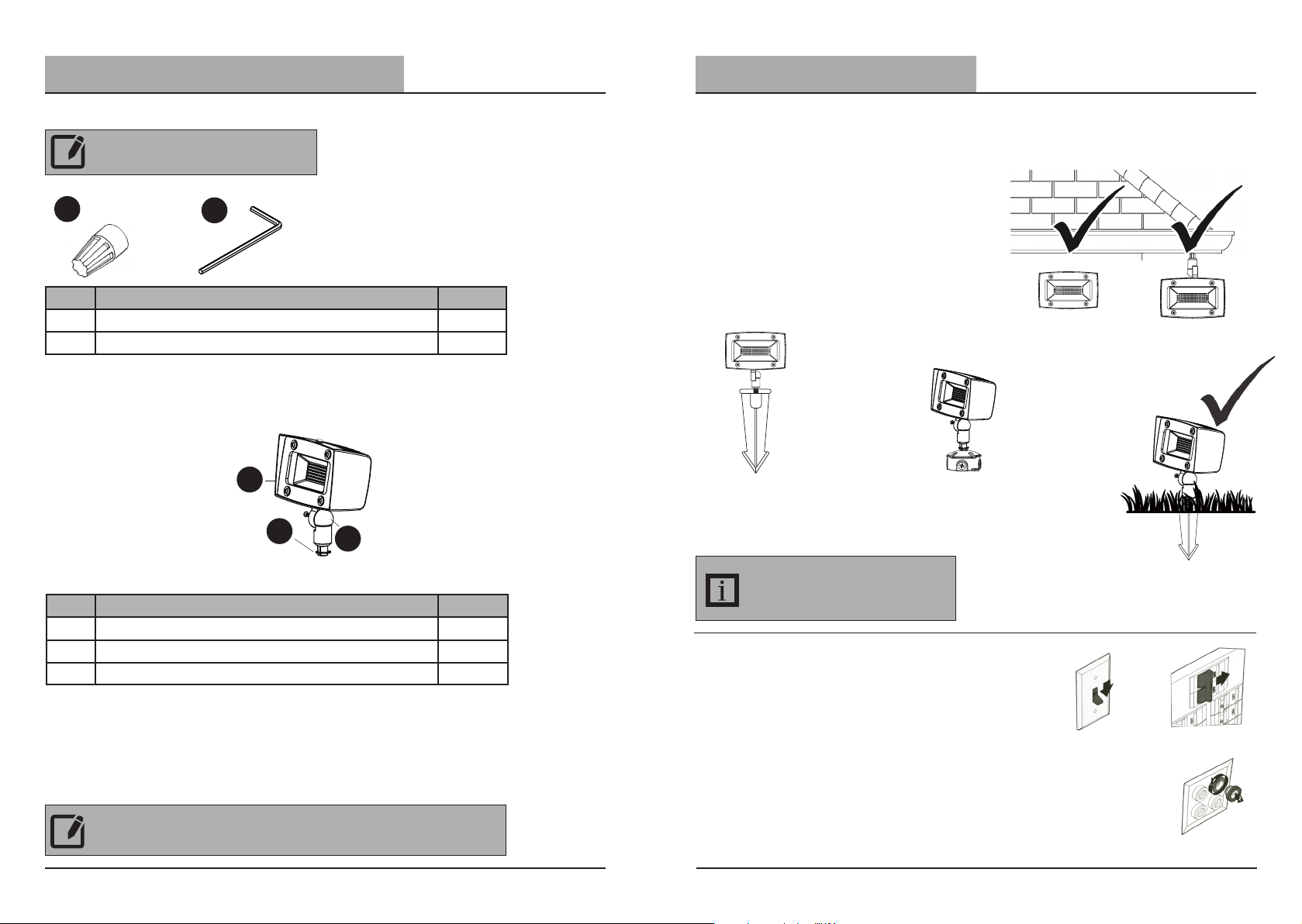
HARDWARE KIT
NOTE: Hardware not shown to actual size.
AA
Part Description Quantity
AA
Wire nut 3
BB
Allen key 1
BB
PACKAGE CONTENTS
A
C
B
For best results
1
☐ The fixture must be mounted using the
Swivel Knuckle into a domed cover plate
(not provided) on a junction box or via a
landscape post (sold separately).
☐ When installing two fixtures on one
switch, make sure the switch is rated for
at least a 1A inductive load.
☐ If using a dimming switch, use a 0-10V
dimmer.
Mounted to landscape post
(sold separately)
Mounted to domed cover
plate with center hole
Wall Mount
Eave Mount
(sold separately)
Part Description Quantity
Light fixture 1
A
B
1/2" Swivel NPS threaded knuckle mount 1
C
Knuckle mount tightening washer 1
NOTE: The junction box cover plate is not provided in the box. It is available separately
with your retailer.
4
Visit www.probrite.com/install for installation video tutorials and product support
IMPORTANT INFORMATION: Domed cover
plates for junction boxes, landscape posts,
and other mounting arms and accessories
are available. Please contact your retailer or
PROBRITE's customer support.
Shut electric power off
2
☐ At wall switch verify it is in the o position
(fig 1).
☐ At the main electrical panel turn o the
circuit breaker that supplies power to the
outlet box you are working on (fig 2).
☐ For screw-in type fuses unscrew the fuse
that supplies power to the outlet box you
are working on (fig 3).
Please call 1-844-507-5651 or email [email protected] for further assistance.
Ground Mount
(fig 1).
5
(fig 2).
(fig 3).
PROBRITE.COM
Page 4
Installation (continued)
Installation (continued)
Making the electrical connections
3
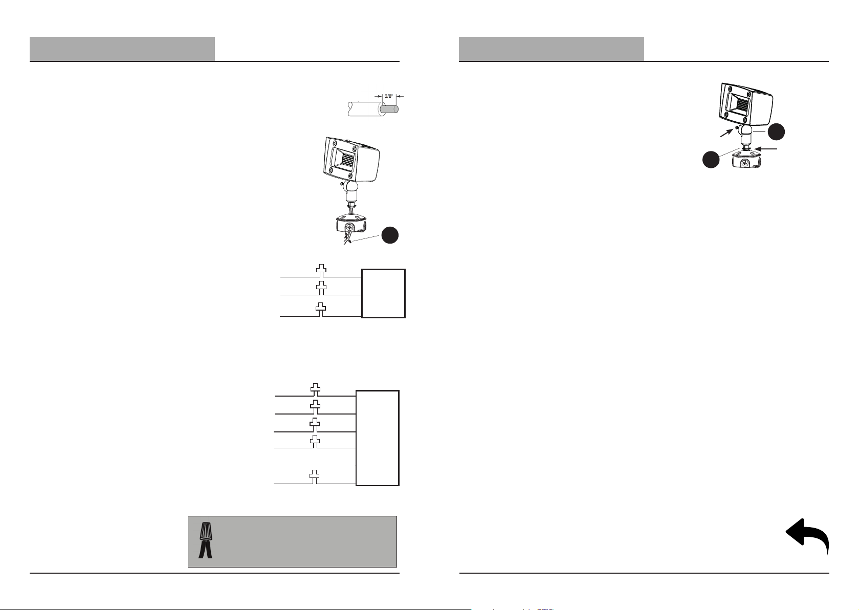
☐ If necessary, strip 3/8" of insulation from
junction box or fixture (A) wires (fig 1).
☐ Thread the wire through the domed cover
plate of the junction box (not provided) or
landscape post (not provided).
☐ Make wiring connections into the junction
box or post by following the wiring
instructions below.
ON/OFF Wiring (Non Dimming) Method:
☐ Connect fixture black wire to house black
wire, the (+) line, and fixture white wire
to house white wire, the (-) common by
twisting the exposed wires together and
using the wire nuts (AA). Ensure no loose
wires.
☐ Connect house ground wire to the green
fixture ground wire, by twisting the
exposed wires together and using the
wire nuts (AA).
(+) LINE
(-) COMMON
GROUND
(fig 1).
BLACK
WHITE
GREEN
AA
LIGHTING
FIXTURE
Securing the fixture and
4
adjusting orientation
☐ Secure the fixture to junction box or landscape
post by inserting the threaded swivel knuckle
mount (B) into the cover plate or landscape
post. (Fig. 1)
☐ Place the locking washer on the inside of the
domed cover plate and tighten the fixture to
the plate
☐ If applicable, plug all unused holes and seal
threads with silicone.
☐ Loosen the screw on swivel portion of the
knuckle (B) using the provided allen key (BB),
adjust the fixture to a suitable orientation, and
then tighten the screw (C). (Fig. 1)
Loosen the
screw here
to adjust the
orientation and
tighten it back
C
(fig 1).
B
Tighten the
knuckle handle
here and use
the lock
0-10V Dimmable Wiring Method:
☐ Connect fixture black wire to house black wire,
the (+) line, and fixture white wire to house
white wire, the (-) common by twisting the
exposed wires together and using the wire nuts
(AA). Ensure no loose wires.
☐ Connect house ground wire to the green
fixture ground wire, by twisting the exposed
wires together and using the wire nuts (AA).
☐ Connect the purple wire to the (V+) DIM
wire and the gray wire with (V-) DIM wire by
twisting the exposed wire together and using
the wire nuts (AA).
Visit www.probrite.com/install for installation video tutorials and product support
TIP: Hold stripped ends near each other and align any
frayed strands (do not twist wires).
Push the wires into wire nut (AA) and use your fingers
to twist the wire nut clockwise until tight. Check for
tightness by pulling wires.
6
(+) LINE
(-) COMMON
(+)DIM V+
(-)DIM V-
GROUND
BLACK
WHITE
PURPLE
GRAY
YELLOW
GREEN
LIGHTING
FIXTURE
TURN PAGE
For Operation Instructions
7
Please call 1-844-507-5651 or email [email protected] for further assistance.
PROBRITE.COM
Page 5
Operation
Troubleshooting
Turning lights ON/OFF
1
SWITCH
SWITCH-CONTROLLED
Switch-controlled operation enables the light fixture to turn ON and
OFF by flipping a standard light switch. To add automatic Dusk to
Dawn control or motion sensing external sensors like a photo-control,
motion-sensor or timer is required (sold separately).
☐ Once the fixture is installed, turn power
back on from the circuit breaker and
switch.
☐ Flip switch ON and OFF to ensure light
functions properly.
NOTE: This fixture is not dimmable, so it
is best to not wire to a dimming switch.
Care and Cleaning
☐ Shut o main power supply before cleaning the product. To prolong the original ap-
pearance, clean the light fixture with clear water and a soft, damp cloth only.
☐ Do not use abrasive cleaners or cleaners that contain alcohol. Do not apply paints,
solvents, or any other chemicals on this light fixture. They could cause a premature
deterioration of the finish and may void the warranty.
☐ Do not spray the light fixture with a hose or power washer.
CONTROLLED
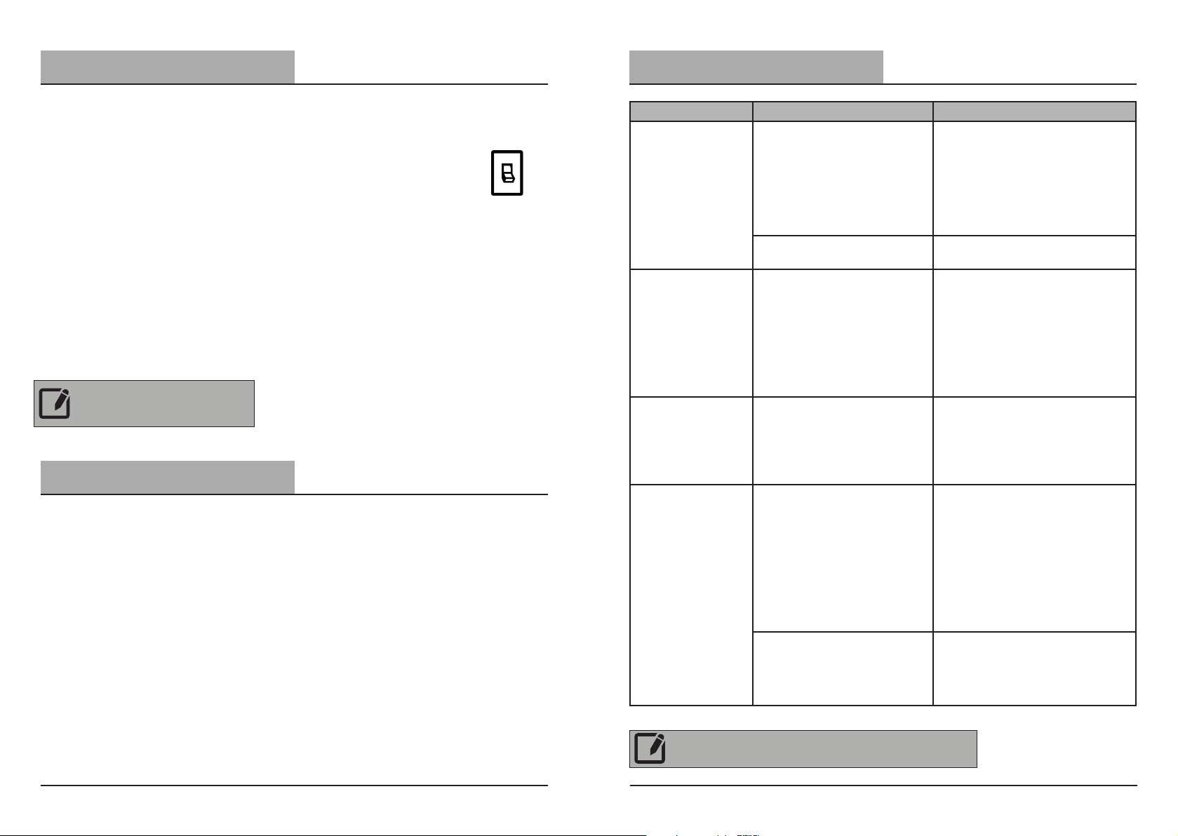
Problem Possible Cause Solution
Check if circuit breaker is tripped
Confirm wall switch is ON
Verify wiring to fixture is correct
(turn power o to fixture
beforehand)
Cover photocell. Wait several
seconds until fixture turns ON.
Relocate light fixture to a location
where there is no reflected light.
OR place the optional photocell
cover over the photocell light
sensor and use the wall switch to
turn the light ON and OFF.
Do not use a dimmer switch to
control the light fixture. Replace
the dimmer with a standard
ON/OFF wall switch.
Shine a flashlight into the light
sensor and wait a couple minutes.
If the light turns OFF, the fixture
should be moved to a location
with enough light in the daylight
hours for the light sensor to work.
OR place the optional opaque
cover over the photocell light
sensor and use the wall switch to
turn the light ON and OFF.
If the light does not turn o when
a flashlight is shined on the light
sensor for a few minutes, then
the sensor may be faulty. Please
contact customer service.
Light does not
turn ON
Light cycles
ON and OFF
continuously
Light
FLICKERS
Light stays ON
No power to the fixture
Fixture is sensing daylight
Photocell light sensor is sensing reflected light
The light fixture is wired
through a dimmer switch.
Light sensor is in a shaded
area
Light Sensor is faulty
8
Visit www.probrite.com/install for installation video tutorials and product support
NOTE: Photocell (B) may have a few minute delay, to reduce it's
sensitivity to sudden light changes. When testing shine a light/cover
the photocell for a few minutes to check if fixture functions properly
9
Please call 1-844-507-5651 or email [email protected] for further assistance.
PROBRITE.COM
Page 6

5-Year Limited Warranty
This is a limited warranty oered by Probrite for a period of five years from the date of purchase
to its customers. Probrite warrants to customers that the products will be free from defects
in material and workmanship. The obligation of Probrite under this warranty is limited to the
provision of replacement of products and is extended to the original purchaser of the product
on presenting valid purchase receipt or other proof of date of original purchase acceptable to
Probrite. The receipt is required for rendering the warranty performance. Any warranty claims
without original proof of purchase would not be accepted.
It should be noted that the warranty does not apply to Probrite products that have been
altered or repaired by unauthorized personnel, have been subjected to neglect, abuse, misuse
or accident or damages caused during shipping. Any other products not manufactured by
Probrite which have been supplied, installed and/or used in conjunction with Probrite products
are not covered under this warranty. Any damages caused by replacements bulbs, LEDs or
corrosion or discoloration of brass components are also not covered by this warranty.
Limitation of Liability:
In no event Probrite shall be liable for indirect, consequential, incidental or special damages, or
lost profits. Probrite is not liable for any claims or damage arising out of or connected with the
manufacture, sale, delivery, use, maintenance and repair or modification of Probrite products,
or supply of any replacement parts that, exceed the purchase price of Probrite products giving
rise to a claim. Labor charges to remove or install the fixtures will not be accepted.
To Claim:
Please contact PROBRITE customer service at 1-844-507-5651 or email support@PROBRITE.
com and include your name, address and contact number, along with a copy of the purchase
receipt and a brief description of the problem.
10
Visit www.probrite.com/install for installation video tutorials and product support
11
Please call 1-844-507-5651 or email [email protected] for further assistance.
PROBRITE.COM
Page 7

Questions? / Missing Parts? / Need Accessories?
Before returning to the store, call or email PROBRITE
Customer Service 9am-5pm EST Monday to Friday.
1-844-507-5651
PROBRITE.COM
RETAIN THIS MANUAL FOR FUTURE USE
Para las translaciones en español,
visit www.probrite.com/install
 Loading...