

Probrite NOVA100-PC-4K-BZ, NOVA150-PC-4K-BZ Installation, Usage, & Care Manual
NOVA COMMERCIAL
LED AREA LIGHT
INSTALLATION,
USAGE, & CARE GUIDE
Model No.
Mfr. SKU
NOVA100-PC-4K-BZ
NOVA150-PC-4K-BZ
103-05800017-1
103-05900017-1
Questions? / Missing Parts? / Need Accessories?
Before returning to the store, call or email PROBRITE
Customer Service 9am-5pm EST Monday to Friday.
1-844-507-5651
support@PROBRITE.com
PROBRITE.COM
Visit us online anytime or call us to get information on our product range, download
detailed spec & photometric files, find product and mounting accessories, view
installation tutorials and videos, and learn about our DLC® rebate eligible products.
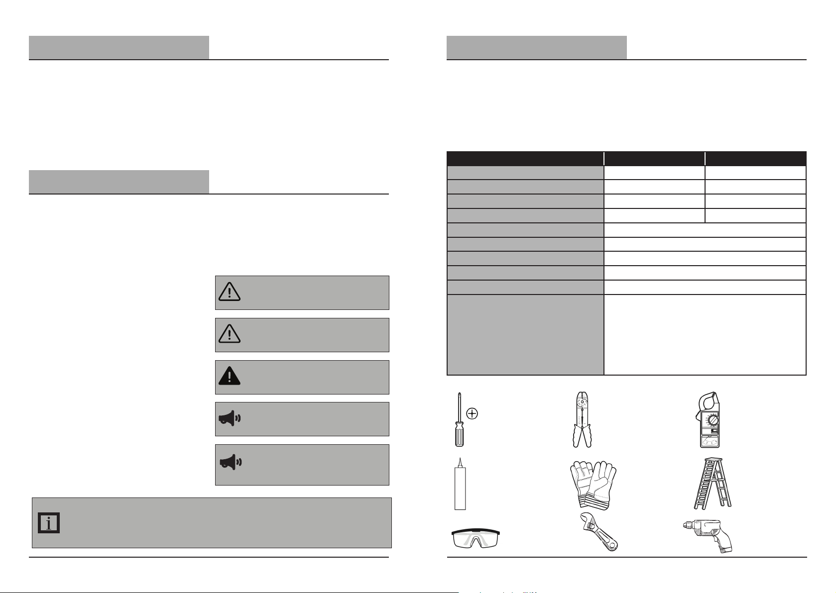
Table of Contents
Pre-Installation
Table of Contents......................... 2
Safety Information....................... 2
Pre-Installation............................. 3
Planning Installation.................... 3
Specifications................................. 3
Tools Required............................... 3
Hardware Included........................ 4
Package Contents......................... 4
Installation..................................... 5
Installation (Extension Arm)...... 10
Operation ..................................... 14
Care & Cleaning........................... 15
Troubleshooting.......................... 15
Warranty....................................... 16
Safety Information
IMPORTANT
THIS PRODUCT MUST BE INSTALLED IN ACCORDANCE WITH THE APPLICABLE
NATIONAL ELECTRICAL CODE AND LOCAL BUILDING CODES BY A PERSON FAMILIAR
WITH THE CONSTRUCTION AND OPERATION OF THE PRODUCT AND THE HAZARDS
INVOLVED.
PRECAUTIONS
☐ Please read and understand this entire
manual before attempting to assemble,
install, or operate this light fixture.
☐ This light fixture requires a 120-277Volt
AC power source.
☐ Some codes require installation by a
qualified electrician.
☐ This light fixture must be properly
grounded.
☐ Make sure connections are secure
using wire nuts, crimp-on lugs or other
approved connecting devices
☐ This light fixture should be installed
outdoors to a wall or a pole.
☐ This product may contain chemicals
known to be hazardous. Thoroughly
wash hands after installing, handling,
cleaning or otherwise touching the
product.
INFORMATION: The device is tested and found to comply with Part 15 of the FCC Rules. Operation is subject
to two conditions: (1) This device may not cause harmful interference and, (2) this device must accept any
interference received, including any interference that may cause undesired operation.
These limits are designed to provide reasonable protections against harmful interference when the
equipment is operated in a commercial environment.
WARNING: Turn the power o at the circuit
breaker or fuse. Place tape over the circuit
breaker switch and verify power is o at the
light fixture.
WARNING: Risk of fire. Keep the lamp heads at
least 3 in. (76mm) from combustible materials.
CAUTION: Burn hazard. Allow the light fixture
to cool before touching.
NOTICE: For dimming use a 0-10V dimming
switch
NOTICE: FCC Regulations state that any
unauthorized changes or modifications to
this equipment not expressly approved by the
manufacturer could void the user’s authorization to operate this equipment.
PLANNING INSTALLATION
Before installing the light fixture, ensure that all parts are present. Compare parts with the
Hardware Included and Package Contents sections. If any part is missing or damaged, do
not attempt to assemble, install, or operate this light fixture.
Estimated installation time: 20 minutes
SPECIFICATIONS
MODEL NOVA 100W NOVA 150W
Lumens (Light Output)
Watts (Power Consumption)
Replaces
Lumens/Watts (Efficacy)
Power Requirements (Input Voltage)
Light Color (CCT)
Dimmable
Surge Protection
Optic Distribution Type
Operating Modes Dusk-to-Dawn:
12000 Lumens 18000 Lumens
100 Watts LED 150 Watts LED
250 Watt PSMH 400 Watt Metal Halide
120 lumens per watt 120 lumens per watt
120-277VAC
4000 Kelvins (Bright White)
Dimming (Use with 0-10V dimming switch)
10kV
Type IV
Automatically turns light fixture ON during night
and OFF during day.
Switch-Controlled:
Flip switch to turn light fixture ON and OFF. Use
included light sensor cap on fixture's light sensor
to utilize this mode setting.
TOOLS REQUIRED
Phillips
Screwdriver
Silicone
Sealant
Safety
goggles
Wire strippers/
cutters
Work
gloves
Wrench Power
Circuit tester
Ladder
Drill
2
Visit www.probrite.com/install for installation video tutorials and product support
3
Please call 1-844-507-5651 or email support@probrite.com for further assistance.
PROBRITE.COM

Pre-Installation (continued)
Installation
HARDWARE KIT
NOTE: Hardware not shown to actual size.
AA
BB
CC
EE FF GG HH
Part Description Quantity
Extension Arm 1
AA
Wire nut 3
BB
Flat Washers 3
CC
Adapter plate (For round pole) 1
DD
EE
Photocell black cover label 1
FF
Allen Key 2
GG
Hex Head Lag bolts 2
HH
Bolster plate 1
PACKAGE CONTENTS
E
D
B
DD
For best results
1
☐ The fixture can be mounted in the
following ways:
☐ Swivel Slipfitter Knuckle Arm
Mount: Use the default swivel
slipfitter knuckle on a 2-3/8" to
2-1/2" (O.D) round pipe, or fit to
standard tenon arms for ground,
pole, or wall mounting (tenon arms
sold separately).
☐ Extension Arm Mount: The fixture
can also be mounted directly on
a square or round pole surface, or
direct to a wall, using the extension
arm supplied separately in the
package.
☐ Install on ground as a flood light or 12-30
feet above the ground for pole and wall
mounting.
☐ Place the photocell (provided separately
in the box) on the receptacle on top of
the fixture and rotate in the direction of
the arrow marked on the photocell.
☐ When mounting fixture, for Dusk to
Dawn operation, make sure the photocell
orientation is at the top for wall mount,
in an area that receives daylight and not
too close to reflective surfaces.
Swivel Slipfitter
Knuckle Arm Mount
Works on 2-3/8" to 2-1/2"
(O.D) round pipe, or fit to
standard tenon arms
Square pole
or wall mounting
Extension Arm Mount
☐ When installing two fixtures on
one switch, make sure the switch
is rated for at least a 1A inductive
load.
☐ The fixture may or may not be
wired to a dimming switch.
Round pole
(use included
adapter plate)
A
Part Description Quantity
Light Fixture 1
A
Photocell NEMA 3-Pin Receptacle 1
B
2-3/8" Swivel Slipfitter Knuckle Mounting Arm 1
C
D
Extension Arm Mount 1
E
120-277V NEMA 3-Pin Twist-lock Photocell 1
4
Visit www.probrite.com/install for installation video tutorials and product support
B
C
Shut electric power off
2
☐ At wall switch verify it is in the o
position (fig 1).
☐ At the main electrical panel turn o the
circuit breaker that supplies power to
the outlet box you are working on (fig
2).
☐ For screw-in type fuses unscrew the fuse
that supplies power to the outlet box
you are working on (fig 3).
Please call 1-844-507-5651 or email support@probrite.com for further assistance.
(fig 1).
5
(fig 2).
(fig 3).
PROBRITE.COM
 Loading...