

ProBoat SUNRISE 24 Instruction Manual

Specifications
Length .......................................................................................................... 24 in (609.6 mm)
Beam .............................................................................................................. 6 in (152.4 mm)
Main Sail Area.............................................................................................. 199 in
2
(1284 cm2)
Jib Sail Area.................................................................................................. 87 in
2
(561.3 cm2)
Mast Height .................................................................................................. 36 in (914.4 mm)
Overall Height .............................................................................................. 47 in (1193.8 mm)
Radio System.......................................................................... JR AM Beat Gear (RTR Version)
Instruction Manual
™

2
Thank you for purchasing the ProBoat™Sunrise™24 Ready-To-Run
sailboat. This sailboat has been designed to provide many hours
of scale sailing pleasure, without the long hours of assembling
that is usually associated with a model R/C sailboat. The Sunrise 24
can be completed in less than an hour of assembly time.
No Building!
The Sunrise 24 comes almost completely assembled. Its durable
molded fiberglass hull has been painted for your convenience.
You will only need to finish rigging the sails and attach the rudder.
The detailed instructions, photos, and glossary at the back of
the manual will allow you to easily complete the assembly. A
box is provided for each step of the manual so that you can check
off that particular section when complete.
Radio
RTR Sunrise (PRB2170)
Your RTR Sunrise comes with the JR Beat Gear 2-channel AM
radio system installed. Please refer to the manual of the Beat
Gear radio system before attempting to sail your Sunrise. This
manual will answer any questions that you may have regarding
the radio system.
ARR Sunrise (PRB2171)
Your ARR Sunrise arrives ready for radio installation and completely
assembled. A 2-channel radio system is needed to complete it.
Please follow your radio system instructions for the set up. The sail
servo arm is included with the Sunrise, and the rigging line has
already been attached to the sail servo arm to make installation
easier. Please refer to the box art to see a photo that shows how
the radio box should appear when installation is complete.
Introduction .............................................................................................................................................................................................. 2
Section 1—Inspection of Sunrise 24 ........................................................................................................................................................ 2
Section 2—Completing the Boat............................................................................................................................................................ 3-8
Section 3—Installation of Batteries for Radio Transmitter and Receiver .................................................................................................. 9
Section 4—Checking the Radio System.................................................................................................................................................... 9
Section 5—Sailing Tips ...................................................................................................................................................................... 9-10
Basic Glossary..........................................................................................................................................................................................11
Replacement Parts .................................................................................................................................................................................. 12
Plastic Parts ............................................................................................................................................................................................13
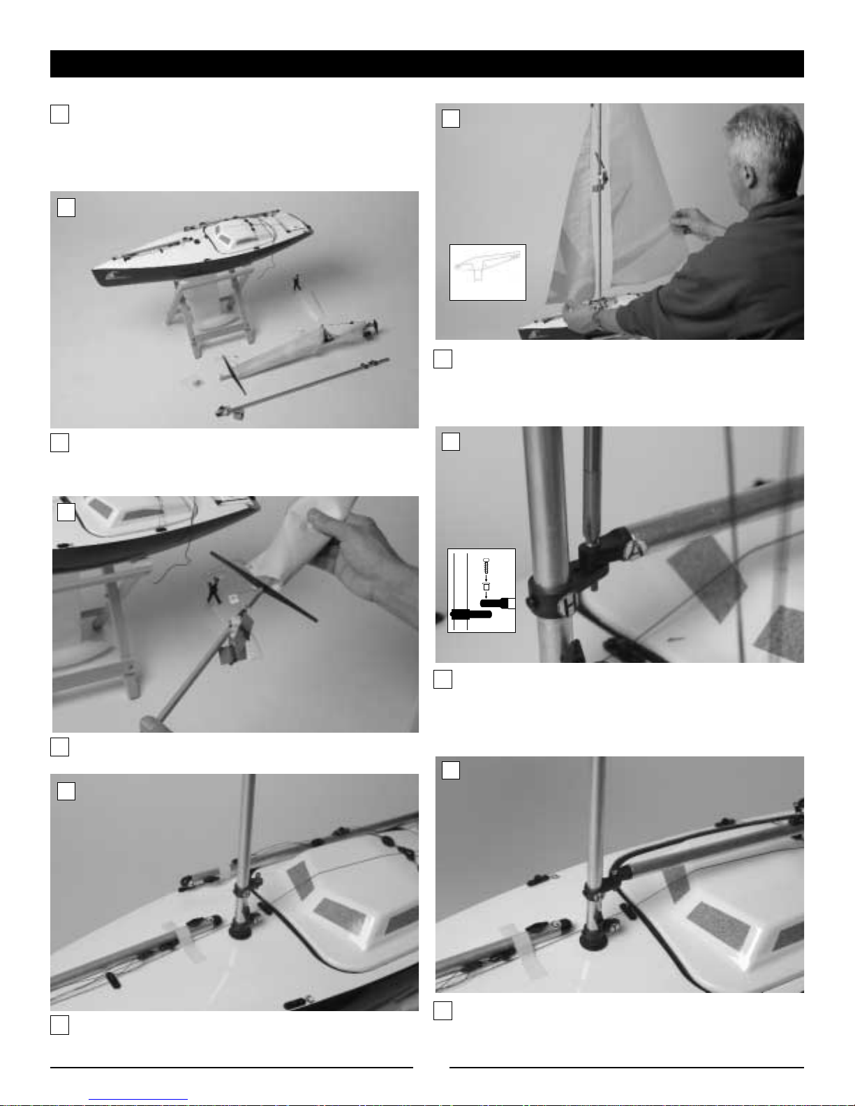
Carefully remove the boat, boat stand, and radio transmitter
from the box. Inspect the boat and make certain that no
damage is present. If you notice any damage, please contact
the ProBoat retailer where it was purchased.
Introduction
Table of Contents
Section 1—Inspection of Sunrise 24
3
Section 2—Completing the Boat
Locate the cardboard box that contains the sails and hardware.
Remove the two-piece mast (one part of the mast will have
the sails rolled around them). Also remove the rudder, boat
stand, and small hardware bag.
Carefully place the hull on the boat stand. Note the two-piece
mast, rudder, and hardware bag.
Insert the joined mast into the hull as shown above.
Carefully unroll the sails from the mast. The main sail will be
attached to the top of the mast at the crane, and the jib sail will
be attached at the triangular shaped spreader.
Locate the main sail boom. It will have an "A" on one end.
After removing the brass eyelet and the included screw from
the gooseneck labled "H", install the boom and secure it
as shown.
Join the mast halves as shown.
View of previous completed step
Crane
1
2
3
4
5
6
4
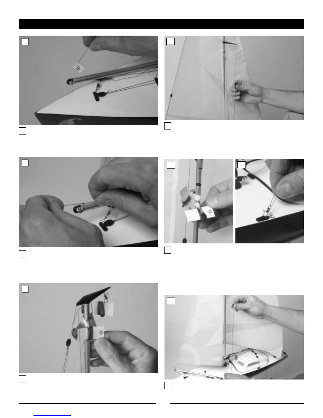
Locate the jib sail boom. It will have a "B" sticker on one end.
Find the rig line from the jib sail that is marked "B". Remove
the tape from the line and insert it through the eyelet.
After pulling the rig line through the eyelet, make certain that
the space between the bottom of the sail and the sail boom is
approximately
1
/2" to 1" (see photo 23). Now, tie a secure
knot in the line.
Locate the jib stay on the rigging line. Pull up carefully on the
jib stay to adjust the tension as shown until there is no slack
in the line, but the mast is still completely vertical.
Carefully unwrap the top rigging line that is marked "C."
Insert the line into the spreader as shown.
Note: The spreader has a small factory made slot in the outer
hole. The inner hole will not be used. This makes it much
easier to insert the line into. You can simply push the rigging
line through the slot.
After feeding the rigging line through the spreader, open the
rigging clip and attach it into the eye plate marked "C." Close
the wire clip. Repeat this step with the lower rigging line
that is marked "C." This lower rigging line is located directly
below the black spreader, and it will also clip to the eye plate
that is labeled "C." When you have completed this step, both
rigging lines marked "C" will be clipped to the eyelet marked "C."
Section 2—Completing the Boat (continued)
Lower
Rigging
Line
7
8
9
10
11
12
13

5
Locate the top rigging line that is marked "D." Carefully unwrap
the line. After feeding the rigging line into the spreader
proceed to the eyelet labeled “D” and clip into the eyelet
(refer to photo 16).
Locate the lower rigging line just below the spreader marked "D."
Carefully unwrap the rigging line.
Clip the rigging line into the eyelet marked "D" as shown. At
the end of this step, both rigging lines that were marked "D"
will be clipped to the above eyelet marked "D."
Locate the jib stay on the rigging line and pull up carefully on
the jib stay to adjust the tension slightly taught as shown.
Again, there should be no slack but the mast should remain
completely vertical.
Locate the rigging line at the top of the mast marked "E."
Carefully unwrap the line.
Proceed directly to the eye plate on the rear of the hull
marked "E." Clip the rigging line as shown.
Section 2—Completing the Boat (continued)
14
15
16
17
18
19
Spreader
 Loading...