

Page 1

®
Formula FASTech 26 Nitro
Owner's Manual
Specifications
Length ......................................................................................26.75 in (679mm)
Beam ........................................................................................8.375 in (213mm)
Engine ................................................... Water-Cooled Marine Nitro with Tiger Drive
Radio System...................................................... Pro Boat 27MHz AM Radio System
Formula, FASTech and Solar Reactor trim scheme are trademarks of Formula/Thunderbird Products.
Used under license by Horizon Hobby, Inc.
Page 2

Table of Contents
Table of Contents .................................................................................................2
Introduction .........................................................................................................2
General Guidelines ............................................................................................... 3
Additional Required Items ..................................................................................... 3
Suggested Field Equipment and Supplies ................................................................. 4
Contents .............................................................................................................4
Installing the Receiver and Transmitter Batteries .................................................. 5–6
Adjusting the Transmitter ...................................................................................... 7
Checking the Radio System ............................................................................... 7–8
Handling Adjustment ............................................................................................ 9
Range Checking the Pro Boat Radio System ........................................................... 10
Filling the Fuel Tank ............................................................................................ 10
Starting the Nitro Engine ................................................................................ 11–12
Testing Your Boat in the Water ............................................................................. 13
Maintenance ................................................................................................. 13–14
Troubleshooting Guide ......................................................................................... 15
Formula FASTech Nitro Replacement Parts ............................................................. 16
Parts Identification ............................................................................................. 17
Warranty Information ..................................................................................... 18–19
Introduction
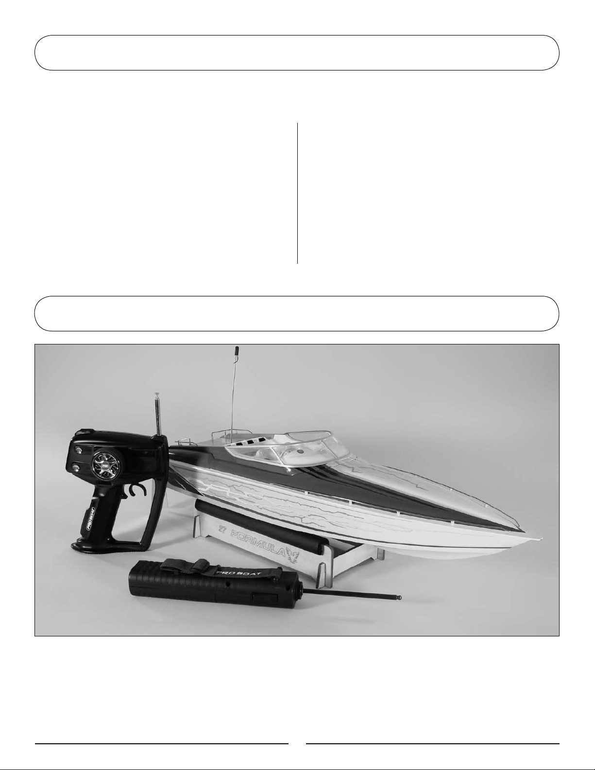
Congratulations on the purchase of your
Pro Boat® Formula FASTech Deep-V Nitro.
You are just minutes from one of the most
thrilling experiences that the radio control
hobby has to offer.
The Pro Boat Formula FASTech is a
professionally built, ready-to-run fiberglass
model of one of Formula boat's flagships. It
is meticulously detailed with Formula Boats'
Platinum Series Solar Reactor trim scheme.
Read this owner’s manual thoroughly.
You also need to read the included engine
manual, along with the Pro Boat pistol-grip
radio system manual.
It is very important that you operate this
boat responsibly. With proper care and
maintenance, you will be able to enjoy your
Formula FASTech for many years to come.
Carefully unpack the Formula FASTech and
examine the boat and its contents. The
contents contain the Formula FASTech RTR
with radio installed, a boat stand, hand-held
starter, and the Pro Boat pistol-grip radio
transmitter. If you are missing any of these
items or notice any damage, immediately
contact the place of purchase.
2
Page 3

General Guidelines
It is important that you read and follow
this instruction manual, along with the Pro
Boat radio system manual and the Nitro
engine manual, before you run this exciting
boat. Failure to read and understand the
manual could result in personal injury,
property damage or permanent damage to
your boat. It is also important to run your
boat responsibly. With proper care and
maintenance, you will be able to proudly
enjoy your Formula FASTech for many years
to come.
When operating the boat, stay clear of
people, full-scale boats, stationary objects
and wildlife. It is preferable to operate the
Formula FASTech in low wake, low wind
conditions.
Before you operate your model, make sure
that your radio frequency is clear. If someone
is operating on the same frequency, both
models could go out of control, possibly
causing damage to the models or to others.
Check all of the hardware, manifold, pipe and
propeller for security before and after each
run.
If at any time while operating your model
you sense any abnormal function, end your
operation immediately. Do not operate your
boat again until you are certain the problem
has been corrected. Always stay clear of
the propeller.
Additional Required Items
Although the Formula FASTech comes fully assembled and ready for action, you will need a few
additional items in order to run your boat. You will need the following:
• BlueThunder™20%Fuel(quart)
(DYN2320)
• 500ccFuelBottle(DYN2003)or
• FastTap™QuartBottleSpout(DYN2009)
• GlowPlugWrench(DYN2510)
• Ni-CdGlowDriver(DYN1925)
• 12AAalkalinebatteries(8forthe
transmitter and 4 for the receiver)
• 7.2VSub-CBatteryPack(DYN1005)
3
Page 4
Suggested Field Equipment and Supplies
In addition to the items needed to run the Formula FASTech, we recommend that you carry the
following in your field box:
• EngineTuningScrewdriver(DYN2775)
• ReplacementGlowPlugs
(DYN2508 or DYN2500)
• Hexdriver/Allenwrench(1.5mmand
2.5mm)
• Cablegreasetolubricatedriveshaft
(PRB0100, PRB0101)
• Cleantowelsandrags
• AAalkalinebatteries
• Adjustablewrench(small)
• 10mmwrench(2)
• Extrapropellers
• Threadlockingcompound
• 7.2Vbattery(DYN1185)forelectricstarter
• Batterycharger(DYN4051)forelectric
starter battery
Contents
• AssembledFormulaFASTechRTR
• ProBoatradiotransmitter
• Prebuiltboatstand
• Hand-heldstarter
4
Page 5
Installing the Receiver and Transmitter Batteries
Receiver Batteries
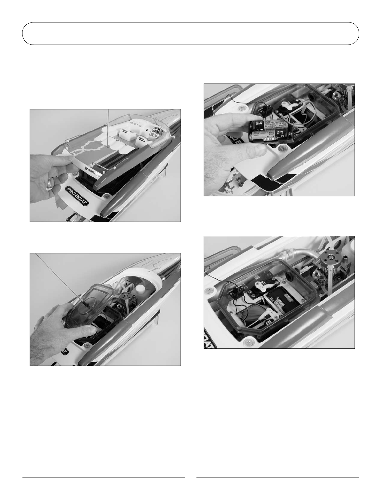
1. Lift the cockpit from the hull from the
rear. It is held in position using magnets
so there will be a little resistance when
lifting upward.
2. Lift the radio compartment hatch from the
radio compartment.
3. Remove the dry cell battery holder from
the radio box. Install four AA alkaline
batteries as shown with respect to polarity.
4. Place the battery holder back into the
radio box. Confirm the switch is in the "off"
position after installing the batteries.
5
Page 6
Installing the Receiver and Transmitter Batteries
5. Place the radio box cover back onto the
radio box. Make sure it snaps tighly onto
the radio box to ensure a water-tight seal.
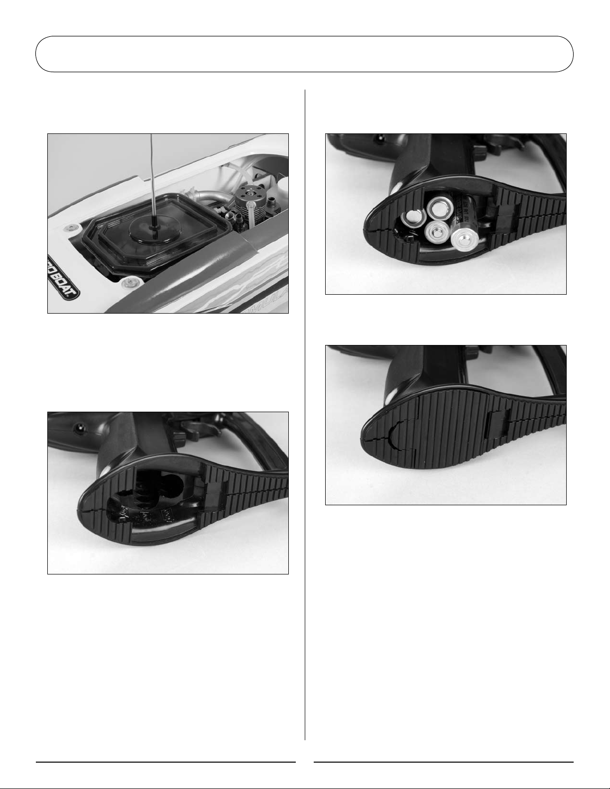
Transmitter Batteries
1. Remove the transmitter from the box.
3. Install the AA batteries into the
transmitter. Be aware of the proper
polarity when inserting the batteries.
4. Replace the battery cover to complete the
battery installation.
2. Remove the battery cover on the bottom
of the transmitter.
5. Turn on the radio to ensure the batteries
have been installed correctly. All 3 LEDs
will illuminate, indicating fully charged
batteries.
6. Turn the radio off to prevent accidentally
running the voltage out of the batteries.
6
Page 7

Adjusting the Transmitter
Note: Refer to the radio instructions for
specific information on transmitter setup.
Adjust both the Throttle and Steering trims to
the center position.
Turn on the transmitter, then the receiver
power switch.
Throttle
Trim
Adjust the rudder trim knob so that the
rudder is centered prior to operation. You
may adjust this control to make the boat run
straight during operation.
Steering
Trim
Checking the Radio System
Ensure the antenna is properly placed
through the antenna tube. It may be
necessary to slightly pull the antenna
tube out to make certain the radio range
is sufficient.
7
Page 8

Checking the Radio System
The rudder control arm should move toward
the front of the boat when right input is
given. Conversely, when left input is given,
the control arm should move toward the back
of the boat.
Right Turn
Right Turn
8
Page 9

Handling Adjustment
Operate your Formula FASTech in low to
medium wake conditions to avoid having
problems with the boat overturning. If
the conditions are questionable, adjust
the prop strut up a bit (which makes the
propeller point more downward) to reduce
the likelihood of having the boat overturn.
The motor mount is slotted to allow you to
move the motor slightly when adjusting the
propeller strut. Adjust the propeller strut
down (which angles the propeller's trailing
edge upwards creating up-trim) for maximum
speeds. This adjustment will limit the
boat's turning ability but top end speed will
increase. You can also carefully bend the trim
tabs upwards to increase speed.
You may also turn the dual rate dial down
to reduce rudder travel in rough water
conditions or for inexperienced boaters.
Steering Dual
Rate
Loosen to
Adjust
Propeller Strut
9
Page 10

Range Checking the Pro Boat Radio System
Before the first run of the Formula FASTech,
range check the radio for proper operation
and ensure proper control movement of the
rudder and throttle. Also confirm that the
antenna on the boat is extended properly and
that all batteries are in working condition.
Note: It is a good idea to range check prior
to operating your boat after any repair,
installation of new batteries, or at the
beginning of each boating session.
With the radio system turned on (transmitter,
then the receiver) and the transmitter
antenna down (engine off), walk away from
the boat and confirm that you have control
from at least 20 yards.
If everything appears to be operating
correctly, raise the antenna and start the
engine (refer to Section 5 of this manual and
to the separate Nitro engine manual). Place
theboatinthewaterandrunit(atabout1⁄3
throttle) close to the shoreline. If everything
is operating properly, you can begin to run
the boat faster and further away from the
shoreline.
Filling the Fuel Tank
We recommend that you use Blue Thunder
20%fuel.Formaximumperformance,we
recommend Blue Thunder Race Formula. Blue
Thunder fuels are specifically formulated for
excellent power and engine protection.
Locate the fuel tank inside the cockpit area
and unscrew the lid. Use either the DYN2009
Fast Tap quart bottle spout that has been
attached to the quart of fuel or the DYN2003
Fuel Bottle to fill the fuel tank with your
selection of Blue Thunder fuel. After you have
filled the fuel tank and re-installed the lid,
wipe away any excess fuel that may have
been spilled inside the hull or elsewhere on
the boat. Immediately seal the fuel container
by putting the lid back on after refueling in
order to protect the fuel from moisture.
10
Page 11

Starting the Nitro Engine
Water-Cooled Engine
Because the Nitro engine is water-cooled,
make sure that you do not run the engine
for an extended amount of time outside of
the water. Continuously monitor the water
outlet when the boat is running in the water
to make sure that the water is exiting the
water outlet. If the water does not reach the
head to cool it, the engine will overheat and
fail. This could cause permanent damage to
the engine.
Pro Mix Carburetor
Richer
High-Speed
Needle Valve
Idle
Adjustment
Screw
Low-Speed
Needle Valve
Hand-Held Starter
1. Fully charge a 7.2V sub-C battery pack and
install it in the starter as shown.
2. Slide the starting wand (which is stored
inside the battery cover) into the end of
the starter, then replace the battery cover.
Higher Idle
Leaner
The Nitro engine comes equipped with the
Pro Mix Carburetor. Each Pro Mix Carburetor
is pre-adjusted at the factory. This setting
shouldbeapproximately3-1⁄2turnsopen
forthehigh-speedand2-1⁄2turnsopenfor
the low-speed needle. This should give you a
slightly “rich” mixture of fuel to the engine.
This setting is the safest way to break in your
engine. For further details regarding the Pro
Mix Carburetor, please consult the included
engine manual.
Adjust the throttle trim on the transmitter
so that the throttle barrel is 1/8-inch
(3mm) open.
11
Page 12

Starting the Nitro Engine
3. Turn on your radio system and attach a
fully charged glow igniter (DYN1925) to
the glow plug. Insert the starting wand
into the Tiger Drive and actuate the
starting switch until the engine begins to
run. If the engine does not start, place
your index finger over the carburetor and
actuate the starter until you see fuel enter
the carburetor through the fuel line.
Note: Stop operation immediately if the
engine enters a hydro-locked condition, as
serious engine damage may occur. Remove
the glow plug, invert the boat and operate
the starter to remove raw fuel before
resuming operation.
You may have to “blip” the throttle on the
transmitter (applying throttle on/off) while trying
to start the engine. New engines are harder
to start because of the tight piston/sleeve fit.
Never start an engine at more than 1/2 throttle,
as this will cause over-revving, which may cause
premature wear and breakage.
Breaking In Your Engine
During break-in, the low-speed needle should
be slightly rich and the high-speed needle
should be very rich. After a few tanks of
fuel, begin to lean the engine out. Adjust the
high-speedneedle1⁄16ofaturnatatime.It
generally takes about five to six tanks of fuel
before you want to lean out the engine until it
supplies good power. Do not skip this process
of break-in. Failure to follow this procedure
could damage your new engine. For further
details on breaking in your engine, please see
the separate engine instruction manual.
Note: It is common for an ABC engine
to go through a glow plug or two during
break-in.
Needle Settings
When adjusting the settings, always adjust
theneedlesinsmallincrements,about1⁄8of
a full turn at a time. Do not set the engine
too lean, as it shortens the life of the engine.
After you have attained the correct needle
settings, the engine will have a strongsounding, high-pitched whine at full speed,
and a thin trail of blue/white smoke will come
from the exhaust.
The low-end needle adjustment determines
how the engine transitions from idle to full
throttle. Once the high-speed needle is set,
adjust the low-end needle clockwise until a
smooth transition is obtained, then back it
out 1/4 turn.
Idle Adjustment
During the first tank of fuel, advance the
idle via the idle adjustment screw more than
normal to prevent stalling at idle due to the
rich fuel mixture for break-in. Pinch the fuel
line nearest the carburetor to stop the engine.
The last setting to set is the idle screw. To
obtain a higher idle, turn the idle screw
clockwise; for lower idle, turn the idle screw
counterclockwise.
12
Page 13

Testing Your Boat in the Water
Make sure the radio is "ON". Test the radio
system for proper operation and then
carefully place the boat in the water. Pilot
the boat at slow speeds, staying close to
the shoreline to ensure you have good
control and that the boat is functioning
correctly. Be certain to avoid all objects in
the water at all times.
Maintenance
Lube the gears inside the Tiger drive with
waterproof grease every 30 hours of use.
Check all screws for tightness after each run.
Lubrication
It is important to lubricate the flex shaft
of the Formula FASTech with silicone cable
grease after every two hours of operation.
Do not forget to do this or flex shaft damage
can occur. You can purchase this silicone
grease at your local hobby store (PRB0100 or
PRB0101). To lubricate the drive shaft, follow
these simple instructions.
Once you feel comfortable with the control of
your boat, it is safe to go further away from
the shoreline and at faster speeds.
1. Carefully note how the drive shaft and
prop are presently installed. This is
important so that when you have finished
lubricating the drive shaft, you can
correctly re-install it.
13
Leave a 1mm-2mm
gap here to allow for
flexshaft shrinkage
under load.
Page 14

Maintenance
2. Loosen and remove the 1.5mm setscrew
that holds the propeller shaft. Remove the
propeller and shaft from the aluminum strut.
4. Carefully pull the ferrule away from the
stuffing tube. You will need to pull at an
angle to clear the aluminum strut.
5. Clean any residue off of the flexshaft
and liberally lubricate the entire length
of the flex shaft with silicone cable grease
as shown.
3. Insert a hex driver into the hole located
on the flywheel to lock the crankshaft in
place. Then use a 10mm wrench to loosen
the collet nut.
6. Carefully re-install the flex shaft and
nylon bushing, making certain that you
correctly tighten the collet nut. Next,
re-install the drive shaft and propeller and
tighten the setscrew on the flat of the
drive shaft. Use threadlocking compound
to secure the setscrew.
Note: Running the Formula FASTech 26
Nitro RTR in salt water could cause some
parts to corrode. If you run the boat in salt
water, rinse it thoroughly in fresh water
after each use and lubricate the drive
system. Because of its corrosive effects,
running RC boats in saltwater is at the
discretion of the modeler.
14
Page 15

Troubleshooting Guide
Problem Possible Solution
Engine will not start Check needles and make changes back to factory settings if necessary
Improper needle setting
Out of fuel
Improper fuel
Improper glow plug
Glow igniter not charged
Dead glow plug
Flooded engine
Engine starts, then dies Pressure line blocked or unhooked
Reset needles to baseline setting
Improper needle settings
Leaking exhuast manifold gasket
Leaking exhaust coupler
Engine starts and runs for Bad glow plug
several minutes, then dies Idle speed set too low
Improper needle settings
Glow plug failed
Lean mixture setting
15
Page 16

Formula FASTech Nitro Replacement Parts
In the event that you need to purchase replacement parts for your engine or the Formula
FASTech, please see your local hobby store. You can also purchase them from Horizon Hobby
by calling 1-800-338-4639 or shop online @ www.horizonhobby.com
Part Number Description
PRB2210 ................................................................Manifold Pressure Fitting
PRB2211 ................................................................Coupler Tubing
PRB0150 ................................................................Propeller
PRB2215 ................................................................Flywheel
PRB2218 ................................................................Propeller Nut
PRB2219 ................................................................Propeller Washer: 8 x 3 x 1.5mm
PRB2223 ................................................................Push Rod Connector
PRB2225 ................................................................Battery Box/Switch
PRB2226 ................................................................Antenna Tube
PRB2073 ................................................................Rubber Boot
PRB2507 ................................................................Drivedog/Propeller Shaft
PRB2509 ................................................................Cable Collet
PRB2512 ................................................................Motor Mount Hardware
PRB2513 ................................................................Flex Shaft Liner
SUL689 ..................................................................Tiger Drive
PRB8100 ................................................................Marine Starting System
PRB2064 ................................................................Turn Fin (2)
PRB2068 ................................................................Water Outlet
PRB2224 ................................................................Silicone Tubing
PRB2219 ................................................................Nylon Washer
PRB2810 ................................................................Stuffing Box
PRB2813 ................................................................Propeller Shaft
PRB2209 ................................................................Tuned Pipe
PRB2758 ................................................................Exhaust Port
PRB2805 ................................................................Manifold
PRB3315 ................................................................Antenna Mount
PRB3753 ................................................................Windshield
PRB3754 ................................................................Railing Set
PRB3755 ................................................................Propeller Strut
PRB3756 ................................................................Rudder w/ Strut
PRB3757 ................................................................Radio Box
PRB3758 ................................................................Radio Box Cover
PRB3760 ................................................................Boat Stand
PRB3761 ................................................................Rudder Pushrod Set
PRB3762 ................................................................Servo Tray
PRB3763 ................................................................Trim Tab (2)
PRB3801 ................................................................Hull
PRB3802 ................................................................Hatch
PRB3803 ................................................................Throttle Linkage Set
PRB3804 ................................................................Fuel Tank
PRB3805 ................................................................Fuel Tank Strap
PRB3806 ................................................................Decals
PRB3807 ................................................................Flexshaft
16
Page 17

Parts Identification
Tuned Pipe
Exhaust
Manifold
2.5mm
Manifold
Bolts
Water
Cooling Line
Starter
Antenna Tube
Cockpit Hatch
Main Hull
Boat Stand
Water
Cooling Line
Propeller
Glow Plug
Fuel Tank
Water Cooled
Head
Turn Fin
Radio Box
Lid
Carburetor
Flywheel
Rudder
Boot
Turn Fin
Rudder
Propeller
Drive Dog
Rudder
Propeller
Flex Shaft
17
Page 18

Warranty Information
Warranty Period
Horizon Hobby, Inc., (Horizon) warranties that the
Products purchased (the “Product”) will be free from
defects in materials and workmanship at the date of
purchase by the Purchaser.
Limited Warranty
(a) This warranty is limited to the original Purchaser
("Purchaser") and is not transferable. REPAIR OR
REPLACEMENT AS PROVIDED UNDER THIS WARRANTY
IS THE EXCLUSIVE REMEDY OF THE PURCHASER. This
warranty covers only those Products purchased from
an authorized Horizon dealer. Third party transactions
are not covered by this warranty. Proof of purchase is
required for warranty claims. Further, Horizon reserves
the right to change or modify this warranty without
notice and disclaims all other warranties, express or
implied.
(b) Limitations- HORIZON MAKES NO WARRANTY OR
REPRESENTATION, EXPRESS OR IMPLIED, ABOUT
NON-INFRINGEMENT, MERCHANTABILITY OR FITNESS
FOR A PARTICULAR PURPOSE OF THE PRODUCT. THE
PURCHASER ACKNOWLEDGES THAT THEY ALONE HAVE
DETERMINED THAT THE PRODUCT WILL SUITABLY MEET
THEREQUIREMENTSOFTHEPURCHASER’SINTENDED
USE.
(c) Purchaser Remedy- Horizon's sole obligation
hereunder shall be that Horizon will, at its option, (i)
repair or (ii) replace, any Product determined by Horizon
to be defective. In the event of a defect, these are the
Purchaser's exclusive remedies. Horizon reserves the
right to inspect any and all equipment involved in a
warranty claim. Repair or replacement decisions are
at the sole discretion of Horizon. This warranty does
not cover cosmetic damage or damage due to acts of
God, accident, misuse, abuse, negligence, commercial
use, or modification of or to any part of the Product.
This warranty does not cover damage due to improper
installation, operation, maintenance, or attempted repair
by anyone other than Horizon. Return of any goods
by Purchaser must be approved in writing by Horizon
before shipment.
Damage Limits
HORIZON SHALL NOT BE LIABLE FOR SPECIAL,
INDIRECTORCONSEQUENTIALDAMAGES,LOSSOF
PROFITS OR PRODUCTION
OR COMMERCIAL LOSS IN ANY WAY CONNECTED WITH
THE PRODUCT, WHETHER SUCH CLAIM IS BASED IN
CONTRACT, WARRANTY, NEGLIGENCE, OR STRICT
LIABILITY. Further, in no event shall the liability of
Horizon exceed the individual price of the Product on
which liability is asserted. As Horizon has no control
over use, setup, final assembly, modification or misuse,
no liability shall be assumed nor accepted for any
resulting damage or injury. By the act of use, setup or
assembly, the user accepts all resulting liability.
If you as the Purchaser or user are not prepared
to accept the liability associated with the use of
this Product, you are advised to return this Product
immediately in new and unused condition to the place of
purchase.
Law: These Terms are governed by Illinois law (without
regard to conflict of law principals).
Safety Precautions
This is a sophisticated hobby Product and not a toy.
It must be operated with caution and common sense
and requires some basic mechanical ability. Failure to
operate this Product in a safe and responsible manner
could result in injury or damage to the Product or
other property. This Product is not intended for use by
children without direct adult supervision.
The Product manual contains instructions for safety,
operation and maintenance. It is essential to read and
follow all the instructions and warnings in the manual,
prior to assembly, setup or use, in order to operate
correctly and avoid damage or injury.
Questions, Assistance, and Repairs
Your local hobby store and/or place of purchase cannot
provide warranty support or repair. Once assembly,
setup or use of the Product has been started, you must
contact Horizon directly. This will enable Horizon to
better answer your questions and service you in the
event that you may need any assistance.
For questions or assistance, please direct your
email to productsupport@horizonhobby.com, or call
877.504.0233 toll-free to speak to a service technician.
Inspection or Repairs
If this Product needs to be inspected or repaired, please
call for a Return Merchandise Authorization (RMA). Pack
the Product securely using a shipping carton. Please
note that original boxes may be included, but are not
designed to withstand the rigors of shipping without
additional protection. Ship via a carrier that provides
tracking and insurance for lost or damaged parcels,
as Horizon is not responsible for merchandise until it
arrives and is accepted at our facility. A Service Repair
Request is available at www.horizonhobby.com on the
“Support” tab.
If you do not have internet access, please include a
letter with your complete name, street address, email
address and phone number where you can be reached
during business days, your RMA number, a list of
the included items, method of payment for any nonwarranty expenses and a brief summary of the problem.
Your original sales receipt must also be included for
warranty consideration. Be sure your name, address,
and RMA number are clearly written on the outside of
the shipping carton.
18
Page 19

Warranty Information
Warranty Inspection and Repairs
To receive warranty service, you must include your
original sales receipt verifying the proof-of-purchase
date. Provided warranty conditions have been met, your
Product will be repaired or replaced free of charge.
Repair or replacement decisions are at the sole
discretion of Horizon Hobby.
Non-Warranty Repairs
Should your repair not be covered by warranty the
repair will be completed and payment will be required
without notification or estimate of the expense unless
theexpenseexceeds50%oftheretailpurchasecost.
By submitting the item for repair you are agreeing
to payment of the repair without notification. Repair
estimates are available upon request. You must
include this request with your repair. Non-warranty
repair estimates will be billed a minimum of ½ hour of
labor. In addition you will be billed for return freight.
Please advise us of your preferred method of payment.
Horizon accepts money orders and cashiers checks,
as well as Visa, MasterCard, American Express, and
Discover cards. If you choose to pay by credit card,
please include your credit card number and expiration
date. Any repair left unpaid or unclaimed after 90 days
will be considered abandoned and will be disposed of
accordingly. Please note: non-warranty repair is only
available on electronics and model engines.
Electronics and engines requiring inspection or repair
should be shipped to the following address:
Horizon Service Center
4105 Fieldstone Road
Champaign, Illinois 61822
All other Products requiring warranty inspection or repair
should be shipped to the following address:
Horizon Product Support
4105 Fieldstone Road
Champaign, Illinois 61822
Please call 877-504-0233 with any questions or
concerns regarding this product or warranty.
Safety, Precautions, and Warnings
As the user of this product, you are solely responsible
for operating it in a manner that does not endanger
yourself and others or result in damage to the product
or the property of others.
Carefully follow the directions and warnings for this and
any optional support equipment (chargers, rechargeable
battery packs, etc.) that you use.
This model is controlled by a radio signal that is subject
to interference from many sources outside your control.
This interference can cause momentary loss of control
so it is necessary to always keep a safe distance in all
directions around your model, as this margin will help to
avoid collisions or injury.
•Alwaysoperateyourmodelinanopenareaawayfrom
people.
•Avoidoperatingyourmodelwhereinjuryordamage
can occur.
•Neveroperatethemodeloutinpopulatedareasfor
any reason.
•Neveroperateyourmodelwithlowtransmitter
batteries.
•Carefullyfollowthedirectionsandwarningsforthis
and any optional support equipment (chargers,
rechargeable battery packs, etc.) that you use.
•Keepallchemicals,smallpartsandanythingelectrical
out of the reach of children.
•Moisturecausesdamagetoelectronics.Avoid
prolonged water exposure to all equipment not
specifically designed and protected for this purpose.
Instructions for Disposal of WEEE by
Users in the European Union
This product must not be disposed of with other waste.
Instead, it is the user’s responsibility to dispose of their
waste equipment by handing it over to a designated
collection point for the recycling of waste electrical
and electronic equipment. The separate collection
and recycling of your waste equipment at the time of
disposal will help to conserve natural resources and
ensure that it is recycled in a manner that protects
human health and the environment. For more
information about where you can drop off your waste
equipment for recycling, please contact your local city
office, your household waste disposal service or where
you purchased the product.
19
Page 20

© 2008 Horizon Hobby, Inc.
®
4105 Fieldstone Road
Champaign, Illinois 61822
(877) 504-0233
www.horizonhobby.com
www.proboatmodels.com
Printed in China
12832
 Loading...