

Page 1

1-Meter Sailing Yacht
1 Meter Segel Yacht
Voilier mètre
Yacht a vela 1 metro
Owners Manual
Bedienungsanleitung
®
Manuel d'utilisation
Manuale dell'utente
Page 2
EN
Notice
All instructions, warranties and other collateral documents are subject to change at the
sole discretion of Horizon Hobby, Inc. For up-to-date product literature, visit http://www.
horizonhobby.com and click on the support tab for this product.
Meaning of Special Language
The following terms are used throughout the product literature to indicate various levels of
potential harm when operating this product:
NOTICE: Procedures, which if not properly followed, create a possibility of physical property
damage AND a little or no possibility of injury.
CAUTION: Procedures, which if not properly followed, create the probability of physical
property damage AND a possibility of serious injury.
WARNING: Procedures, which if not properly followed, create the probability of
property damage, collateral damage, and serious injury OR create a high probability
of superficial injury.
WARNING: Read the ENTIRE instruction manual to become familiar with the features of
the product before operating. Failure to operate the product correctly can result in damage to
the product, personal property and cause serious injury.
This is a sophisticated hobby product and NOT a toy. It must be operated with caution and
common sense and requires some basic mechanical ability. Failure to operate this Product
in a safe and responsible manner could result in injury or damage to the product or other
property. This product is not intended for use by children without direct adult supervision.
Do not attempt disassembly, use with incompatible components or augment product in any
way without the approval of Horizon Hobby, Inc. This manual contains instructions for safety,
operation and maintenance. It is essential to read and follow all the instructions and warnings
in the manual, prior to assembly, setup or use, in order to operate correctly and avoid damage
or serious injury.
Specifications
Length .................................................................................. 36.50 in (927.1mm)
Beam ....................................................................................... 9.0 in (228.6mm)
Height ...................................................................................... 63.0 in (1600mm)
Rudder Servo ................................................................................45oz-in (Digital)
Sail Winch Servo .................................................................................... 388 oz-in
Transmitter ........................................................................Spektrum DX2M 2.4GHz
Receiver ............................................................... MR200 2.4GHz Spektrum marine
Hull material .......................................................................... Fiberglass Composite
Battery ............................................................................... 4.8V 1300mAh Ni-MH
Charger (not included) ............................Spektrum™ 150mA Wall Charger (SPM9526)
2
2
Page 3

Table of Contents
Recommended Accessories ....................................................................................3
General Guidelines and Safety Precautions ..............................................................3
Railing Installation ................................................................................................ 4
Installing the Ballast ............................................................................................. 6
Sail Installation .................................................................................................... 7
Rigging Guide .................................................................................................... 11
Charging the Receiver Battery .............................................................................. 12
Transmitter Battery Installation and Checking the Controls ...................................... 13
Sailing Tips ........................................................................................................ 15
Warranty and Repair Policy .................................................................................. 17
Compliance Information for the European Union ..................................................... 19
Replacement Parts .............................................................................................. 20
Recommended Accessories
EN
• #1 Phillips screwdriver (DYN2828)
• Thin CA (DYN5400)
• 30-minute epoxy (PAAPT39)
• Spektrum 150mA wall charger (SPM9526)
General Guidelines and Safety Precautions
It is important that you read and follow this
instruction manual, along with the radio
system manual before you operate this
exciting boat. Failure to read and understand
the manual could result in personal injury,
property damage or permanent damage to
your boat. It is also important to run your
boat responsibly. With proper care and
maintenance, you will be able to proudly
enjoy your model for many years to come.
When operating the boat, stay clear of
people, full-scale boats, stationary objects
and wildlife. It is preferable to operate the
your model in low wake, low wind conditions
and in areas free of people, wildlife and
objects.
Check all of the hardware for damage and
loose screws before and after each run.
If at any time while operating your model
you sense any abnormal function, end your
operation immediately. Do not operate your
boat again until you are certain the problem
has been corrected.
3
Page 4
EN
Railing Installation
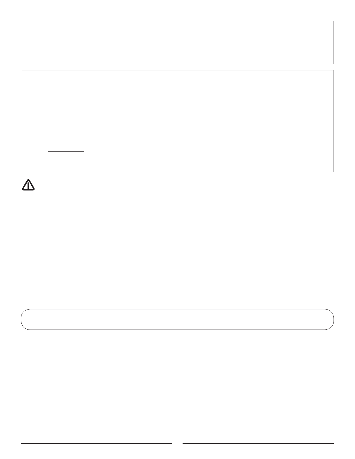
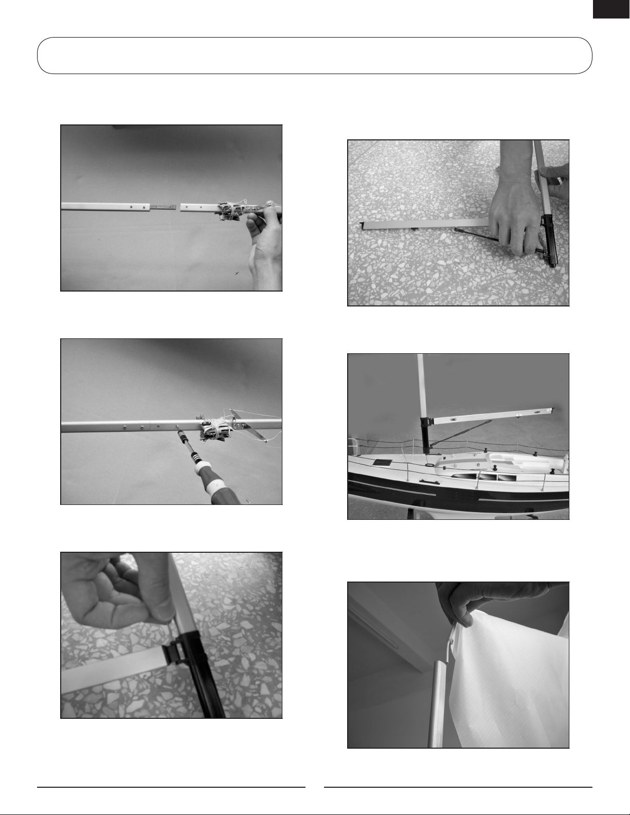
1. Take out the two-piece mast, main sail
boom, boat stand, sails and hardware and
so on. Put the hull on the boat stand.
2. Install the anchor with screws using
screwdriver at the bow of the boat.
4. Locate the stern railing and insert it
into the railing stands.
5. Put the railing into the railing stand.
3. Locate the front railing and insert it
into the railing stands.
6. Insert the line into the hole of the
railing.
4
Page 5
EN
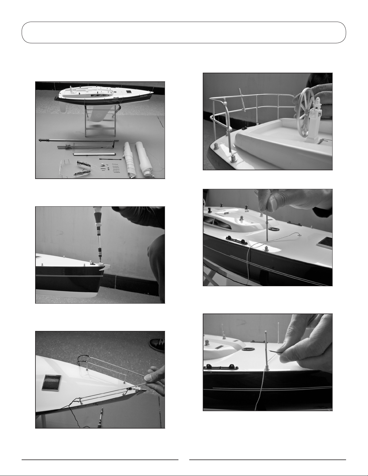
7. Tie a knot with a line to fix the railing
line and cut off the excess lines.
8. Repeat step 6 and 7 to finish all the
railings and railing line installation.
10. Apply a drop or two of thin CA to
each of the points where the railing fits
into the railing stands on the hull.
11. Apply a drop or two of thin CA to
each of the points where the stern railing
fits into the railing stands on the hull.
9. Apply a drop or two of thin CA to each
of the points where the front railing fits
into the railing stands on the hull.
12. Apply a drop or two of thin CA to
each of the knots of the line to prevent
the knots from coming loose.
5
Page 6
EN
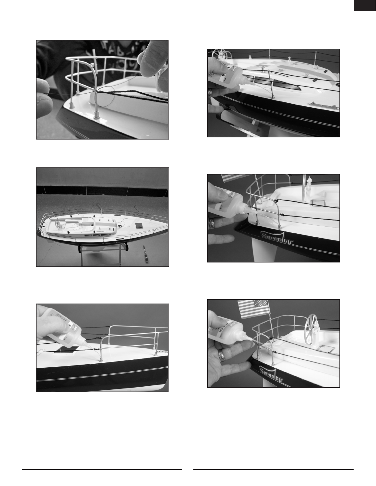
13. Guide the long antenna wire through
the mounts on the stern railing. Slide the
flag mast over the antenna.
Installing the Ballast
14. The flag mast is then inserted through
the mounts and into the hull. Gently
guide the antenna through and out the
top of the flag mast.
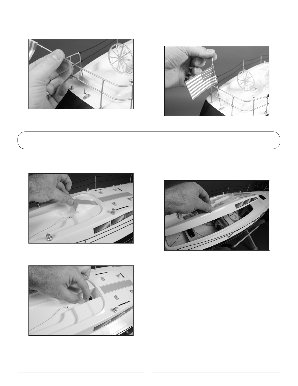
1. Remove the cover from the hull. The
cover is held in position using magnets.
2. Remove the nylon bolt that secures the
hatch cover to the hull.
3. Set the hatch cover aside. The cover
cannot be fully removed as the line to the
sail passes through the hatch cover.
Note: The railing is fragile. Take
care when removing the hatch and
transporting the sailboat.
4. Pour the supplied ballast weight into
the hull and into the keel of the boat. Use
30-minute epoxy to secure the weights
in the keel. Use enough epoxy to cover
the weights so they don't dislodge while
operating the boat.
Hint: You can also use household paint
to secure the weights in the keel. Pour
enough paint into the keel to cover the
weights and allow it to dry overnight.
6
Page 7
Sail Installation
EN
1. Slide the upper and lower mast halves
together.
2. Join the two halves using four 2mm x
4mm screws.
4. Install the adjust support which
connects the main mast and main sail
boom.
5. Slide the mast assembly into the fitting
on the top of the hull.
3. Locate the main sail boom and connect
it to the main mast with a screw and nut.
6. Remove the masthead crane and slide
the unrolled main sail to the bottom of
the mast.
7
Page 8

EN
7. Mount the masthead crane to the top
of the mast.
8. Please note the letter mark on the
rolled lines.
10. Open the rigging clip and attach it to
the eye plate where the marked letter is
the same as the letter on the according
rigging, such as “C” to “C” as shown in
the picture.
11. Pull up carefully on the jib stay to
adjust the tension of the lines.
9. Please note the same letter mark with
the lines on the deck.
8
Page 9

EN
12. Pass the rigging line of the jib sail
through the eye plate on the mast and
then thread the line into the jib stay.
Thread the line through the swivel and tie
an overhand knot to the jib stay to secure.
Connect “I” to “I” as shown in the picture.
14. Pass the rigging line of the main sail
through the hole of the masthead crane,
thread the line through a jib stay and at
last thread the line through the swivel,
ending with tying a knot. Connect “J” to
“J” as shown in the picture.
13. Thread the rigging lines of the top of
the jib sail through the eye plate on the
mast, round it on the cleat and secure
it by tying a knot. Connect “K” to “K” as
shown in the picture.
15. The finished installation of the rigging
lines of the main sail.
9
Page 10

EN
16. Pull up the jib stay on the jib boom to
adjust the tension of the lines.
17. Pull up the jib stay of the main boom
to adjust the tension of the lines.
18. The sailboat with installation finished.
Note: Keep the main and jib boom lines
loose until the radio is operational for
adjustment.
Note: Adjust the lines so the mast is
centered and perpendicular to the hull.
10
Page 11

EN
D
J
Rigging Guide
H
J
J
K
I
K
E
C
D
C
M
G
N
H
F
K
H
E
F
C
D
11
G
Page 12

EN
Charging the Receiver Battery
1. Use a charger (we recommend the
SPM9526 Spektrum 150mA wall charger)
to charge the receiver battery. Allow
10–12 hours to fully charge the receiver
battery when it is fully discharged.
2. Once the receiver battery is charged,
place it in the boat.
3. Check the switch harness to make sure
it is in the OFF position. Plug the receiver
battery into the switch harness. Make
sure to match the polarity of the plugs so
the black and red wires align with each
other.
4. Replace the hatch cover.
12
Page 13

Transmitter Battery Installation and Checking the Controls
EN
1. Slide the battery cover off in the
directions shown to access the battery
compartment.
2. Install four AA-size batteries in the
transmitter. Make sure to match the
polarity of the batteries to the polarity
molded into the battery compartment
of the radio. Slide the cover back into
position on the radio.
4. Move the stick on the transmitter to
the right. The rear edge of the rudder
will move to the right as shown. Actuate
the STR (steering) reversing switch if the
direction is reversed.
3. Slide the power switch on the
transmitter to the ON position. Move the
receiver switch to the ON position.
Rear Edge
Note: If you find the boat is turning too
quickly, you can reduce the amount of
rudder by adjusting the dual rate knob on
the top of the transmitter.
13
Page 14

EN
5. With the radio system on, move the
left stick on your transmitter "up" and
manually push the main sail and jib sail
open. You should be able to open the
sails to at least a 60-degree angle. If
you cannot do this, it will be necessary
to adjust the length of the line (allowing
more slack) by adjusting the jib stays
located underneath the main sail and jib
sail booms.
6. Move the left stick of your transmitter
"down" to close the sails. The sails should
close, with the jib sail being tighter than
the main sail. There should be some
slack left in the sail rigging when the sail
gimbal moves the sails in.
14
Page 15

Sailing Tips
After you have finished rigging the sails, it will be helpful to adjust the sails in order to optimize
the performance of your boat. It is often necessary to briefly sail the Serenity in order to see
how the sails need to be trimmed. Take your time to optimize your sailing pleasure.
1. Check to make sure the main boom
and jib boom are in line with each other.
Adjust the jib stay at the top of the jib
sail to position the jib boom.
EN
The following will help you get started in sailing. Follow the instructions and understand it takes
some practice to become an accomplished yachtsman.
Do not sail if the winds are too strong. Best results will occur with winds between 5 and 12 mph.
WIND
Starboard Tack
Close-Hauled
NO SAIL ZONE
45° 45°
Wind Abeam
Starboard
Tack
Quarter Lee
Port Tack
Port
Tack
Close-Hauled
Wind Abeam
Quarter Lee
Running
15
Page 16

EN
Quarter Lee
Sails: Letting both out a little
Rudder: To the left
Starboard Tack—Running
Sails: Letting both out to
their maximum position
Rudder: In center position
Port Tack—Running
Sails: Letting both out to
their maximum position
Rudder: In center position
Quarter Lee
Sails: Pulling both in a little
Rudder: In center position
Luffing Up
Sails: Pulling in bit by bit
Rudder: To the left
more
WIND
Wind Abeam
Sails: Each at a position of 45°
Rudder: In center position
STARBOARD TACK
Port Tack—Close-Hauled
Sails: Keeping pulled in
Rudder: To be held at the
center as long as the
sails do not shiver
Tacking
Sails: Keeping pulled in
Rudder: To the left
PORT TACK
START
Bearing Away
Sails: Let both out so as not to
Rudder: To the left
Starboard Tack—Close-Hauled
Sails: Keeping pulled in
Rudder: To be held at the center
45°
Port Tack—Close-Hauled
Sails: Keeping pulled in
Rudder: To be held at the
shiver
Tacking
Sails: Keeping
Rudder: To the left
as long as the sails do
not shiver
Tacking
Sails: Keeping
Rudder: To the right
center as long as the
sails do not shiver
pulled in
pulled in
Wind Abeam
Sails: Each at a position of
45°
Rudder: In center position
Sails Control
Luffing Up
Sails: Pulling both in all the
way
Rudder: To the left
Rudder Control
16
Page 17

Warranty and Repair Policy
Warranty Period
Exclusive Warranty- Horizon Hobby, Inc., (Horizon) warranties that the Products purchased (the
“Product”) will be free from defects in materials and workmanship at the date of purchase by the
Purchaser.
Limited Warranty
Horizon reserves the right to change or modify this warranty without notice and disclaims all
other warranties, express or implied.
(a) This warranty is limited to the original Purchaser (“Purchaser”) and is not transferable. REPAIR OR
REPLACEMENT AS PROVIDED UNDER THIS WARRANTY IS THE EXCLUSIVE REMEDY OF THE PURCHASER.
This warranty covers only those Products purchased from an authorized Horizon dealer. Third party
transactions are not covered by this warranty. Proof of purchase is required for all warranty claims.
(b) Limitations- HORIZON MAKES NO WARRANTY OR REPRESENTATION, EXPRESS OR IMPLIED, ABOUT NONINFRINGEMENT, MERCHANTABILITY OR FITNESS FOR A PARTICULAR PURPOSE OF THE PRODUCT. THE PURCHASER
ACKNOWLEDGES THAT THEY ALONE HAVE DETERMINED THAT THE PRODUCT WILL SUITABLY MEET THE
REQUIREMENTS OF THE PURCHASER’S INTENDED USE.
(c) Purchaser Remedy- Horizon’s sole obligation hereunder shall be that Horizon will, at its option, (i)
repair or (ii) replace, any Product determined by Horizon to be defective. In the event of a defect, these
are the Purchaser’s exclusive remedies. Horizon reserves the right to inspect any and all equipment
involved in a warranty claim. Repair or replacement decisions are at the sole discretion of Horizon. This
warranty does not cover cosmetic damage or damage due to acts of God, accident, misuse, abuse,
negligence, commercial use, or modification of or to any part of the Product. This warranty does not
cover damage due to improper installation, operation, maintenance, or attempted repair by anyone
other than Horizon. Return of any Product by Purchaser must be approved in writing by Horizon before
shipment.
Damage Limits
HORIZON SHALL NOT BE LIABLE FOR SPECIAL, INDIRECT OR CONSEQUENTIAL DAMAGES, LOSS OF
PROFITS OR PRODUCTION OR COMMERCIAL LOSS IN ANY WAY CONNECTED WITH THE PRODUCT,
WHETHER SUCH CLAIM IS BASED IN CONTRACT, WARRANTY, NEGLIGENCE, OR STRICT LIABILITY.
Further, in no event shall the liability of Horizon exceed the individual price of the Product on which
liability is asserted. As Horizon has no control over use, setup, final assembly, modification or misuse,
no liability shall be assumed nor accepted for any resulting damage or injury. By the act of use, setup or
assembly, the user accepts all resulting liability.
If you as the Purchaser or user are not prepared to accept the liability associated with the use of this
Product, you are advised to return this Product immediately in new and unused condition to the place of
purchase.
Law: These Terms are governed by Illinois law (without regard to conflict of law principals).
Warranty Services
Questions, Assistance, and Repairs
Your local hobby store and/or place of purchase cannot provide warranty support or repair. Once
assembly, setup or use of the Product has been started, you must contact Horizon directly. This will
enable Horizon to better answer your questions and service you in the event that you may need any
assistance. For questions or assistance, please direct your email to productsupport@horizonhobby.com, or
call 877.504.0233 toll free to speak to a Product Support representative. You may also find information
on our website at www.horizonhobby.com.
Inspection or Repairs
If this Product needs to be inspected or repaired, please use the Horizon Online Repair Request
submission process found on our website or call Horizon to obtain a Return Merchandise Authorization
(RMA) number. Pack the Product securely using a shipping carton. Please note that original boxes may be
included, but are not designed to withstand the rigors of shipping without additional protection. Ship via
a carrier that provides tracking and insurance for lost or damaged parcels, as Horizon is not responsible
17
EN
Page 18

EN
for merchandise until it arrives and is accepted at our facility. An Online Repair Request is available at
www.horizonhobby.com http://www.horizonhobby.com under the Repairs tab. If you do not have internet
access, please contact Horizon Product Support to obtain a RMA number along with instructions for
submitting your product for repair. When calling Horizon, you will be asked to provide your complete
name, street address, email address and phone number where you can be reached during business
hours.
When sending product into Horizon, please include your RMA number, a list of the included items, and
a brief summary of the problem. A copy of your original sales receipt must be included for warranty
consideration. Be sure your name, address, and RMA number are clearly written on the outside of the
shipping carton.
Notice: Do not ship batteries to Horizon. If you have any issue with a battery, please contact
the appropriate Horizon Product Support office.
Warranty Inspection and Repairs
To receive warranty service, you must include your original sales receipt verifying the proof-ofpurchase date. Provided warranty conditions have been met, your Product will be repaired or replaced
free of charge. Repair or replacement decisions are at the sole discretion of Horizon.
Non-Warranty Repairs
Should your repair not be covered by warranty the repair will be completed and payment will
be required without notication or estimate of the expense unless the expense exceeds 50%
of the retail purchase cost. By submitting the item for repair you are agreeing to payment of the
repair without notication. Repair estimates are available upon request. You must include this request
with your repair. Non-warranty repair estimates will be billed a minimum of ½ hour of labor. In addition
you will be billed for return freight. Horizon accepts money orders and cashiers checks, as well as Visa,
MasterCard, American Express, and Discover cards. By submitting any item to Horizon for inspection or
repair, you are agreeing to Horizon’s Terms and Conditions found on our website under the Repairs tab.
Warranty and Service Contact Information
Country of Purchase Horizon Hobby Address Phone Number/Email Address
Horizon Service Center
United States of
America
United Kingdom Horizon Hobby Limited
Germany
France Horizon Hobby SAS
(Electronics and engines)
Horizon Product Support
(All other products)
Horizon Technischer
Service
4105 Fieldstone Rd
Champaign, Illinois
61822 USA
4105 Fieldstone Rd
Champaign, Illinois
61822 USA
Units 1-4 Ployters Rd
Staple Tye
Harlow, Essex
CM18 7NS
United Kingdom
Hamburger Str. 10
25335 Elmshorn
Germany
14 Rue Gustave Eiffel
Zone d’Activité du Réveil Matin
91230 Montgeron
877-504-0233
Online Repair Request visit:
www.horizonhobby.com/repairs
877-504-0233
productsupport@horizonhobby.com
+44 (0) 1279 641 097
sales@horizonhobby.co.uk
+49 4121 46199 66
service@horizonhobby.de
+33 (0) 1 60 47 44 70
infofrance@horizonhobby.com
Customer Service Information
Country of Purchase Horizon Hobby Address Phone Number/Email Address
United States Sales
United Kingdom Horizon Hobby Limited
Germany Horizon Hobby GmbH
France Horizon Hobby SAS
4105 Fieldstone Rd
Champaign, Illinois
61822 USA
Units 1-4 Ployters Rd
Staple Tye
Harlow, Essex
CM18 7NS
United Kingdom
Hamburger Str. 10
25335 Elmshorn
Germany
14 Rue Gustave Eiffel
Zone d’Activité du Réveil Matin
91230 Montgeron
(800) 338-4639
sales@horizonhobby.com
+44 (0) 1279 641 097
sales@horizonhobby.co.uk
+49 4121 46199 60
service@horizonhobby.de
+33 (0) 1 60 47 44 70
infofrance@horizonhobby.com
18
Page 19

Regulatory Information
EN
AT
DK
HU
LV
RO SI
BG
ES
IE
MT
SE
CY
FI
IT
NL
CZ
FR
LT
PL
SK
DE
GR
LU
PT
UK
Compliance Information for the European Union
Declaration of Conformity
(in accordance with ISO/IEC 17050-1)
No. HH2011030701
Declaration of Conformity
(in accordance with ISO/IEC 17050-1)
No. HH2011030701
Product(s): PRB Serenity 1 Meter Sailboat RTR
Item Number(s): PRB3450
Equipment class: 2
The object of declaration described above is in conformity with the requirements of the specifications listed below,
following the provisions of the European R&TTE directive 1999/5/EC:
EN 300-328 V1.7.1
EN 301 489-1 V1.7.1: 2006
EN 301 489-17 V1.3.2: 2008
EN 60950-1:2006+A11
Signed for and on behalf of:
Horizon Hobby, Inc.
Champaign, IL USA
March 7, 2011
Steven A. Hall
Vice President
International Operations and Risk Management
Horizon Hobby, Inc.
19
Page 20

EN
Instructions for Disposal of WEEE by Users in the European Union
This product must not be disposed of with other waste. Instead, it is the user’s responsibility
to dispose of their waste equipment by handing it over to a designated collection point for the
recycling of waste electrical and electronic equipment. The separate collection and recycling of
your waste equipment at the time of disposal will help to conserve natural resources and ensure that it is recycled in a manner that protects human health and the environment. For more
information about where you can drop off your waste equipment for recycling, please contact your local
city ofce, your household waste disposal service or where you purchased the product.
FCC Information
This device complies with part 15 of the FCC rules. Operation is subject to the following two conditions: (1) This
device may not cause harmful interference, and (2) this device must accept any interference received, including
interference that may cause undesired operation. Caution: Changes or modifications not expressly approved by the
party responsible for compliance could void the user’s authority to operate the equipment. This product contains
a radio transmitter with wireless technology which has been tested and found to be compliant with the applicable
regulations governing a radio transmitter in the 2.400GHz to 2.4835GHz frequency range.
Antenna Separation Distance
When operating your transmitter, please be sure to maintain a separation distance of at least 5 cm between your
body (excluding fingers, hands, wrists, ankles and feet) and the antenna to meet RF exposure safety requirements
as determined by FCC regulations.
The illustrations below show the approximate 5 cm RF exposure area and typical hand placement when operating
your transmitter.
PRB3451 Hull
PRB3452 Switch Cover and Nut
PRB3453 Capstan (4 pc)
PRB3454 Pulley Sets
PRB3455 Railing Stand (16 pc)
PRB3456 Jack Stays (4 pc)
PRB3457 Steering Wheel Set
PRB3458 Rudder with Arm
PRB3459 Anchor
PRB3460 Balloon with Strap
PRB3461 Rigging Line
PRB3462 Railing Line
PRB3463 Winch Retaining Ring
PRB3464 Ballast
PRB3465 Hatch
PRB3466 Railing Post (6 pc)
Replacement Parts
PRB3467 Railing (Front)
PRB3468 Railing (Rear)
PRB3469 Mast
PRB3470 Boom (Front and Rear)
PRB3471 Boom Turnbuckle
PRB3472 Spreader
PRB3473 Jib Stay (7 pc)
PRB3474 Snaps (10 pc)
PRB3475 Main Sail
PRB3476 Jib Sail
PRB3477 Boat Stand
PRB3478 4.8V Ni-MH Battery
PRB3479 Switch Harness
PRB3480 Sail Winch Servo
SPMMR200 Receiver
SPMR2200 Transmitter
20
Page 21

®
© 2011 Horizon Hobby, Inc.
horizonhobby.com
www.proboatmodels.com
The Spektrum trademark is used with permission of Bachmann Industries, Inc.
All other marks are trademarks or registered trademarks of
Horizon Hobby, Inc
US 7,391,320. Other patents pending.
31120Printed 03/2011
 Loading...