

Page 1

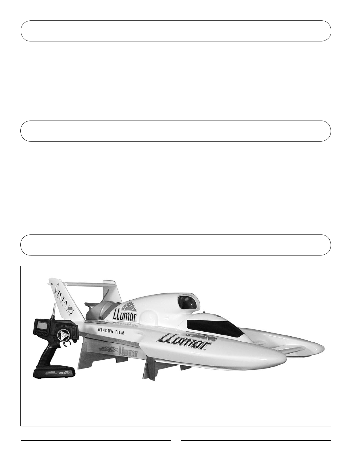
1/8-Scale Miss LLumar Unlimited Hydroplane
Owner's Manual
Specifications
Length .......................................................................................45.25 in (1131.3mm)
Beam ........................................................................................... 23.75 in (593.8mm)
Engine ............................................................. Zenoah® G26M and Tuned Exhaust
Speed .............................................................................................................+35 MPH
®
Radio System ........................................................................ JR
Propeller .................................................................................................. Prather 270
XR3i FM 75MHz
Page 2

Introduction
Congratulations on the purchase of your
Pro Boat
™ Miss LLumar. This is a 1/8-scale replica
of the world famous full-scale hydro. You are just
minutes from one of the most thrilling experiences
the radio control hobby has to offer.
The Pro Boat Miss LLumar is a professionally built,
ready-to-run fiberglass model.
®
Powered by the potent Zenoah
G26M engine, you
will be able to race across the water at speeds in
It is very important that you operate this boat
responsibly. With proper care and maintenance, you
will be able to enjoy your Miss LLumar for many
years to come.
Carefully unpack your Miss LLumar and examine
the boat and its contents. The box should contain
the Miss LLumar RTR with radio installed, a boat
®
stand, and the JR
XR3i radio transmitter. If you are
missing any of these items or notice any damage,
immediately contact the place of purchase.
excess of 35 mph!
Table of Contents
Limited Warranty & Limits of Liability .................................................................................................................... 3
Additional Required Items .........................................................................................................................................
Suggested Field Equipment and Supplies ................................................................................................................
Contents ........................................................................................................................................................................ 5
Section 1: Building the Boat Stand ...........................................................................................................................
Section 2: Attaching the Turn Fin ..............................................................................................................................
Section 3: Removing the Canopy .............................................................................................................................
Section 4: Installing the Radio System Batteries ...................................................................................................
Section 5: Installing the Rudder ................................................................................................................................
Section 6: Propeller Balancing ...................................................................................................................................
Section 7: Fueling the Tank .......................................................................................................................................
Section 8: Fuel/Oil Mixture ......................................................................................................................................
Section 9: Range Check the XR3i Radio System ...............................................................................................
Section 10: Starting the Engine ...............................................................................................................................
Section 11: Stopping the Engine .............................................................................................................................
Section 12: Initial Launch of the Miss LLumar ....................................................................................................
Section 13: Cooling System .....................................................................................................................................
Section 14: Clutch ......................................................................................................................................................
Section 15: Troubleshooting Guide ........................................................................................................................
Section 16: Hull Care ................................................................................................................................................
Section 17: Maintenance ...........................................................................................................................................
Section 18: Replacement Parts ...............................................................................................................................
Appendix ......................................................................................................................................................................18
10
10
10
11
12
12
13
14
15
15
15
17
5
5
6
6
7
7
9
9
22
Page 3

Limited Warranty & Limits of Liability
Pursuant to this Limited Warranty, Horizon Hobby,
Inc. will, at its option, (i) repair or (ii) replace, any
product determined by Horizon Hobby, Inc. to be
defective. In the event of a defect, these are
your exclusive remedies.
This warranty does not cover cosmetic damage
or damage due to acts of God, accident, misuse,
abuse, negligence, commercial use, or modification
of, or to any part of the Product. This warranty
does not cover damage due to improper installation,
operation, maintenance, or attempted repair by
anyone other than an authorized Horizon Hobby,
Inc. service center. This warranty is limited to the
original purchaser and is not transferable. In no case
shall Horizon Hobby’s liability exceed the original
cost of the purchased product and will not cover
consequential, incidental or collateral damage.
Horizon Hobby, Inc. reserves the right to inspect
any and all equipment involved in a warranty claim.
Repair or replacement decisions are at the sole
discretion of Horizon Hobby, Inc. Further, Horizon
Hobby reserves the right to change or modify this
warranty without notice.
REPAIR OR REPLACEMENT AS PROVIDED
UNDER THIS WARRANTY IS THE EXCLUSIVE
REMEDY OF THE CONSUMER. HORIZON
HOBBY, INC. SHALL NOT BE LIABLE FOR ANY
INCIDENTAL OR CONSEQUENTIAL DAMAGES.
As Horizon Hobby, Inc. has no control over
use, setup, final assembly, modification or
misuse, no liability shall be assumed nor
accepted for any resulting damage or injury.
By the act of use, setup or assembly, the user
accepts all resulting liability.
If you as the purchaser or user are not
prepared to accept the liability associated
with the use of this product, you are advised
to return this product immediately in
new and unused condition to the place of
purchase.
Safety Precautions
This is a sophisticated hobby product and not a
toy. It must be operated with caution and common
sense and requires some basic mechanical ability.
Failure to operate this product in a safe and
responsible manner could result in injury or damage
to the product or other property. This product
is not intended for use by children without
direct adult supervision.
The product manual contains instructions
for safety, operation and maintenance.
It is essential to read and follow all the
instructions and warnings in the manual,
prior to assembly, setup or use, in order to
operate correctly and avoid damage or injury.
Questions, Assistance, and Repairs
Your local hobby store and/or place of purchase
cannot provide warranty support or repair. Once
assembly, setup or use of the product has been
started, you must contact Horizon Hobby, Inc.
directly. This will enable Horizon to better answer
your questions and service you in the event that
you may need any assistance.
Questions or Assistance
For questions or assistance, please direct your
email to productsupport@horizonhobby.com, or
call 877.504.0233 toll free to speak to a service
technician.
Inspection or Repairs
If your product needs to be inspected or repaired,
please call for a Return Merchandise Authorization
(RMA). Pack the product securely using a shipping
carton. Please note that original boxes may be
included, but are not designed to withstand the
rigors of shipping without additional protection. Ship
via a carrier that provides tracking and insurance for
3
Page 4

Limited Warranty & Limits of Liability (cont)
lost or damaged parcels, as Horizon Hobby, Inc. is
not responsible for merchandise until it arrives and
is accepted at our facility. Include your complete
name, address, phone number where you can be
reached during business days, RMA number, and a
brief summary of the problem. Be sure your name,
address, and RMA number are clearly written on
the shipping carton.
Warranty Inspection and Repairs
To receive warranty service, you must include your
original sales receipt verifying the proof-of-purchase
date. Providing warranty conditions have been met,
your product will be repaired or replaced free of
charge. Repair or replacement decisions are at the
sole discretion of Horizon Hobby.
Non-Warranty Repairs
Should your repair not be covered by warranty and
the expense exceeds 50% of the retail purchase
cost, you will be provided with an estimate advising
you of your options. You will be billed for any
return freight for non-warranty repairs. Please
advise us of your preferred method of payment.
Horizon Hobby accepts money orders and cashiers
checks, as well as Visa, MasterCard, American
Express, and Discover cards. If you choose to pay
by credit card, please include your credit card
number and expiration date. Any repair left unpaid
or unclaimed after 90 days will be considered
abandoned and will be disposed of accordingly.
Electronics and engines requiring inspection
or repair should be shipped to the following
address (freight prepaid):
Horizon Service Center
4105 Fieldstone Road
Champaign, Illinois 61822
All other products requiring inspection or
repair should be shipped to the following
address (freight prepaid):
Limited Warranty Period
Horizon Hobby, Inc. guarantees Pro Boat™
products to be free from defects in both material
and workmanship at the date of purchase.
General Guidelines
It is important that you read and follow this
®
instruction manual, along with the JR
system manual and the Zenoah
manual, before you run this exciting boat. Failure
to read and understand the manual could result
is personal injury, property damage or permanent
damage to your boat! It is also important to run
your boat responsibly. With proper care and
maintenance, you will be able to proudly enjoy your
Miss LLumar for many years to come.
This boat has been designed to race in an oval path,
just like its full scale counterpart. At high speeds
do not attempt turns to the left, as the boat may
become unstable. If you have to turn left, do so in a
large diameter turn and at slow speeds.
When operating the boat, stay clear of people,
full-scale boats, stationary objects and wildlife. It is
preferable to operate the Miss LLumar in low wake,
low wind conditions and in areas free of people,
wildlife and objects.
Before you operate your model, make sure that
your frequency is clear. If someone is operating on
the same frequency, both models could go out of
control, possibly causing damage to the models or
to others. Check all of the hardware, manifold, pipe
and propeller for security before and after each run.
If at any time while operating your model you
sense any abnormal function, end your operation
immediately. Do not operate your boat again until
you are certain the problem has been corrected.
Always stay clear of the propeller
®
XR3i radio
G26 engine
.
Horizon Product Support
4105 Fieldstone Road
Champaign, Illinois 61822
44
Page 5
Additional Required Items
Although the Miss LLumar comes fully assembled and ready for action, you will need a few additional items
in order to run your boat. You will need the following:
Zenoah® 2-Cycle Oil (ZEN20001)
CA or epoxy glue
Flex Shaft lubrication (see local hobby store)
Fuel container
Fuel Pump (HAN155)
12 “AA” alkaline batteries (8 for the transmitter
and 4 for the receiver)
Gasoline (+87 Octane), ethanol-free
Suggested Field Equipment and Supplies
In addition to the items needed to run the Miss LLumar, we recommend that you carry the following
in your field box:
Engine Tuning Screwdriver (DYN2775)
Clean towels
Extra Propellers (PRAB270)
2mm hex wrench
2.5mm hex wrench
4mm hex wrench
#1 Phillips
Small crescent wrench
Wax
Screw-locking compound
Contents
• Assembled 1/8 scale Miss LLumar RTR
®
XR3i radio transmitter
• JR
• Boat stand
• Rudder
5
Page 6
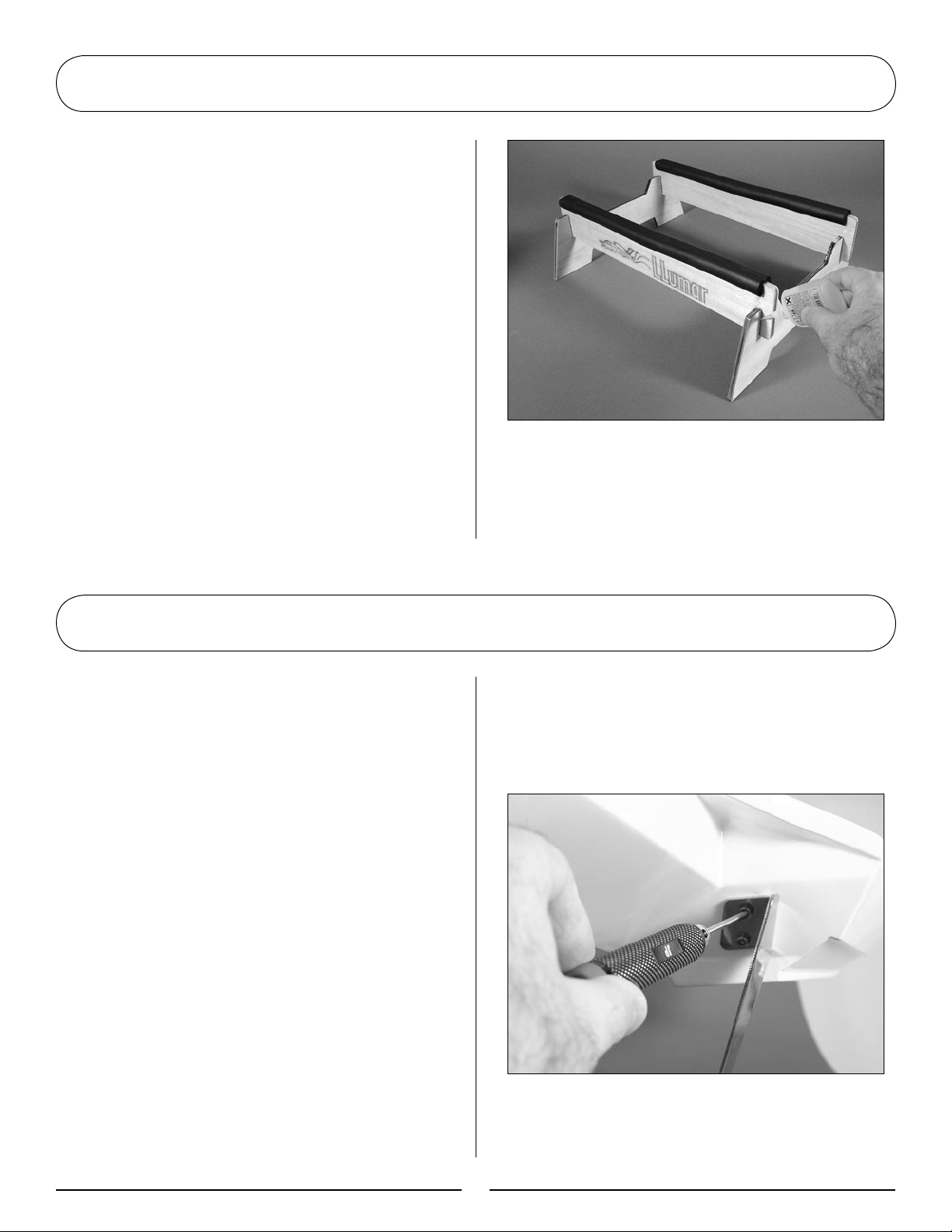
Section 1: Building the Boat Stand
Parts Required
Plywood boat stand pieces (4)
Tools and Adhesives Needed
CA or epoxy
1. Attach the side boat pieces by interlocking
them into the end pieces as shown.
2. Secure the interlocking boat stand with
medium thick CA or epoxy. Make certain you
allow the CA or epoxy to fully cure before
placing the boat on the stand.
Section 2: Attaching the Turn Fin
Parts Required
Turn Fin
3mm hex screws (2)
Tools and Adhesives Needed
3mm hex driver
Blue Threadlock
1. Locate the included turn fin. This will be
attached to the right sponson. Any attempt to
turn the boat left may cause the boat to flip,
especially if this is done in a tight diameter and
at high speeds.
2. Place the Miss LLumar on the completed boat
stand once the glue has fully cured.
3. Locate the turn fin and the included 3mm
hex screws (2) to secure the turn fin.
4. Carefully place a few drops of blue Threadlock
on the threads of all four hex screws. This will
help to keep the screws secured to the blind
nuts within the sponson.
5. Carefully attach the turn fin onto the right
sponson as shown and tighten the hex screws
with a 3mm hex driver.
6
Page 7

Section 3: Removing the Canopy
Unscrew the 2 knurled hatch-mounting screws from
the rear of the hatch. Lift the hatch from the boat.
Section 4: Installing the Radio System Batteries
Tools and Accessories Required
12 "AA" batteries
2.5mm hex wrench
Receiver Batteries
1. Remove the 2.5mm hex head screws that
secure the clear Lexan radio box cover.
3. Wrap the battery holder in the foam
provided. Secure the foam using a rubber
band. Reinstall the battery holder into the
radio compartment.
2. Remove the receiver battery holder and install
4 “AA” alkaline batteries in the battery holder.
Note proper polarity.
7
Page 8

Section 4: Installing the Radio System Batteries (cont)
4. Plug the switch harness into both the receiver
and the battery box following the instructions
provided with the radio. Secure the radio box
cover with the hex head screws.
Transmitter Batteries
1. Remove the transmitter from the box.
2. Remove the battery cover on the bottom
of the transmitter.
4. Insert the battery holder in the transmitter
following the directions provided with the
radio system.
5. Install the battery cover back into position on
the bottom of the transmitter.
6. Turn on the transmitter and confirm that the
LCD illuminates, indicating proper installation of
fully charged batteries.
3. Insert 8 “AA” alkaline batteries into the
battery holder. Note proper polarity.
7. Turn on the receiver switch and move the
controls. Confirm that all controls operate in
the proper direction and are controlled by the
proper transmitter input.
8. Turn the transmitter and the receiver switch
off. To keep the boat from receiving stray
signals, the transmitter should be turned on first,
followed by the receiver. Likewise, the receiver
should be turned off first, then the transmitter.
Note: Remember the transmitter
must be sending a signal the entire
time the receiver is on.
8
Page 9

Section 5: Installing the Rudder
Parts Required
Rudder
2.5mm hex screw
Tools and Adhesives Required
2.5mm hex driver
1. Locate the stainless steel rudder and
2.5mm hex screw.
3. Find the flat spot on the rudder. Using the
2.5mm hex screw, tighten the hex screw on the
flat spot as shown.
2. Carefully insert the rudder as shown.
Section 6: Propeller Balancing
For optimum performance, propeller balancing can
add several mph to top speed and reduce vibration.
There are several different propeller balancing tools
available. Read the instructions that accompany
the propeller balancing tool regarding removing
material from the propeller. Removing material from
the correct part of the propeller is crucial to the
performance of the propeller. Contact a local hobby
retail store for assistance.
9
Page 10

Section 7: Fueling the Tank
Use only Zenoah® 2-Cycle Synthetic Oil and
gasoline mixed 32:1 to power the Miss LLumar.
Keep the fuel in a moisture-free environment,
as stale fuel will cause the Zenoah G26M engine to
lose performance.
Section 8: Fuel/Oil Mixture
Parts Needed
Unleaded gasoline
Zenoah® 2-stroke oil
Section 9: Range Check the XR3i Radio System
Important
Range check your radio system before the first run
of the Miss LLumar to make certain it is functioning
correctly. Make sure that the receiver antenna is
extended properly.
1. With the boat in its stand, the radio system
turned on and the transmitter antenna down,
walk off 30 paces (90 feet) from the Pro Boat
Miss LLumar.
2. Have an assistant remain with the boat
to check for proper control movement
from your transmitter input. When you are
satisfied that the radio is functioning properly,
you can continue.
™
1. Mix gasoline and 2-stroke oil (ZEN20001) at a
mixing ratio of 32:1 (gas to oil).
2. Remove the fuel tank cap and fill the fuel tank
with the gasoline and oil mixture. Use a funnel
to prevent spills. If you do spill, be certain to
immediately wipe it up with a clean towel.
Note: Always perform a range
check prior to operating your boat
after any major repair, installation of
new batteries or at the beginning of
each boating session.
3. With your assistant again 90 feet away, re-
start the engine. Quickly repeat the same range
check as above, carefully making sure you
observe proper control movement from your
transmitter input. Make certain you complete
this within 60 seconds to prevent the engine
from overheating. Push the kill switch to stop
the engine. Once you are satisfied your radio
system has passed the range check, you are
ready to start the engine and launch your boat.
10
Page 11

Section 10: Starting the Engine
Note: The Zenoah® G26M
carburetor is factory adjusted to
deliver optimum performance. See
the Zenoah Engine manual for
fine-tuning adjustments and other
helpful information to make your
RC boating experience trouble-free.
Priming the Engine
Pull-starting the Engine
With an assistant holding the boat to the boat
stand and bracing the engine with one hand, pull
the starting cord briskly several times. Once the
engine fires (begins to start), open the choke.
Prolonged choking will flood the engine with fuel.
See Section 15: Troubleshooting Guide to correct
the flooding condition.
Press the priming bulb several times until it becomes
filled with fuel. This is not necessary if the engine
has recently been run.
Choking the Engine
Close the choke by rotating the small yellow
tubing extension. This is not necessary if the
engine is warm.
Note: The engine is water-cooled.
Refrain from running the engine
without proper cooling water or
engine damage will result. Carefully
place the boat in the water as soon
as possible after the engine has
been started.
11
Page 12

Section 11: Stopping the Engine
Idle the boat near shore and press the kill switch
located on top of the cockpit as shown.
Section 12: Initial Launch of the Miss LLumar
With the transmitter antenna up, maneuver the Miss
LLumar in an oval, turning only to the right at slow
to medium speeds. Make certain that the boat and
radio system are functioning correctly.
As you are running the Miss LLumar in an oval,
watch for water being discharged from the water
outlet on the left side of the hull. Water flowing
from the water outlet indicates the engine is
being properly cooled. If you do not notice any
water coming from the water outlet, bring the
boat in and make sure that the water cooling line
or the brass water pickup located near the rudder
are not clogged.
If at anytime you notice the boat and/or radio
system are not functioning correctly, end the
operation of the boat immediately and do not run
the boat again until you are confident the problems
have been corrected.
12
Page 13

Section 13: Cooling System
Zenoah® G26M Engine
Carburetor
Mounting Plat
e
Wa
ter-Cooled
Cy
linder Head
Tuned Pipe
Tuned Pipe Fitting
Wa
ter Pump
Rudder
Pick-U
p
T
ube
Rudder
Pick-Up
T
ube
Wate
r
Outlet
Wate
r
Outlet
Water Pump
The water pump is operated from crankcase
pressure. Be sure that water is exiting the 2 water
jackets mounted on the left side of the boat when
the engine is running and the boat is in the water. If
water does not stream out of either the exhaust or
cylinder head cooling ports, immediately stop engine
operation and remove obstructions in the lines or
replace broken cooling lines.
Hint: To test each cooling line
for obstructions or a leak in the
cooling system, place a piece of
tubing over the water inlet tubes
in front of the rudder and blow
into the tube. When testing for
obstructions in the cooling system,
be sure to isolate each system by
pinching the appropriate water lines.
Water-Cooled Cylinder Head and Exhaust
Manifold Cooling Jacket
The exhaust system is cooled independently from
the cylinder head. See line drawings for proper
cooling line routing. Do not alter the cooling line
routing method.
13
Page 14

Section 14: Clutch
The centrifugal clutch automatically engages when
the engine rpm is increased. Be sure that the idle
speed adjustment is set low enough so that the
propeller does not rotate at idle.
Periodically disassemble the clutch and clean debris
from the clutch shoes and the inner clutch bell with
DYN5505 Dynamite® Nitro Force.
14
Page 15

Section 15: Troubleshooting Guide
Problem Possible Solution
Engine will not start Improper needle setting: See Zenoah® Engine Manual
Out of fuel: Fill fuel tank
Improper fuel: Use fresh Gasoline & Zenoah 2-Cycle Oil (mixed 32 parts gas to 1 part oil)
Bad spark plug: Replace spark plug
Flooded engine: Remove spark plug, invert boat and operate the pull-starter to
remove fuel
Engine starts, then dies Fuel line blocked or broken: Connect or replace fuel line
Reset needles to baseline setting: See Zenoah instructions
Baseline settings for low-speed and hi-speed needle valves is 1–1
1
/4 turns out
Engine starts and runs for Bad fuel: Replace
several minutes, then dies Improper needle settings: See Zenoah Engine manual
Overheated engine: Check for clogged or damaged cooling system
Debris in carburetor: Remove, clean and replace
Section 16: Hull Care
The hull of the Miss LLumar is finished using the highest quality paints and the most advanced painting
methods available. The base coat/clear cote technique delivers an amazing shine that is as durable as
it is beautiful. To keep your Miss LLumar looking new, you should apply a wax coating as used on
automotive finishes to prevent oxidation and to further protect against damage caused by fuel and other
harmful chemicals.
Section 17: Maintenance
The Pro Boat™ Miss LLumar should provide many
hours of exciting high-speed racing fun with just
minor maintenance. Preventative maintenance is
very important. Taking the time to make sure all
of the screws and bolts are properly secured before
each run and after each operation and regularly
lubricating the flex cable will prevent
many problems.
Replacement parts are available from Pro Boat. See
the back of this manual for specific descriptions and
item numbers.
Items Required
2mm hex wrench
Waterproof grease
Threadlocking compound
It is vitally important to properly lubricate the flex
drive shaft and the propeller shaft with heavy cable
grease every 5–10 hours of operation. You will
also find that it will eventually become necessary
to replace the Teflon liner sleeve of the drive shaft.
At some point, it may also become necessary to
replace the drive shaft (flex cable) as well.
15
Page 16

Section 17: Maintenance (cont)
Simply follow the instructions below to properly
lubricate your drive shaft.
1. Carefully note how the entire drive shaft is
installed. This is pivotal in order to properly
re-assemble the drive shaft after you have
finished lubricating it.
4. Lubricate the entire flex cable with
waterproof grease as shown and then re-install
the flex cable back through the liner and stuffing
box and into the clutch.
2. Loosen and remove the two 2.0mm set
screws that secure the propeller shaft to the
brass ferrule. Remove the prop drive dog and
nylon washer.
3. Remove the drive shaft flex cable. Replace the
Teflon liner as needed.
5. Reassembly in reverse order. Make sure that
the set screws are tightened down on the flat
spots of the prop shaft. Also be certain to place
a drop of threadlock on each set screw before
re-tightening them.
16
Page 17

Section 18: Replacement Parts
Your local hobby store should carry a good supply of Miss LLumar replacement parts. You can also purchase
these parts from Horizon Hobby at
PRB2551 ................................................................................................ Replacement Hull
PRB2552 ................................................................................................ Cockpit
PRB2261 ................................................................................................ Exhaust Cover
PRB2553 ................................................................................................ Horizontal Wing
PRB2255 ................................................................................................ Wing Struts
PRB2554 ................................................................................................ Boat Stand
PRB2297 ................................................................................................ Cooling Tubing
PRB2555 ................................................................................................ Servo Tray set
PRB2264 ................................................................................................ Fuel Tank
PRB2273 ................................................................................................ Kill Switch
PRB2268 ................................................................................................ Throttle Cable with EZ Connector
PRB2556 ................................................................................................ Manifold with Screws
PRB2557 ................................................................................................ Cooling Tubing
PRB2558 ................................................................................................ Fuel Tank
PRB2559 ................................................................................................ Rudder Pushrod Set
PRB2560 ................................................................................................ Servo Pushrod Set
PRB2561 ................................................................................................ Cover for Radio Box
PRB2562 ................................................................................................ Flex Shaft
PRB2266 ................................................................................................ Teflon Liner
PRB2281 ................................................................................................ Prop Drive Dog
PRB2283 ................................................................................................ Prop Strut
PRB2282 ................................................................................................ Prop Shaft
PRB2252 ................................................................................................ Rudder
PRB2254 ................................................................................................ Turn Fin with Hardware
PRB2259 ................................................................................................ Pipe Mount
PRB2563 ................................................................................................ Tuned Pipe
PRB2278 ................................................................................................ Cockpit Nuts (2)
PRB2288 ................................................................................................ Nylon Washers (4)
PRB2564 ................................................................................................ Brass Tube for Water Inlet
PRB2251 ................................................................................................ Rudder Bracket/Arm
PRB2651 ................................................................................................ Water Pump
PRB2565 ................................................................................................ Decal Sheet
PRB2566 ................................................................................................ Instruction Manual
PRB2683 ................................................................................................ Clutch
PRB2686 ................................................................................................ Clutch Shoes
PRB2687 ................................................................................................ Clutch Spring (2)
PRB2688 ................................................................................................ Clutch Bearing
PRAB270 ............................................................................................... Propellor: 2.74x4.2 Bronze
www.horizonhobby.com or call toll-free 1-800-338-4639.
17
Page 18

Appendix
PRB2556
PRB2563
Spark Plug
Carburetor
Pull Start
Primer Button
PRB2558
PRB2273
PRB2563
PRB2651
Carburetor
PRB2254
PRB2275
PRB2283
PRB2252
PRAB270
PRB552
18
PRB2278
Page 19

Notes
19
Page 20

© 2006 Horizon Hobby, Inc.
4105 Fieldstone Road
Champaign, Illinois 61822
(877) 504-0233
www.horizonhobby.com
Printed in China
8551
 Loading...