

Page 1
Specifications
Length................................................................................................................ 36 in (914mm)
Beam.................................................................................................................... 9 in (228mm)
Engine ................................................................ DYN .32 Marine w/Recoil and Tuned Exhaust
Radio System ........................................................................................ JR AM 75MHz Python
Weight ................................................................................................................ 6.5 lb (2.9 kg)
Fuel Tank Capacity .......................................................................................... 12 oz (0.35 liter)
Owner’s Manual
.32 Size Nitro Powered Deep-V Boat
Page 2

WARNING
2
Table of Contents
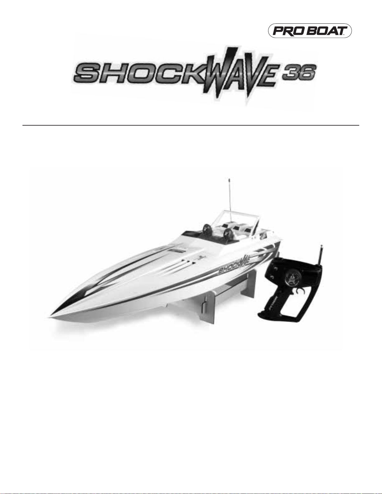
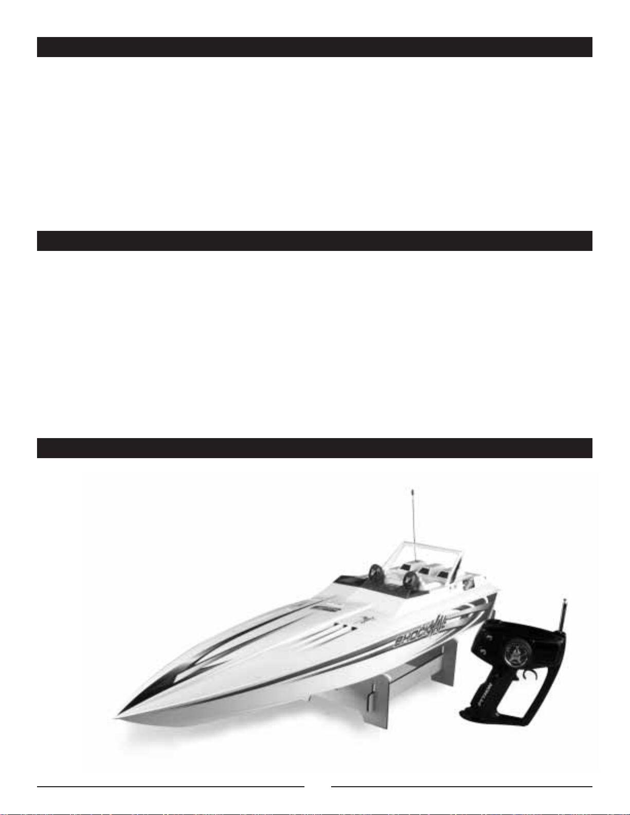
Congratulations on the purchase of your Pro Boat™ShockWave™36
Deep-V. You are just minutes from one of the most thrilling
experiences that the radio control hobby has to offer.
The Pro Boat ShockWave 36 is a professionally built, ready-to-run
Deep-V fiberglass model. Powered by the potent Dynamite
®
.32
marine engine, you will be able to race across the water at scale
speeds in excess of 300mph!
Read this owner’s manual thoroughly. You also need to read the
included Dynamite .32 engine manual, along with the JR
®
Python radio system manual.
It is very important that you operate this boat responsibly. With
proper care and maintenance, you will be able to enjoy your
ShockWave 36 for many years to come.
Carefully unpack ShockWave 36 and examine the boat and its
contents. The box should contain the ShockWave 36 RTR with
radio installed, a boat stand, and the JR Python radio transmitter.
If you are missing any of these items or notice any damage,
immediately contact the place of purchase.
Introduction ...................................................................................................................................................................................................................... 2
Warning ............................................................................................................................................................................................................................ 2
Additional Required Items ................................................................................................................................................................................................ 3
Suggested Field Equipment and Supplies ........................................................................................................................................................................ 3
Contents .......................................................................................................................................................................................................................... 3
Section 1: Installation of Receiver and Transmitter Batteries............................................................................................................................................ 4
Section 2: Rudder Installation .......................................................................................................................................................................................... 5
Section 3: Filling the Fuel Tank ........................................................................................................................................................................................ 5
Section 4: Range Checking the JR Python Radio System..................................................................................................................................................5
Section 5: Handling Adjustments...................................................................................................................................................................................... 5
Section 6: The Dynamite .32 Marine Engine .................................................................................................................................................................... 6
Troubleshooting Guide...................................................................................................................................................................................................... 7
Section 7: Maintenance ................................................................................................................................................................................................ 7-8
Section 8: ShockWave 36 Replacement Parts .................................................................................................................................................................. 9
Appendix .......................................................................................................................................................................................................................... 9
Notes .............................................................................................................................................................................................................................. 10
Introduction
This boat is not a toy! It is a high performance RC model boat.
Do not take risks that could endanger you or others.
Before operating your model, make sure your frequency is clear.
If someone else is operating on the same frequency, both models
could go out of control, possibly causing damage to the models,
as well as to others.
Be certain to check all of the hardware, exhaust system, and propeller,
making sure that all are secure before
and after each run.
Always stay clear of the propeller when the engine is running!
When you first begin to run your ShockWave 36, place in water
with engine running at approximately
1
⁄8 throttle. Slowly increase
throttle until boat accelerates onto plane. Gradually increase throttle
to no more than
1
⁄2 until you become more familiar with the boat.
When operating this model, stay clear of people, full-sized boats,
stationary objects, and wildlife. Also, watch out for fishing lines
that could get tangled in the propeller. It is preferable to operate
the Pro Boat ShockWave 36 in low wake, low wind conditions. We
also suggest that you do not run the ShockWave 36 in salt water.
If at any time while operating your ShockWave 36 you sense any
abnormal function, end your operation immediately. Do not
operate your ShockWave 36 again until you are certain the
problem has been corrected.
Service Center Information
If you have any questions regarding the Pro Boat ShockWave 36,
please contact the Horizon Service Center:
Horizon Service Center
4105 Fieldstone Rd.
Champaign, IL 61822
1-877-504-0233
Page 3
3
Suggested Field Equipment and Supplies
Additional Required Items
Engine Tuning Screwdriver (DYN2775)
Replacement Glow Plugs (DYN2508 or DYN2500)
Hex driver/Allen wrench (2.5 mm)
Cable grease to lubricate drive shaft
Clean towels
“AA” alkaline batteries
Adjustable wrench (small)
Extra Propellers (PRAB230)
Contents
• Assembled ShockWave 36 Nitro RTR
• JR®Python radio transmitter
• Boat stand
Although the ShockWave™36 comes fully assembled and ready for action, you will need a few tools to get you ready to run your boat.
You will need the following:
Blue Thunder™20% Fuel (quart) (DYN2320)
500cc Fuel Bottle (DYN2003) or
Fast Tap Quart Bottle Spout (DYN2009)
Glow Plug Wrench (DYN2510)
Ni-Cd Glow Driver (DYN1925)
12 “AA” alkaline batteries (8 for the transmitter and 4 for the receiver)
Clear tape to seal radio box
In addition to the items needed to run the ShockWave 36, we recommend that you carry the following in your field box:
Page 4
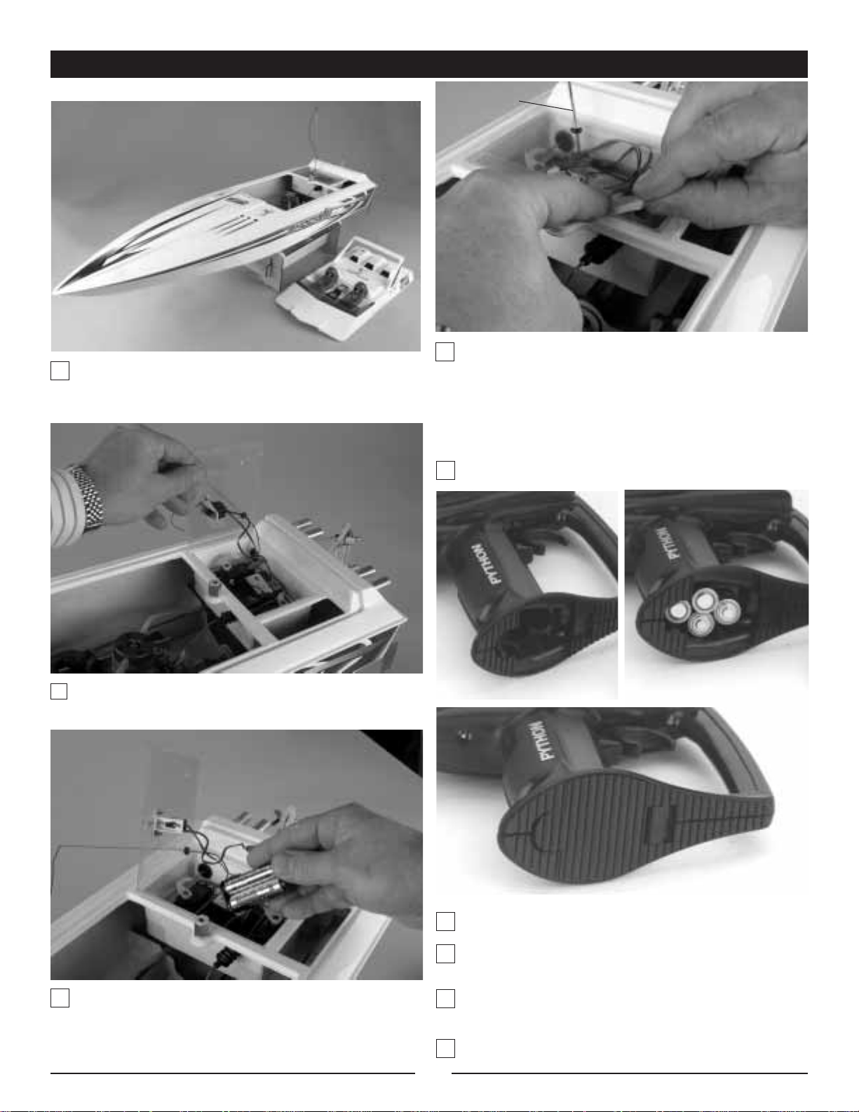
Re-install the battery holder into the radio box and
properly seal the radio box with clear tape. Failure
to properly seal the radio box could result in damage
to your radio equipment. Insert the reciever antenna
tube into the clear lid.
Remove the transmitter from the box.
Remove the battery cover on the bottom of transmitter.
Note the proper polarity and insert 8 “AA” batteries into
the transmitter.
Turn on the radio and confirm that all LEDs illuminate,
indicating proper installation of fully charged batteries.
Turn the radio off.
Transmitter Batteries
4
Section 1: Installation of Receiver and Transmitter Batteries
Remove the knurled aluminum nut that secures the
cockpit. Pull the cockpit off the boat.
Remove the clear lid that covers the radio box.
Remove the dry cell battery holder from the radio box and
unwrap the foam from around the dry cell battery holder.
Install 4 “AA” alkaline batteries as shown. Note the proper
polarity. Wrap the battery box in foam.
Receiver Batteries
Antenna
Tube
Page 5

5
Section 2: Rudder Installation
Section 3: Filling the Fuel Tank
Parts Needed: Rudder and 2.5mm hex screw
We recommend that you use Blue Thunder™20% fuel. For
maximum performance, we recommend Blue Thunder Race
Formula. Blue Thunder fuels are specifically formulated for
excellent power and engine protection.
Locate the fuel tank inside the cockpit area and unscrew the lid.
Use either the DYN2009 Fast Tap
™
quart bottle spout that has been
attached to the quart of fuel or the DYN2003 Fuel Bottle to fill the
fuel tank with your selection of Blue Thunder fuel. After you have
filled the fuel tank and re-installed the lid, wipe away any excess
fuel that may have spilled inside the hull or elsewhere on the boat.
Immediately seal the fuel container by putting the lid back on after
refueling in order to protect the fuel from moisture.
Section 4: Range Checking the JR Python Radio System
Before the first run of the ShockWave™36, you should check
the radio for proper operation and to ensure proper control
movement of the rudder and throttle. Also ensure that the
antenna on the boat is extended properly and that all batteries
are in working condition.
1. With the radio system turned on (transmitter and receiver)
and the transmitter antenna down (engine off), walk off
40 to 50 paces from the ShockWave 36.
2. Have an assistant remain with the boat to check for proper control
movement of the rudder from your transmitter input.
3. If everything appears to be operating correctly, raise the
antenna and start the engine (refer to Section 6 of this manual
and to the separate DYN .32 engine manual). Place the boat in
the water and run it (at about
1
⁄3 throttle) close to the shore-
line. If the radio system is operating properly, you can begin
to run the boat faster and furtheraway from the shoreline.
Note: It is a good idea to range check prior to operating
your boat after any repair, installation of new batteries, or
at the beginning of each boating season.
Step 2. Carefully insert the rudder as shown.
Step 3. Find the flat spot on the rudder. Using the 2.5mm
hex wrench, tighten the hex screw on the flat spot as shown.
Step 1. Locate the stainless steel rudder and 2.5mm
hex screw.
Section 5: Handling Adjustments
Trim Tabs: The trim tabs can greatly enhance the performance of
your ShockWave. To adjust the angle of the trim tabs, use a large
pair of channel lock pliers to carefully bend the tabs as shown.
This must be done carefully so that you do not damage the
transom. If you would like a calmer, more controlled run, carefully
bend the tabs down
1
⁄8”. If your goal is to go faster and to add
excitement, bend the tabs up.
Wake Conditions: It is advisable to run your ShockWave in low to
medium wake conditions to avoid having problems with the boat
overturning. If the conditions are questionable, bend the trim tabs
down a bit to reduce the likelihood of having the boat overturn.
Page 6

Section 6:The Dynamite .32 Marine Engine
Water-Cooled Engine
Because the Dynamite
®
.32 engine is water-cooled and not aircooled, make sure that you do not run the engine for an extended
amount of time outside of the water. Continuously monitor the
water outlet when the boat is running to make sure that water is
flowing through the engine head. If the water does not reach the
head to cool it, the engine will overheat and fail. This will cause
permanent damage to the engine.
Carburetor
The Dynamite carburetor is adjusted at the factory. This
setting should be approximately 1
3
⁄4 –21⁄2 turns open for the
high-speed and 21⁄2 turns open for the low-speed needle. This
should give you a slightly "rich" mixture of fuel to the engine.
This setting is the safest way to break in your engine. For
further details regarding the carburetor, see the Dynamite .32
instruction manual.
Note: When using the pull-starter, never pull the rope out to
its full length as doing so can cause damage and the rope
may not retract. Quick, short pulls of the starter rope are
the best technique to use with the pull-starter.
If the pull-starter becomes very difficult to pull, the engine may be
hydro-locked (flooded). Excessive fuel between the head and
piston will not let the piston travel to TDC (Top Dead Center).
Loosen the glow plug one turn and try to start the engine. If the
engine starts, re-tighten the glow plug with the attached glow
driver while the engine is running. If you are still unable to get
your engine to start, refer to the Troubleshooting Guide (page 7)
in this manual.
You may have to "blip" the throttle on the transmitter (applying
throttle on/off) while trying to start the engine. New engines are
harder to start because of the tight piston/sleeve fit. Never start
an engine at
1
⁄2 to full throttle, as this will cause over-revving
which may cause premature wear and breakage.
During the first tank of fuel, advance the idle via the idle adjustment screw more than normal to prevent stalling at idle due to the
rich fuel mixture for break-in. Pinch the fuel line nearest the
carburetor to stop the engine.
Breaking in Your Engine
The first start-up of the engine is the most critical moment of the
engine’s life, dictating how the engine will perform from that time
forward. Turn on your radio system and attach a fully charged
glow igniter (DYN1925) to the glow plug. Start the engine with the
recoil (pull-start) on the engine.
During break-in, the low-speed needle should be slightly rich and
the high speed needle should be very rich. After a few tanks of
fuel, begin to lean the engine out. Adjust the high-speed needle
1
⁄16 of a turn at a time. It generally takes about five to six tanks of
fuel before you want to lean out the engine until it supplies good
power. Do not skip this process of break-in. Failure to follow
this procedure could damage your new engine. For further
details on breaking in your engine, please see the seperate
Dynamite .32 instruction manual.
Note: It is common for an ABC engine to go through a glow
plug or two during break-in.
Needle Settings
When adjusting the settings, always adjust the needles in small
increments, about
1
⁄16 of a full turn at a time. Do not set the engine
too lean, as it shortens the reliability of the engine.
After you have attained the correct needle settings, the engine will
have a strong sounding, high-pitched whine at full speed, and a
thin trail of blue/white smoke will come from the exhaust.
Idle Adjustment
The last setting to set is the idle screw. To obtain a higher idle,
turn the idle screw clockwise; for lower idle, turn the idle screw
counterclockwise.
Replacement Parts
In the event that you need to replace an engine part, there is a
complete parts listing in the Dynamite .32 instruction manual.
Exploded views will help you to select the correct parts and make
minor repairs.
Head Shims
Several head shims are added at the factory to make the engine
easier to start when new. After break-in, you may remove all but
one of theses shims to increase compression and power.
High-Speed
Needle Valve
Faster Idle
(clockwise)
Idle
Stop Screw
Leaner
Low-Speed
Needle
Valve
Slower Idle
(counterclockwise)
6
Leaner
Fuel Inlet
(Adjustable)
Page 7

7
Troubleshooting Guide
Problem Possible Solution
Engine will not start Improper needle setting: see section 6
Out of fuel: fill fuel tank
Improper fuel: use 20% Blue Thunder
™
Improper glow plug: install proper glow plug
Glow igniter not charged: charge igniter
Dead glow plug: replace
Flooded engine: remove glow plug, invert boat and operate the pull-starter to
remove fuel
Engine starts, then dies Pressure line blocked or unhooked: connect or replace fuel line
Reset needles to baseline setting: see section 6
Engine starts and runs for Bad glow plug: replace
several minutes, then dies Idle speed set too low: see section 6
Improper needle settings: see section 6
Overheated engine: check for clogged or damaged cooling system
Glow plug failed due to lean engine setting: richen carburetor settings and
replace glow plug
Section 7: Maintenance
The Pro Boat™ShockWave™36 should provide many hours of
exciting high-speed racing fun with just minor maintenance.
Preventative maintenance is very important. Taking the time to
ensure that all the set screws and bolts are tight before each
operation of the boat will prevent many problems.
Before operating ShockWave 36
Check that all screws and hardware are securely in place. This is
very important, as the manifold screws will occasionally vibrate
loose during the first initial runs.
Check the propeller for damage in the form of chipping or
cracking. If you find any damage, replace the propeller, as the
damage will effect the performance of the boat and could also
cause safety concerns.
When refueling, always wipe away any excess fuel that may have
spilled into or on the boat.
After operating the ShockWave 36
Wipe off any exhaust residue from the boat. If you operate the
ShockWave 36 in salt water, it is suggested that you thoroughly
rinse the deck, hull, and all the metal hardware with fresh
water, then dry them with a clean towel. After cleaning, coat all
metal parts with a silicone spray lubricant. This will help to
prevent corrosion.
Ensure that the radio box and equipment inside is dry.
Page 8

Section 7: Maintenance (cont.)
Lubrication
It is important to lubricate the drive shaft of the ShockWave™36
with silicone cable grease after every two hours of operation.
You can purchase this silicone grease at your local hobby store.
To lubricate the drive shaft, follow these simple instructions.
Carefully note how the drive shaft and prop are factory
installed. This is important so that when you have finished
lubricating the drive shaft, you can correctly re-install the
drive shaft.
Loosen (do not remove) the retaining nut by holding the
collet with a 17mm wrench and unscrew the retaining nut
with another 17mm wrench or crescent wrench.
Carefully remove the drive shaft.
Retaining
Nut
Collet
Flywheel
8
Liberally lubricate the entire length of the drive shaft with
silicone cable grease as shown.
Carefully re-install the drive shaft, making certain that you
insert the flex shaft
7
⁄16” to 1⁄2” into the collet and secure.
Propeller
Propeller
Nut
Lock Washer
Drive Dog
Nylon Propeller
Washer
Page 9
9
Section 8: ShockWave 36 Replacement Parts
In the event that you need to purchase replacement parts for your engine or the ShockWave™36, please see your local hobby store.
You can also purchase them from Horizon Hobby by calling 1-800-338-4639 or shop online @ www.horizonhobby.com
Stock # Description
PRB2051 Hull
PRB2052 Flex Cable
PRB2053 Engine Mount
PRB2054 Vibration Dampeners (4)
PRB2055 Manifold
PRB2056 Tuned Pipe
PRB2057 Flywheel
PRB2058 Drive Dog and Joint
PRB2059 Propeller Nut
PRB2060 Rudder Bracket and Accy
PRB2061 Rudder
PRB2062 Prop Bracket and Accy
PRB2063 Trim Fin (2)
PRB2064 Turn Fin (2)
PRB2065 Exhaust Port
PRB2066 Receiver Switch Assembly
PRB2067 Fuel Tank Complete
PRB2068 Water Outlet and Nut
PRB2069 Throttle Linkage
PRB2070 Rudder Linkage
PRB2071 Cooling Water Tubing
PRB2072 Exhaust Coupler
PRB2073 Rubber Boot (2)
PRB2074 Radio Box Cover
PRB2075 Antenna Tube
PRB2076 Boat Stand
PRB2077 Servo Plate
PRB2078 Decals
PRB2079 Collet
PRB2080 Teflon Liner
PRB2081 Screw/Nut Set Complete
PRB2082 Cockpit w/ Pilots
PRB2083 Cockpit Nut
PRB2084 Windshield
PRB2085 Wing
PRAB230 Propeller 1.90 x 3.0 Bronze
Appendix
Photo 1 Photo 3
Photo 2
Photo 4
Fuel Tank
Fuel Line
Glow Plug
Pull Starter
Water-Cooled Head
Cooling Water Line
Cooling Water Line
Cooling Water
Outlet
Propeller
Carburetor
Coupler
Exhaust
Manifold
Cooling Water
Pick-Up Tube
Cooling Water Line
Skid Fin
Rudder
Trim Tab
Exhaust
Port
Skid Fin
Trim Tab
Rudder Linkage
Page 10

• Professionally painted
and detailed fiberglass hull
• Speeds up to 30 mph
• Water-cooled Dynamite
®
.15 Marine nitro engine
• JR®Python pistol-grip
radio system installed
• Length: 27.5 inches
Look for these other fine Pro Boat™models at your local hobby dealer.
PRB2200 Miss Budweiser 1/12 Unlimited Hydro RTR
PRB2250 Miss Budweiser 1/8 Unlimited Hydro RTR
PRB2000 ShockWave
™
55” Deep-V RTR
with Zenoah G-26
PRB2400 Sanibel
™
36-600 RTR Sailboat
PRB2300 Riptide
™
Watercraft EP RTR
PRB2240 1/12 Miss Budweiser Boat Tote
• JR XR3i FM pistol-grip radio system installed
• Professionally painted and decaled fiberglass hull
• Zenoah®G26 marine engine installed
• Stock speeds in excess of 40 mph
• Length: 44.25 inches
• JR XR3i FM pistol-grip radio system installed
• Professionally painted and decaled fiberglass hull
• 26cc Zenoah G26 Marine Engine
• Length: 55 inches
• Genuine Prather running hardware
•Preinstalled JR Beat Gear
2-stick 2-channel system
with sail winch
•Handcrafted fiberglass
composite hull
•Detachable 2-piece mast
of anodized aluminum
•Assembles in under
2 hours
• Length: 36 inches
• Equipped with a fan-cooled 550-size motor,
waterproof electronic speed control with reverse, two-stick FM
transmitter and a painted vinyl rider figure
• Extra-wide 9-inch beam
Page 11

MADE IN CHINA
© 2004 Horizon Hobby, Inc.
www.horizonhobby.com
6605
Notes
 Loading...