

Page 1
Specifications
Length: ................................................................................................. 29 in (725mm)
Beam: ................................................................................................... 10 in (250mm)
Radio: .................................................................. 2-Stick 27 mHz FM Radio System
Motor: ......................................................................................... 550 Electric Motor
Motor Control: .......... Waterproof Electronic Speed Control (Forward Only)
INSTRUCTION MANUAL
Classic Runabout
™
EP RTR
Page 2
Thank you for purchasing the Pro Boat™ Classic
Runabout™ Ready-To-Run boat. Please read these
instructions carefully before attempting to operate
the boat.
The Classic Runabout comes ready-to-run with an FM
radio system and electronic speed controller already
installed. All assembly is done at the factory, allowing
you to quickly get the boat running.
Additional Items Needed
You will need to purchase the following items to get
the boat on the water:
• 8 “AA” alkaline batteries for the
radio transmitter
• 7.2V Ni-Cd Battery Pack with
Tamiya Connector (DYN1000)
• Ni-Cd Battery Fast Charger (DYN4010)
Classic Runabout™ EP RTR Instruction Manual
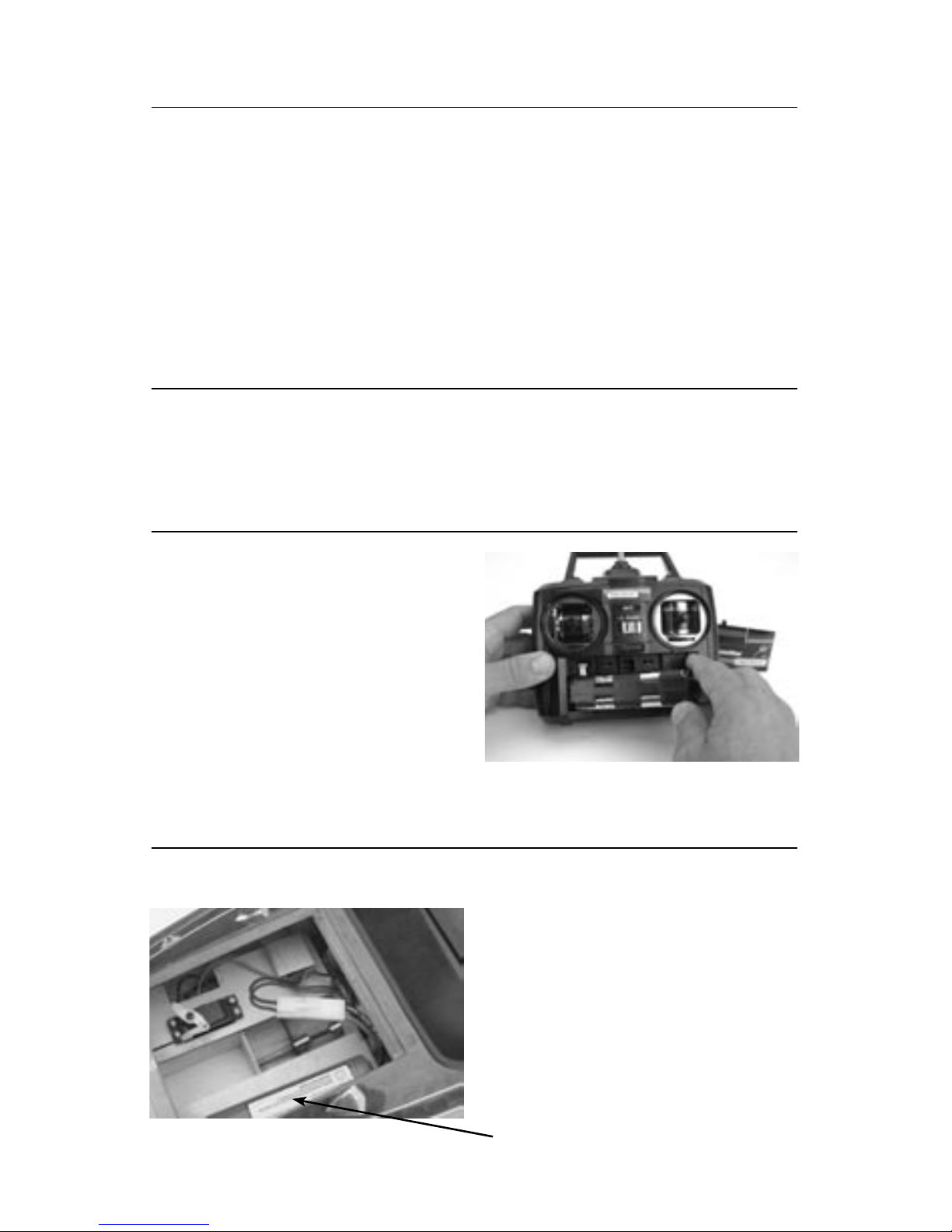
1. Carefully lift the deck lid to expose the battery
compartment. (See Figure 2)
2. Install a fully charged 7.2-volt Ni-Cd battery pack
into the hull. (Follow the instructions included with
the fast charger to ensure a safe charge.) Secure the
battery with mounting straps.
3. Connect the battery plug to the matching connector
on the electronic speed control.
4. Replace the hatch.
Installation of the 7.2V Ni-Cd Battery
1. Carefully remove the boat and radio transmitter
from the box.
2. Inspect the boat. If you notice damage from
shipping, please contact the hobby shop where
you purchased it.
Inspection
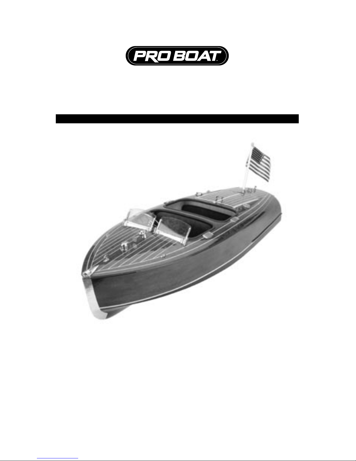
1. Install 8 “AA” alkaline batteries into the transmitter.
Be sure each battery cell is installed in the proper
polarity. The polarity is marked at each cell’s
location inside the transmitter. (Figure 1)
2. Slide the battery cover in place and turn on the
transmitter. The LED will light if the batteries are in
good condition and installed properly.
3. Turn off the transmitter.
Installation of Transmitter Batteries
Figure 1
Figure 2
7.2 Volt Battery Pack
Page 3

1. Turn on the transmitter then the receiver and check
for correct operation. Move the right stick on the
transmitter left and right. The rudder should move
relative to the stick movement. (See Figure 3)
2. With the propeller free from any objects, give some
throttle input to ensure that the motor is working. If
everything appears to be functioning correctly, you
are ready to run your boat! If any of these functions
are reversed, change the respective reversing switch
position. (See Figure 4)
Note: If you are transporting the boat, disconnect the
battery from the speed controller and then turn the
radio off until you are ready to run the boat. Once
ready, simply turn the radio on and plug the battery
into the speed controller, making sure that the throttle
stick is in the neutral position. Read the Electronic
Speed Control instructions (included with the boat)
before operating.
Checking the Radio System
1. Make sure that the radio is on and the battery is
plugged into the speed controller and motor.
2. Carefully place the boat in the water. Pilot the boat
at slow speeds, staying close to the shoreline to
ensure that you have good control and that the boat
is functioning correctly.
3. Be certain to avoid all objects in the water.
Once you feel comfortable with the control of
the boat, it is safe to go further from the shore
and at faster speeds.
4. If the boat is losing speed, steer the boat carefully
back to shore. It will be necessary to replace or
recharge the battery before running your boat again.
5. If the boat tends to drift one direction during
operation, adjust the steering trim to compensate.
(See Figure 4)
Testing the Boat in the Water
Before and at the end of each run, make sure that
all screws are tight and that the propeller is free from
any entanglement.
Note: Running the Classic Runabout™ in salt water
could cause parts to corrode. Rinse thoroughly with
fresh water after each use.
If you have any questions concerning the setup or
running of the Classic Runabout, please call the
Horizon Service Center at (877) 504-0233.
Maintenance
Rudder Reversing Switch
Throttle Reversing Switch
Forward
Left
On/Off
Right
Reverse
Figure 4
Throttle Trim
Steering Trim
Page 4

Pro Boat warranties this product to be free from defects
in materials and workmanship at the date of purchase.
This warranty is limited to the original purchaser of
this boat and is not transferable. This warranty will not
cover modifications, misuse or service performed by
an unauthorized service center.
Your warranty may be voided if:
• Reverse voltage is applied to your Pro Boat ESC
(e.g., connecting battery pack backward, plugging
battery into the motor connector wires, etc.)
• Alteration or removal of the battery plug or
connectors
• Allowing your wires to become frayed or shorted
• Use of less than 4-cell (4.8-volt) or more than 8-cell
(9.6-volt) battery packs
• Tampering with any of the electronic components
• Crash Damage
Under no circumstances will the buyer be entitled to
consequential or incidental damages. This limited
warranty gives you specific legal rights; you also have
other rights that may vary from state to state. If your
Classic Runabout is in need of repair, please ship it
freight prepaid to:
Horizon Service Center
ATTN: PRO BOAT Service
4105 Fieldstone Road
Champaign, Illinois 61822
Phone toll-free 1-877-504-0233
Include your complete name and address
information inside the carton, as well as on the return
address area. Include a brief summary of the problem.
Date your correspondence and be sure to print your
name and address on this enclosure. Also, include a
phone number where you can be reached during the
business day.
To receive warranty service, your original dated
sales receipt must be included to verify your proof of
purchase date. Providing warranty conditions have
been met, your Pro Boat Classic Runabout will be
repaired or replaced free of charge. Phone toll-free
1-877-504-0233.
Non-Warranty Repairs
Should your repair cost exceed 50% of the retail
purchase price, you will be provided with an estimate
advising you of your options. Any return freight for
non-warranty repairs will be billed to the consumer.
For non-warranty repairs, please advise us of the credit
card you prefer to use. Horizon Service Center accepts
Visa or MasterCard. Please include your card number
and expiration date. Horizon Service Center also
accepts money orders.
Limited Warranty
part # Description
PRB2601 Hull Accessories: Runabout
PRB2602 Steering Wheel: Runabout
PRB2603 Flag Pole: Runabout
PRB2604 Rudder: Runabout
PRB2605 Stuffing Box: Runabout
PRB2606 Propeller Shaft: Runabout
PRB2607 Drive Dog: SW26, Sndcr, Runabout
PRB2608 Rudder Arm: Runabout
PRB2609 Rudder Pushrod: Runabout
PRB2610 Motor Mount: Runabout
PRB2611 Front Bench: Runabout
PRB2612 Rear Bench: Runabout
PRB2613 Windshield: Runabout
PRB2614 Trim Edging
PRB2615 Hatch Seal: Runabout
PRB2616 Boat Stand: Runabout
PRB2618 Decal and Flags: Runabout
PRB2619 Instruction Manual: Runabout
PRB2620 Hull only: Runabout
PRB2621 Hatch Lid: Runabout
PRB2311 Transmitter: ProBoat
PRB2312 Receiver: ProBoat
PRB2313 MC-300 Servo: ProBoat
PRB2114 Waterproof ESC forward only: 4.8V-9.6V
PRB2155 550 Motor: SW26, Runabout
PRB2105 Propeller: SW26, sndcr, Runabout
PRB2103 Dogbone and joints: SW26, Sndcr,
Runabout
Replacement Parts List
© Copyright 2004, Horizon Hobby, Inc.
www.horizonhobby.com
7283
 Loading...