

Page 1
1
VISTEK V6402 FRAME
SYNCHRONISER,
V6404 DOWN CONVERTER,
V6406 UP CONVERTER,
V6408 CROSS CONVERTER and
V6418 CONVERTER
USER GUIDE
www.pro-bel.com
Page 2

V6402, V6404, V6406,V6408
and V6418 HD converters
2 Issue 6
Contents
1 DESCRIPTION...........................................................................................................5
1.1 General............................................................................................................5
1.2 Block Diagram................................................................................................7
1.3 Supported Video Standards..........................................................................8
1.3.1 V6402 HD Frame Synchroniser.............................................................8
1.3.2 V6404 HD Down Converter.................................................................10
1.3.3 V6406 HD Up Converter......................................................................11
1.3.4 V6408 HD Cross Converter.................................................................12
1.3.5 V6418 HD Converter...........................................................................13
2 INSTALLATION.......................................................................................................15
2.1 Rear Panels...................................................................................................15
2.2 Connections..................................................................................................16
2.3 Module and Environmental Specifications................................................17
2.4 Signal Specifications...................................................................................17
2.5 Timing Adjustment Ranges.........................................................................18
2.5.1 Synchroniser Mode..............................................................................18
2.5.2 Delay Mode.........................................................................................19
2.5.3 Minimum Delay (Intrinsic Delay)..........................................................20
2.6 Hardware.......................................................................................................21
2.6.1 The PCB..............................................................................................21
2.6.2 Links and Switches..............................................................................21
2.6.3 Fuse....................................................................................................22
2.6.4 Flash Memory Card.............................................................................22
2.7 Front Panel....................................................................................................23
2.7.1 Direct Indications.................................................................................23
2.7.2 Display and Switches..........................................................................24
2.7.3 Remote/Local Control..........................................................................24
3 SYSTEM OPERATION.............................................................................................25
3.1 Local Control................................................................................................25
3.1.1 Start up................................................................................................25
3.1.2 Option Abbreviations...........................................................................25
3.1.3 Menu Control.......................................................................................26
3.1.4 Menu Examples...................................................................................27
3.1.5 Sleep...................................................................................................27
Page 3

V6402, V6404, V6406, V6408
and V6418 HD converters
HU-V6402&4&6&8&18 3
3.2 Common Features to all Units.....................................................................28
3.2.1 SDI Inputs............................................................................................28
3.2.2 SDI Reclocked & Buffered Output.......................................................28
3.2.3 SDI Main Outputs................................................................................28
3.2.4 Video Reference..................................................................................28
3.2.5 Standard Detection..............................................................................28
3.2.6 TRS Signals........................................................................................29
3.2.7 EDH (SD operation only).....................................................................29
3.2.8 Illegal Codes.......................................................................................29
3.2.9 Horizontal and Vertical Blanking Interval Data (HANC and VANC)....29
3.2.10 SDI Input Fail......................................................................................30
3.2.11 Video Reference Fail...........................................................................30
3.2.12 GPI Configuration................................................................................30
3.2.13 Video Reference Mismatch.................................................................31
3.2.14 Delay Signal........................................................................................31
3.2.15 VCO Centre Frequency.......................................................................32
3.2.16 Version Numbers.................................................................................32
3.2.17 Memory Size........................................................................................32
3.2.18 Display Sleep......................................................................................32
3.2.19 Display Brightness..............................................................................32
3.3 Module Specific Functions...........................................................................33
3.3.1 Manual Freeze....................................................................................33
3.3.2 Timing & Delay Control.......................................................................33
3.3.3 Test Pattern Generator (TPG).............................................................38
3.3.4 Conversion Modes..............................................................................41
3.3.5 Down Converter Aspect Ratios...........................................................42
3.3.6 Up/Cross Converter Aspect Ratios.....................................................43
3.3.7 Cross- & Up-Converter Output Standard Selection.............................43
3.3.8 V6418 Short Delay Mode....................................................................44
3.4 Video Processing Amplifier..........................................................................45
3.4.1 Video Gain..........................................................................................45
3.4.2 Chroma Gain.......................................................................................45
3.4.3 Black Level..........................................................................................45
3.4.4 Hue Shift..............................................................................................45
3.4.5 Dynamic Rounding..............................................................................45
3.4.6 Limiting................................................................................................46
3.4.7 Fade to Black......................................................................................46
3.5 Audio Handling..............................................................................................47
3.5.1 Audio Group Selection........................................................................47
3.5.2 Audio Group Status.............................................................................47
3.6 Audio Processing..........................................................................................48
3.6.1 Audio Insertion Delay..........................................................................48
3.6.2 Tracking Delay....................................................................................48
Page 4

V6402, V6404, V6406,V6408
and V6418 HD converters
4 Issue 6
3.7 Closed Captions...........................................................................................49
3.7.1 SD Captions........................................................................................49
3.7.2 HD Captions........................................................................................49
3.7.3 Output line selection on the V6418.....................................................50
3.7.4 Caption Status.....................................................................................50
4 CALIBRATION.........................................................................................................51
4.1 Set-Up............................................................................................................51
4.2 Free-Run Frequency.....................................................................................51
5 CONTROLS.............................................................................................................52
5.1 Video Processing – VIDEO..........................................................................53
5.2 Operating Conditions – STATUS................................................................56
5.3 Engineering – ENG’ING................................................................................58
5.4 Calibration – CALIB......................................................................................59
5.5 Configuration – CONFIG..............................................................................60
5.6 Video Proc Amp – PROC AMP.....................................................................63
5.7 Audio Handling – AUDIO.............................................................................64
5.8 Closed Captioning – CCAPTION.................................................................65
6 APPENDIX A............................................................................................................66
6.1 Trouble Shooting Guide (Frequently Asked Questions)..........................66
6.2 Initialization, Power On-Selftest & Error Messages..................................68
6.2.1 Board Initialization Sequence..............................................................68
6.2.2 SDRAM Test........................................................................................69
6.3 Menu Structures...........................................................................................69
6.3.1 V6402 HD Frame Synchroniser Menu Structure.................................70
6.3.2 V6404 HD Down Converter Menu Structure........................................71
6.3.3 V6406 HD Up Converter Menu Structure............................................72
6.3.4 V6408 HD Cross Converter Menu Structure.......................................73
6.3.5 V6418 HD Converter Menu Structure..................................................74
Page 5

V6402, V6404, V6406, V6408
and V6418 HD converters
HU-V6402&4&6&8&18 5
1 DESCRIPTION
The modules described in this manual form part of the Vistek 1600 range of interface products. Although
they process High Definition (HD) video signals, they are fully compatible with all other products in the
range in terms of their form factor, power supply requirements and control interface. Each is a 3U high
card that can be fitted into a V1606 rack or a V6011 '1-Box', from which it obtains its power and control. A
passive rear module is required for all signal interconnections.
This manual covers the following modules:
V6402 HD Frame Synchroniser
V6404 HD Down Converter
V6406 HD Up Converter
V6408 HD Cross Converter
V6418 HD Converter
These modules are based on a common platform, with a variety of Add-Ons available:
VP: Video Proc Amp
SY: Frame Synchroniser (inherent for V6402)
FD: Field/Frame Delay (requires the SY option to be enabled)
CP: Closed Captioning
AH: Audio Handling
1.1 General
The V6402 HD Frame Synchroniser re-times an HD or SD SDI signal to an external reference signal and
allows the operator to offset the output from the reference by a set amount both horizontally and vertically.
The horizontal adjustment is in single clock steps over a whole line and the vertical adjustment is in lines
with a range of ±255 lines. The Frame Synchroniser will occasionally repeat a frame or drop a frame in
order to keep pace with the external reference applied. Ancillary data in the horizontal and vertical
blanking intervals - such as embedded Audio - remain unaltered, but can be also forced to be blanked. A
built-in Test Pattern Generator (TPG) offers a choice of commonly used test patterns for system integrity
tests. Without an external reference, the unit can operate as an adjustable delay module, allowing the
operator to set the input to output delay pixel accurate from a minimum delay of roughly one video line up
to an arbitrary number of fields/frames, provided that the Field/Frame Delay option is enabled. The unit
automatically detects the input signal standard and operates accordingly. Available options for the V6402
are: VP and FD.
The V6404 HD Down Converter takes an HD input signal and converts it to a Standard Definition (SD)
output at the same frame rate as the input. While the unit handles all the interlacing, filtering and scaling
required, it does not change the frame rate. Therefore, both the input and output standards must have the
same frame rate. The unit automatically detects the input signal standard and sets the output standard,
i.e. 525 lines @ 59.94Hz or 625 lines @ 50Hz, accordingly. The operator can select between different
aspect ratios (e.g. anamorphic, letterbox, centre-cutout). If the detected input standard is SD, the unit
switches automatically into a bypass mode where it maintains the same processing delay that is normally
introduced by the down-conversion process. If the module comes with the Audio Handling (AH) option
fitted, embedded Audio information will be retained by de-embedding it in the HD domain and reembedding it in the SD domain. Available options for the V6404 are: VP, SY, FD, CP and AH.
Page 6

V6402, V6404, V6406,V6408
and V6418 HD converters
6 Issue 6
The V6406 HD Up Converter takes an SD input signal and converts it to a High Definition (HD) output at
the same frame rate as the input. The V6406’s 3 dimensional, motion adaptive filtering offers far superior
conversion compared with the V6408’s 2 dimensional algorithm. While the unit handles all the interlacing,
filtering and scaling required, it does not change the frame rate. Therefore, both the input and output
standards must have the same frame rate. The operator can select between different aspect ratios (e.g.
anamorphic, pillarbox, centre-cutout). If the module comes with the Audio Handling (AH) option fitted,
embedded Audio information will be retained by de-embedding it in the SD domain, and re-embedding it in
the HD domain. Available options for the V6406 are: VP, SY, FD, CP and AH.
The V6408 HD Cross Converter operates within the High Definition domain and in general converts
between the interlaced and progressively scanned formats (720p ↔ 1080i). The unit automatically detects
the input signal standard, but the operator must select the output standard from a list of supported
standards. Furthermore, the V6408 can perform good quality up-conversions from SD to HD, with a
choice of aspect ratios (e.g. anamorphic, pillarbox, centre-cutout). For superior performance, broadcast
quality up-conversions, please consider using Vistek's V6406 HD Up Converter. For all up- and crossconversions, embedded Audio information will be retained if the module comes with the Audio Handling
(AH) option fitted. Available options for the V6408 are: VP, SY, FD, CP and AH.
The V6418 HD Converter integrates the functionality of the V6404 Down Converter and the V6408
Cross/Up Converter modules, with an additional Short Delay (< 1 ms) Down Conversion mode for
monitoring purposes. The unit automatically detects the input signal standard, but the operator must select
the output standard from a list of supported standards, or select the up/down operation mode. The V6418
performs the required up-, down- or cross-conversion according to the input/output standards combination.
If the module comes with the Audio Handling (AH) option fitted, embedded Audio information will be
retained by de-embedding it in the input domain, and re-embedding it in the output domain. Available
options for the V6418 are: VP, SY, FD, CP and AH. When using Short Delay Down Conversion mode, only
the VP, CP and AH options are available. Also the V6302/AP Advanced Audio Processor can not be
utilised in Short Delay Down Conversion mode.
All units have two independent inputs, which can be selected either on the front panel or remotely via
Vistek's control interface 'DART'. They also have a fully re-clocked and buffered output, which is after the
input signal selection. Generally it is recommended to terminate unused input BNCs in order to improve
the unit’s noise susceptibility.
The reference input has two BNCs, so a passive loop-through is available. The reference can be either a
conventional Black & Burst signal (sometimes known as bi-level sync) or a tri-level sync, which is a newer
signal specifically for synchronising HD signals. The Frame Synchroniser (or any other module with the
'SY' option enabled) will automatically detect which type is being used and adapt accordingly. A 75Ω
reference termination can be selected using a switch on the I/O Daughter Board.
Modules with a Frame Synchroniser, i.e. the V6402 or V6404/06/08/18 with the SY option fitted, come with
a tracking delay output on a BNC which can be used in connection with a 3rd party Audio Processor. If a
V64xx is used in combination with Vistek's V6302 Advanced Audio Processor and a dedicated doublewidth rear panel, the tracking delay information will be passed internally from the Frame Synchroniser to
the Audio Processor.
Common for all modules are two (identical) Output BNCs, capable of driving either SD or HD SDI.
There is a versatile front panel with an alphanumeric display, which lets the operator set up a large
number of parameters and read the internal status of the unit. The front panel operates in the same way
as many of the more complex units in the range.
Page 7
V6402, V6404, V6406, V6408
and V6418 HD converters
HU-V6402&4&6&8&18 7
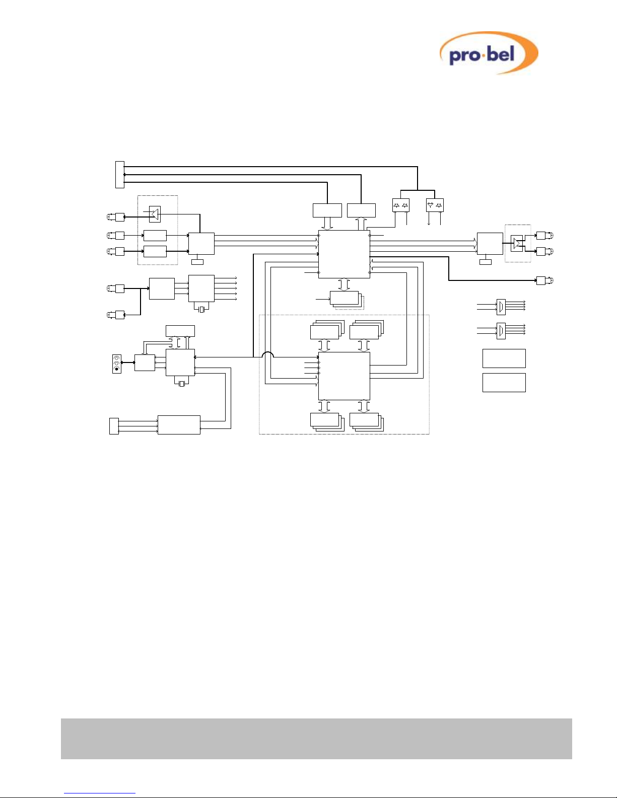
1.2 Block Diagram
Ext. Flash
LVDS Video In (3 pairs Data + 1 pair Clock)
Tri-Level Sync or
Black & Burst
HD SDI Input2
3.3V, 1.8V, 1.5V
Ref F
De-Serializer
I/O Daughter Card
SD SDI Output2
I/O Daughter Card
2M x 32
Clock-Generator
Genlock
2D Scaler
Cable EQ
Cable Driver
V
to/from V6302
LVDS Misc I/O (Clk, F, RxD, TxD, etc.)
Ref V
Ref H
DLY Pulse Output
Ref Data EEProm
System Control Interface (DART)
&
SDRAM
&
F
20-Bit YUV
Multi-Rate
V6402 / V6404 / V6408 / V6418
H
Reclocker
Sync Separator
I2C Interface
Reference Input
Power Supplies
DART
Cable Driver
PLL
SD SDI Output1
Cable EQ
HD SDI Input1
Reclocked HD Output
2M x 32
SDRAM
SDRAM
2M x 32
SDRAM
2M x 32
Audio De-Embedding
Frame-Sync
Loop Through Ref.
Serializer
VCO VCO
TPG
20
-Bit
20
-Bit
20
-Bit
20
-Bit
Ref CLK27
Internal I2C
LVDS Video Out (3 pairs Data + 1 pair Clock)
JTAG
via Rear Panel
Serial Control Bus
'41 Style Front Panel
Control & Status Indication
FPGA
H8S/2633
Hitachi
Input CLK
F
Ref CLKB
Ref CLK74
Scaler Output CLK
Output CLK
Ref CLK74
Ref CLK A
IN_CLK
PRC_CLK
CLKOUT
RxD
20-Bit YUV
20-Bit YUV
30-Bit RGB or 10-Bit YUV (muxed)
21-Bit LVDS Rx 21-Bit LVDS Tx
21
-Bit
OUT_CLK
21
-Bit
Ref CLK B
Ref CLK74
SDRAM
64
-Bit
Down- & CrossConverter Option
2M x 32
Serial Control
Serial Control
CPLD
14.7456MHz
27MHz
Ref CLK27
Ref CLK74
(not fitted on V6402)
(Audio Processor)
Ref CLK27
Ref CLK74
Ref CLK74
Ref CLK27
Ref CLK A
Ref CLK B
Clock Distribution
Ref CLK A
Ref CLK A
Ref CLK B
Ref CLK B
Ref CLK A
Ref CLK B
TxD
between H8's on V640x and V6302
Asynchronous Serial Comms Port
27/74MHz Clock
74/27MHz Clock
Frame Store Options:
(84-Bit wide optional)
96MByte Max (3x 8Mx32)
16MByte Min (2x 2Mx32)
'Beagle'
Audio Re-Embedding
Page 8
V6402, V6404, V6406,V6408
and V6418 HD converters
8 Issue 6
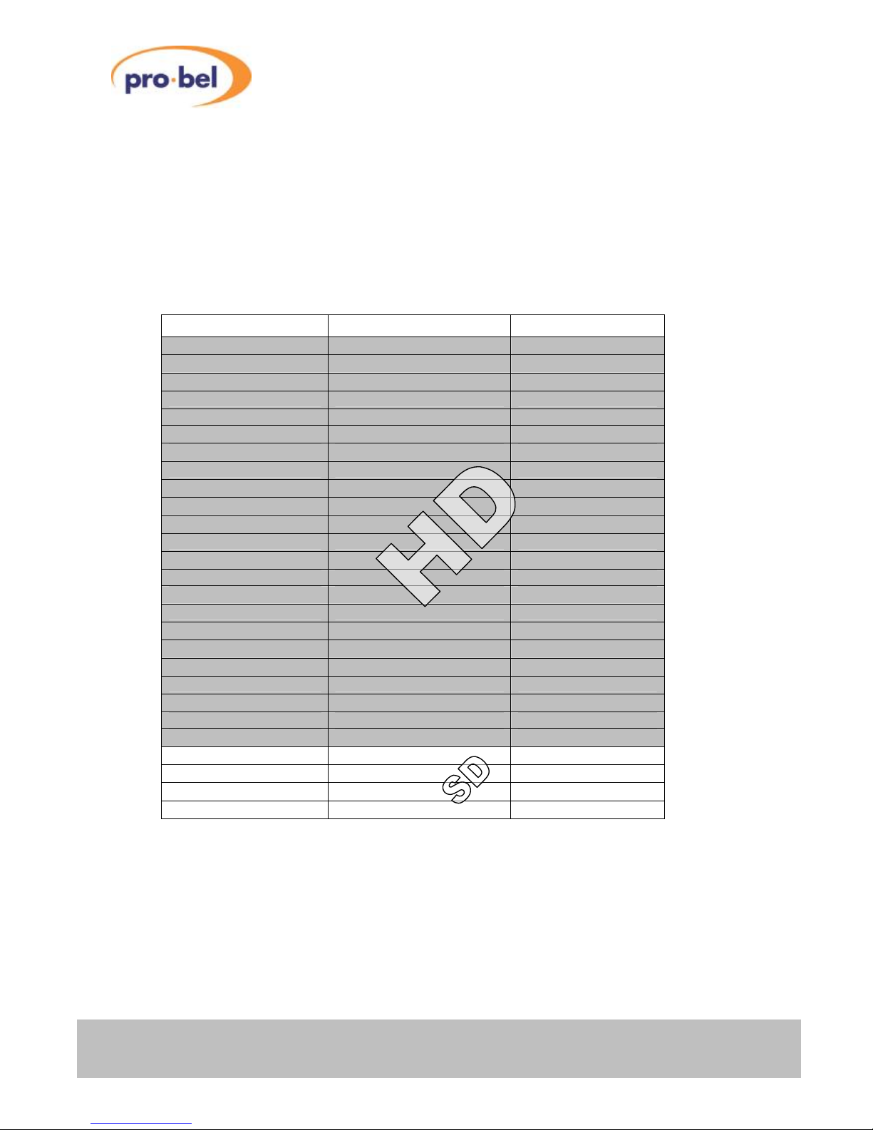
1.3 Supported Video Standards
These units have been designed to operate using all the current Standard Definition and High Definition
Standards based on field and frame rates of 23.98Hz, 24Hz, 25Hz, 29.97Hz, 30Hz, 50Hz, 59.94Hz and
60Hz. The Bit Serial Interface for all listed HD modes is in accordance with SMPTE specification 292M.
For all SD modes, the Serial Digital Interface is in accordance with ANSI/SMPTE 259M.
1.3.1 V6402 HD Frame Synchroniser
Supported Video I/O Standards at the time of printing (FPGA Firmware Version V05.04)
Tektronix Definition SMPTE Colloquial
1920x1080/60/2:1 274M - 4 1080i60
1920x1080/59.94/2:1 274M - 5 1080i59
1920x1080/50/2:1 274M - 6 1080i50
1920x1080/30/1:1 274M - 7 1080p30
1920x1080/29.97/1:1 274M - 8 1080p29
1920x1080/25/1:1 274M - 9 1080p25
1920x1080/24/1:1 274M - 10 1080p24
1920x1080/23.98/1:1 274M - 11 1080p23
1920x1080/24/1:1SF RP211 - 15 1080sf24
1920x1080/23.98/1:1SF RP211 - 16 1080sf23
1280x720/60/1:1 296M 720p60
1280x720/59.94/1:1 296M 720p59
1280x720/50/1:1 296M 720p50
1280x720/30/1:1 296M 720p30
1280x720/29.97/1:1 296M 720p29
1280x720/25/1:1 296M 720p25
1280x720/24/1:1 296M 720p24
1280x720/23.98/1:1 296M 720p23
1920x1035/60/2:1 260M 1035i60
1920x1035/59.94/2:1 260M 1035i59
625/50/2:1 125/259M 625i50
525/59.94/2:1 125/259M 525i59
Note: The ‘colloquial’ label is how they are referred to in this manual.
Page 9
V6402, V6404, V6406, V6408
and V6418 HD converters
HU-V6402&4&6&8&18 9
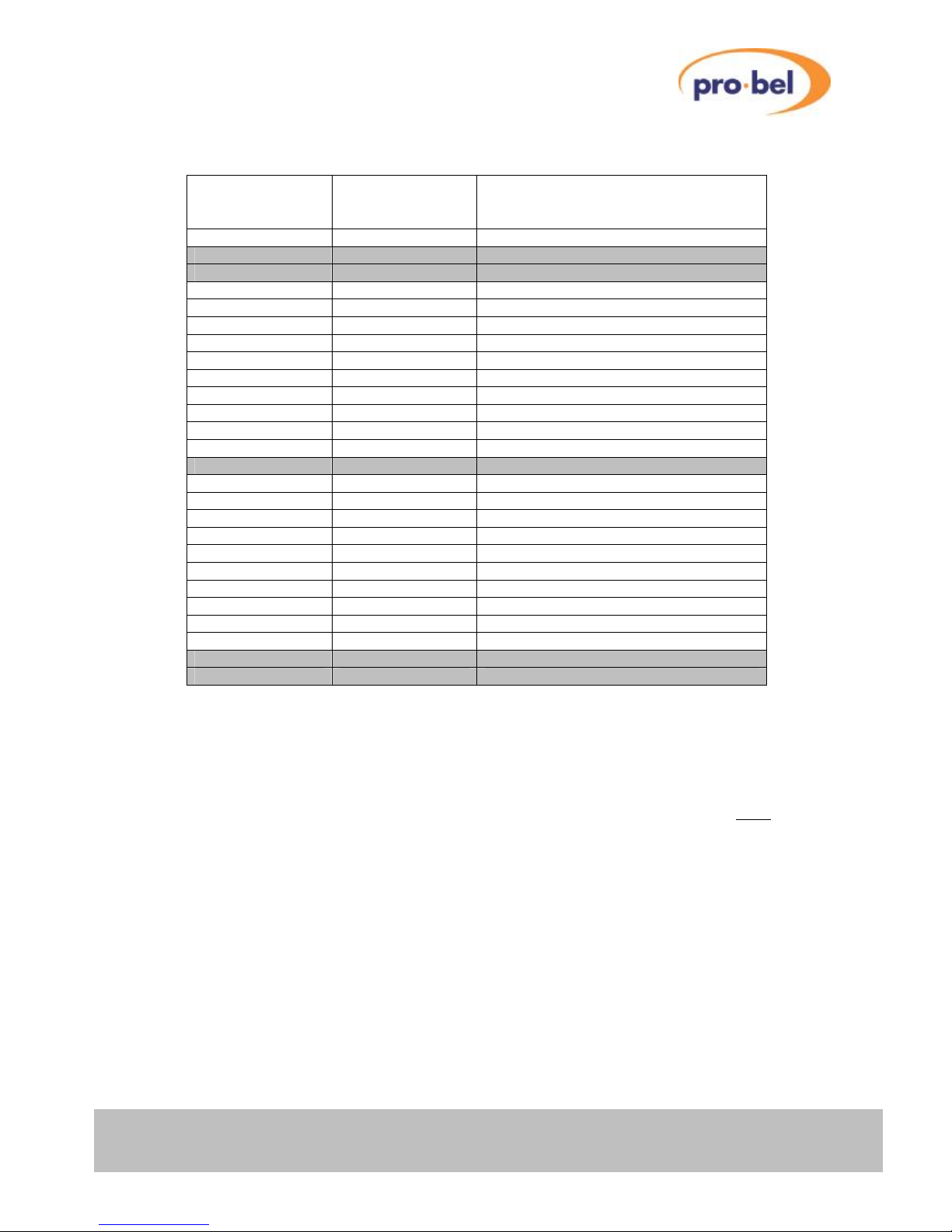
Supported Reference Standards
Standard Sync Type Compatible Video Input
Frame- or Field Rates
1080i60 Tri-Level 30Hz, 60Hz
1080i59 Tri-Level 29.97Hz, 59.94Hz
1080i50 Tri-Level 25Hz, 50Hz
1080p30 Tri-Level 30Hz, 60Hz
1080p29 Tri-Level 29.97Hz, 59.94Hz
1080p25 Tri-Level 25Hz, 50Hz
1080p24 Tri-Level 24Hz
1080p23 Tri-Level 23.98Hz
1080sf24 Tri-Level 24Hz
1080sf23 Tri-Level 23.98Hz
720p60 Tri-Level 30Hz, 60Hz
720p59 Tri-Level 29.97Hz, 59.94Hz
720p50 Tri-Level 25Hz, 50Hz
720p30 Tri-Level 30Hz, 60Hz
720p29 Tri-Level 29.97Hz, 59.94Hz
720p25 Tri-Level 25Hz, 50Hz
720p24 Tri-Level 24Hz
720p23 Tri-Level 23.98Hz
1035i60 Tri-Level 30Hz, 60Hz
1035i59 Tri-Level 29.97Hz, 59.94Hz
625i50 Black & Burst 25Hz, 50Hz
525i59 Black & Burst 29.97Hz, 59.94Hz
The grey shaded rows highlight the most commonly used Reference Standards in today's Studio or
Transmission environments.
It should be noted that the external Reference Input and the Video Input do not have to be of the same
standard! It is however important that there is a match between the field- or frame-rates, since none of the
V64xx modules performs field- or frame-rate conversions (e.g. 50Hz ↔ 59.94Hz conversion is not
supported).
Page 10
V6402, V6404, V6406,V6408
and V6418 HD converters
10 Issue 6
1.3.2 V6404 HD Down Converter
Supported conversion modes at the time of printing (FPGA Firmware Version V05.04)
Input Standard Output Standard Aspect Ratios
1080i59 525i59
1035i59 525i59
720p59 525i59
1080i50 625i50
720p50 625i50
4:3 Anamorphic
16:9 Letterbox
14:9 Letterbox
4:3 Centre-Cutout
525i59 525i59 n.a.
625i50 625i50 n.a.
Furthermore, the V6404 HD Down Converter performs the colourspace conversion between the HD and
the SD domain in accordance with the following standards:
ITU-R BT.709-5 (HD)
ITU-R BT.601-5 (SD)
F
Things to remember:
The V6404 cannot perform field- or frame-rate conversions! When used in connection with the 'SY'
option, the Reference's frame rate must either match the Video Input's field- or frame-rate or must be an
integer fraction there from.
Page 11
V6402, V6404, V6406, V6408
and V6418 HD converters
HU-V6402&4&6&8&18 11
1.3.3 V6406 HD Up Converter
Supported conversion modes at the time of printing
Input Standard Output Standard Aspect Ratios
525i59 720p59
1080i59
625i50 720p50
1080i50
16:9 Anamorphic
4:3 Pillarbox
14:9 Centre-Cutout
16:9 Centre-Cutout
Furthermore, the V6406 HD Up Converter performs the colourspace conversion between the SD and the
HD domain in accordance with the following standards:
ITU-R BT.601-5 (SD)
ITU-R BT.709-5 (HD)
F
Things to remember:
The V6406 cannot perform field- or frame-rate conversions! When used in connection with the 'SY'
option, the Reference's frame rate must either match the Video Input's field- or frame-rate or must be an
integer fraction there from.
Page 12
V6402, V6404, V6406,V6408
and V6418 HD converters
12 Issue 6
1.3.4 V6408 HD Cross Converter
Supported conversion modes at the time of printing (FPGA Firmware Version V05.04)
Input Standard Output Standard Aspect Ratios
1080i59 720p59
1035i59 720p59
720p59 720p59
1080i60 720p60
1035i60 720p60
720p60 720p60
1080i59 1080i59
1035i59 1080i59
720p59 1080i59
1080i60 1080i60
1035i60 1080i60
720p60 1080i60
all 16:9
1080i59 1035i59
1035i59 1035i59
720p59 1035i59
1080i60 1035i60
1035i60 1035i60
720p60 1035i60
1080i50 720p50
720p50 1080i50
1080i50 576p50
(on a 720p50 transport)
720p50 576p50
(on a 720p50 transport)
525i59 1080i59
525i59 1035i59
525i59 720p59 16:9 Anamorphic
4:3 Pillarbox
625i50 1080i50 14:9 Pillarbox
625i50 720p50 16:9 Centre-Cutout
625i50 576p50
(on a 720p50 transport)
Furthermore, the V6408 HD Cross Converter performs the colourspace conversion between the SD and
the HD domain when up-converting in accordance with the following standards:
ITU-R BT.709-5 (HD)
ITU-R BT.601-5 (SD)
F
Things to remember:
The V6408 cannot perform field- or frame-rate conversions! When used in connection with the 'SY'
option, the Reference's frame rate must either match the Video Input's field- or frame-rate or must be an
integer fraction there from.
Page 13
V6402, V6404, V6406, V6408
and V6418 HD converters
HU-V6402&4&6&8&18 13
1.3.5 V6418 HD Converter
Supported conversion modes at the time of printing (FPGA Firmware Version V05.04)
Input Standard Output Standard Aspect Ratios
1080i59 720p59
1035i59 720p59
720p59 720p59
1080i60 720p60
1035i60 720p60
720p60 720p60
1080i59 1080i59
1035i59 1080i59
720p59 1080i59
1080i60 1080i60
1035i60 1080i60
720p60 1080i60
all 16:9
1080i59 1035i59
1035i59 1035i59
720p59 1035i59
1080i60 1035i60
1035i60 1035i60
720p60 1035i60
1080i50 720p50
720p50 1080i50
1080i50 576p50
(on a 720p50 transport)
720p50 576p50
(on a 720p50 transport)
525i59 1080i59
525i59 1035i59
525i59 720p59 16:9 Anamorphic
4:3 Pillarbox
625i50 1080i50 14:9 Pillarbox
625i50 720p50 16:9 Centre-Cutout
625i50 576p50
(on a 720p50 transport)
1080i59 525i59
1035i591 525i59 4:3 Anamorphic
720p59 525i59 16:9 Letterbox2
14:9 Letterbox2
1080i50 625i50 4:3 Centre-Cutout
720p50 625i50
525i59 525i59 n.a.
625i50 625i50 n.a.
Page 14

V6402, V6404, V6406,V6408
and V6418 HD converters
14 Issue 6
Notes:
1. 1035i59 Input Standard not supported in Short Delay Down Conversion mode.
2. 16:9 and 14:9 Letterbox Aspect Ratios not supported in Short Delay Down Conversion mode.
Furthermore, the V6418 HD Converter performs the colourspace conversion between the SD and the HD
domains when up- or down-converting in accordance with the following standards:
ITU-R BT.709-5 (HD)
ITU-R BT.601-5 (SD)
F
Things to remember:
The V6418 cannot perform field- or frame-rate conversions! When used in connection with the 'SY'
option, the Reference's frame rate must either match the Video Input's field- or frame-rate or must be an
integer fraction there from.
Page 15

V6402, V6404, V6406, V6408
and V6418 HD converters
HU-V6402&4&6&8&18 15
2 INSTALLATION
2.1 Rear Panels
For more details on the V6302 see the V6302 User Guide.
Page 16
V6402, V6404, V6406,V6408
and V6418 HD converters
16 Issue 6
2.2 Connections
The following table shows the function of the rear panel BNCs:
Connector Type Function
► HD/SDI 1 BNC HD/SDI Video Input 1
► HD/SDI 2 BNC HD/SDI Video Input 2
◄ HD/SDI LOOP BNC HD/SDI Reclocked and Buffered Loop-through Output
◄ HD/SDI 1 BNC HD/SDI Main Output 1
◄ HD/SDI 2 BNC HD/SDI Main Output 2
► ◄ GPIO BNC General Purpose Input or Output (bi-directional)
◄ DELAY PULSE BNC Delay Pulse Output.
◄ REF. LOOP BNC Reference Loop Output
► REF. BNC Reference Input. Switch selectable termination on board.
Page 17
V6402, V6404, V6406, V6408
and V6418 HD converters
HU-V6402&4&6&8&18 17
2.3 Module and Environmental Specifications
Parameter Environmental Specification
Module Size Standard V1600 range form factor; fits in V1606 3U rack or V6011 '1-Box'
Rear Panels V16HR3C Single width rear
V16HR3D Double width rear (for V6302 combo)
V16HR3E Triple width rear (for V6302 combo)
Operating Voltage +9..+18V
Power Consumption
V6402
V6404
V6406
V6408
V6418
+15V/0.35A (5.3W typ.)
+15V/0.50A (7.5W typ.)
+15V/1.10A (16.5W typ.)
+15V/0.58A (8.7W typ.)
+15V/0.58A (8.7W typ.)
Operating Temperature 0 to +60°C
Storage Temperature -40°C to +85°C
Relative Humidity 95% non-condensing
2.4 Signal Specifications
Signal Type Comments
Video Inputs 75Ω BNC Input Format: SMPTE259M or SMPTE292M
Input Impedance: 75 Ohm
Return Loss: > 15dB, 5MHz – 1.5GHz
Equal. Cable Length: 0-250m @ 270Mbps
0-100m @ 1.5Gbps
Video Outputs 75Ω BNC Output Format: SMPTE259M or SMPTE292M
Output Impedance: 75 Ohm
Return Loss: > 15dB, 5MHz – 1.5GHz
Jitter Performance: < 0.2UI p-p (Timing @ 270Mbps)
< 0.2UI p-p (Alignment @ 270Mbps)
< 1UI p-p (Timing @ 1.485Gbps)
< 0.2UI p-p (Alignment @ 1.485Gbps)
Amplitude: 800mV p-p (terminated)
Drive Capability: > 250m @ 270Mbps (Belden 8281)
> 100m @ 1.5Gbps (Belden 1694A)
Video Reference Input Bi-Level
or
Tri-Level
1V Composite video, but Black & Burst is recommended.
Tri-Level sync as per SMPTE274M or 296M.
Tracking Delay Pulse LVTTL with
+/- 24mA drive
capability
Positive pulse represents the video insertion delay.
Repetition rate is 2 frames.
GP Input 0V to 5.5V with
SchmittTrigger
characteristic
Positive-going input threshold voltage: 1.75V typ.
Negative-going input threshold voltage: 1.0V typ.
Hysteresis Voltage: 0.77V typ.
GP Output LVTTL with
+/- 24mA drive
capability
Short-circuit protected.
Page 18
V6402, V6404, V6406,V6408
and V6418 HD converters
18 Issue 6
2.5 Timing Adjustment Ranges
The following tables apply to the V6402 and all other modules with the 'SY' option enabled. The tables
show the range of the timing adjustments possible relative to the external reference signal (Synchroniser
mode) or the range of adjustable input-to-output delay (also known as insertion delay) if a module is being
operated without an external reference, i.e. the incoming video signal itself is used as a 'reference' (Delay
mode).
Note that overall insertion delay results from adding these timing adjustments to an intrinsic delay, which
depends on the module (V6402, V6404, V6406, V6408 or V6418), the mode of operation and the type of
conversion (progressive ↔ interlace, video mode ↔ film mode).
2.5.1 Synchroniser Mode
Standard Horizontal Vertical Field/Frame Delay
('FD' option required)
24MB 96MB
1080i60
0 to 29.63µs in 13.46ns steps
-256 to +255 lines 4 fields 24 fields
1080i59
0 to 29.66µs in 13.48ns steps
-256 to +255 lines 4 fields 24 fields
1080i50
0 to 35.56µs in 13.46ns steps
-256 to +255 lines 2 fields 20 fields
1080p30
0 to 29.63µs in 13.46ns steps
-256 to +255 lines 2 frames 12 frames
1080p29
0 to 29.66µs in 13.48ns steps
-256 to +255 lines 2 frames 12 frames
1080p25
0 to 35.56µs in 13.46ns steps
-256 to +255 lines 1 frame 10 frames
1080p24
0 to 37.04µs in 13.46ns steps
-256 to +255 lines 1 frame 9 frames
1080p23
0 to 37.07µs in 13.48ns steps
-256 to +255 lines 1 frame 9 frames
1080sf24
0 to 37.04µs in 13.46ns steps
-256 to +255 lines 2 fields 18 fields
1080sf23
0 to 37.07µs in 13.48ns steps
-256 to +255 lines 2 fields 18 fields
720p60
0 to 22.22µs in 13.46ns steps
-256 to +255 lines 5 frames 25 frames
720p59
0 to 22.24µs in 13.48ns steps
-256 to +255 lines 5 frames 25 frames
720p50
0 to 26.67µs in 13.46ns steps
-256 to +255 lines 4 frames 21 frames
720p30
0 to 44.44µs in 13.46ns steps
-256 to +255 lines 2 frames 12 frames
720p29
0 to 44.49µs in 13.48ns steps
-256 to +255 lines 2 frames 12 frames
720p25
0 to 53.22µs in 13.46ns steps
-256 to +255 lines 1 frame 10 frames
720p24
0 to 55.56µs in 13.46ns steps
-256 to +255 lines 1 frame 9 frames
720p23
0 to 55.61µs in 13.48ns steps
-256 to +255 lines 1 frame 9 frames
1035i60
0 to 29.63µs in 13.46ns steps
-256 to +255 lines 4 fields 24 fields
1035i59
0 to 29.66µs in 13.48ns steps
-256 to +255 lines 4 fields 24 fields
625i50
0 to 64.00µs in 37ns steps
-256 to +255 lines 28 fields 58 fields
525i59
0 to 63.56µs in 37ns steps
-256 to +255 lines 34 fields 62 fields
Notes:
1. If the 'FD' option is not installed, the extra 'Field/Frame Delay' on top of any horizontal
and/or vertical timing adjustments is automatically set to zero.
2. If a V6404, V6406, V6408 or V6418 is fitted with the Frame Synchroniser option ('SY')
enabled, the hor. and vert. timing adjustments apply to the output video format. The
Field/Frame Delay applies to the input video format. This means for the V6404 HD Down
Converter for example that a maximum extra delay of just 24 Fields (and not 50!) can be
imposed on top of the intrinsic delay when down-converting from 1080i59 to 525i59.
Page 19
V6402, V6404, V6406, V6408
and V6418 HD converters
HU-V6402&4&6&8&18 19
2.5.2 Delay Mode
In the 'Delay Mode', i.e. if the reference is taken from the Input Video signal rather than an external
reference, timing adjustments can be accomplished in three levels of accuracy: pixels, lines and fields
(interlaced modes) or frames (progressive modes).
Standard Horizontal Vertical Field/Frame Delay
('FD' option required)
24MB 96MB
1080i60
0 to 29.63µs in 13.46ns steps
0 to 562 lines 4 fields 24 fields
1080i59
0 to 29.66µs in 13.48ns steps
0 to 562 lines 4 fields 24 fields
1080i50
0 to 35.56µs in 13.46ns steps
0 to 562 lines 2 fields 20 fields
1080p30
0 to 29.63µs in 13.46ns steps
0 to 1124 lines 2 frames 12 frames
1080p29
0 to 29.66µs in 13.48ns steps
0 to 1124 lines 2 frames 12 frames
1080p25
0 to 35.56µs in 13.46ns steps
0 to 1124 lines 1 frame 10 frames
1080p24
0 to 37.04µs in 13.46ns steps
0 to 1124 lines 1 frame 9 frames
1080p23
0 to 37.07µs in 13.48ns steps
0 to 1124 lines 1 frame 9 frames
1080sf24
0 to 37.04µs in 13.46ns steps
0 to 562 lines 2 fields 18 fields
1080sf23
0 to 37.07µs in 13.48ns steps
0 to 562 lines 2 fields 18 fields
720p60
0 to 22.22µs in 13.46ns steps
0 to 749 lines 5 frames 25 frames
720p59
0 to 22.24µs in 13.48ns steps
0 to 749 lines 5 frames 25 frames
720p50
0 to 26.67µs in 13.46ns steps
0 to 749 lines 4 frames 21 frames
720p30
0 to 44.44µs in 13.46ns steps
0 to 749 lines 2 frames 12 frames
720p29
0 to 44.49µs in 13.48ns steps
0 to 749 lines 2 frames 12 frames
720p25
0 to 53.22µs in 13.46ns steps
0 to 749 lines 1 frame 10 frames
720p24
0 to 55.56µs in 13.46ns steps
0 to 749 lines 1 frame 9 frames
720p23
0 to 55.61µs in 13.48ns steps
0 to 749 lines 1 frame 9 frames
1035i60
0 to 29.63µs in 13.46ns steps
0 to 562 lines 4 fields 24 fields
1035i59
0 to 29.66µs in 13.48ns steps
0 to 562 lines 4 fields 24 fields
625i50
0 to 64.00µs in 37ns steps
0 to 311 lines 28 fields 58 fields
525i59
0 to 63.56µs in 37ns steps
0 to 261 lines 34 fields 62 fields
Notes:
If the 'FD' option is not installed, the extra 'Field/Frame Delay' on top of any horizontal and/or
vertical timing adjustments is automatically set to zero.
If a V6404, V6406, V6408 or V6418 is fitted with the Frame Synchroniser option ('SY') enabled,
the hor. and vert. timing adjustments apply to the output video format. The Field/Frame Delay
applies to the input video format. This means for the V6404 HD Down Converter for example that
a maximum extra delay of just 24 Fields (and not 50!) can be imposed on top of the intrinsic delay
when down-converting from 1080i59 to 525i59.
Page 20
V6402, V6404, V6406,V6408
and V6418 HD converters
20 Issue 6
2.5.3 Minimum Delay (Intrinsic Delay)
Module Standard/Conversion Min. Delay
Frame Sync mode
Min. Delay
F-Delay mode
V6402 All modes
9.1µs (min)
24.4µs (max)
Hysteresis: 15.3µs
1 line + 38 pixels1
(see Delay Mode table for
mode dependent line
lengths and pixel timing)
V6404 1080i59 to 525i59 (Down Conv.)
1035i59 to 525i59 (Down Conv.)
1080i50 to 625i50 (Down Conv.)
2 Input Fields +
Hysteresis
2 Input Fields +
1 line + 38 pixels1
720p59 to 525i59 (Down Conv.)
720p50 to 625i50 (Down Conv.)
2 Input Frames +
Hysteresis
2 Input Frames +
1 line + 38 pixels1
525i59 to 525i59 (Bypass)
625i50 to 625i50 (Bypass)
2 Input Fields +
Hysteresis
2 Input Fields +
1 line + 38 pixels1
V6406 525i59 to 1080i59 (Up Conv.)
525i59 to 720p59 (Up Conv.)
625i50 to 1080i50 (Up Conv.)
625i50 to 720p50 (Up Conv.)
6 Input Fields +
Hysteresis
6 Input Fields +
1 line + 38 pixels1
V6408 1080i59 to 720p59 (Cross Conv.)
1080i50 to 720p50 (Cross Conv.)
1035i59 to 720p59 (Cross Conv.)
2 Input Fields +
Hysteresis
2 Input Fields +
1 line + 38 pixels1
720p59 to 1080i59 (Cross Conv.)
720p50 to 1080i50 (Cross Conv.)
720p59 to 1035i59 (Cross Conv.)
2 Input Frames +
Hysteresis
2 Input Frames +
1 line + 38 pixels1
525i59 to 1080i59 (Up Conv.)
525i59 to 1035i59 (Up Conv.)
525i59 to 720p59 (Up Conv.)
625i50 to 1080i50 (Up Conv.)
625i50 to 720p50 (Up Conv.)
2 Input Fields +
Hysteresis
2 Input Fields +
1 line + 38 pixels1
V64182 1080i59 to 525i59 (Down Conv.)2
1035i59 to 525i59 (Down Conv.)
1080i50 to 625i50 (Down Conv.)2
2 Input Fields +
Hysteresis
2 Input Fields +
1 line + 38 pixels1
720p59 to 525i59 (Down Conv.)2
720p50 to 625i50 (Down Conv.)2
2 Input Frames +
Hysteresis
2 Input Frames +
1 line + 38 pixels1
525i59 to 525i59 (Bypass)2
625i50 to 625i50 (Bypass)2
2 Input Fields +
Hysteresis
2 Input Fields +
1 line + 38 pixels1
1080i59 to 720p59 (Cross Conv.)
1080i50 to 720p50 (Cross Conv.)
1035i59 to 720p59 (Cross Conv.)
2 Input Fields +
Hysteresis
2 Input Fields +
1 line + 38 pixels1
720p59 to 1080i59 (Cross Conv.)
720p50 to 1080i50 (Cross Conv.)
720p59 to 1035i59 (Cross Conv.)
2 Input Frames +
Hysteresis
2 Input Frames +
1 line + 38 pixels1
525i59 to 1080i59 (Up Conv.)
525i59 to 1035i59 (Up Conv.)
525i59 to 720p59 (Up Conv.)
625i50 to 1080i50 (Up Conv.)
625i50 to 720p50 (Up Conv.)
2 Input Fields +
Hysteresis
2 Input Fields +
1 line + 38 pixels1
Page 21
V6402, V6404, V6406, V6408
and V6418 HD converters
HU-V6402&4&6&8&18 21
Notes:
1. In this case, a pixel is a luminance sample.
2. When in Short Delay Down Conversion mode, these conversions have a maximum insertion delay of 1
ms.
2.6 Hardware
2.6.1 The PCB
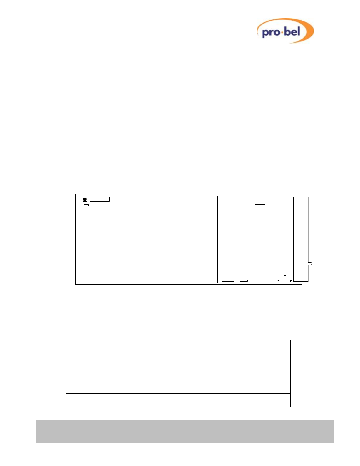
This figure shows the construction of the PCB, along with some components of interest. Note that the
main I/O connector is in fact mounted on a daughter board, which is held down by two screws. The Down
and Cross Converters also have a large sub-board mounted on the centre of the board.
The main connector is a 220-way 2mm press-fit connector. When new there may be a substantial
insertion force when mating with a rear module; this is normal. However, it is important that the module is
not plugged into one of Vistek’s conventional units with significant force. If so then it is possible to break
off one of the locating lugs.
2.6.2 Links and Switches
The purposes of the links and switches are shown in the following table. Details of their operation are
described in later sections.
ITEM Title Comments
SW1 RESET Used to reset the internal microcontroller.
JP1 Debug For development and test use only. (May not be
fitted)
JP2 H8 Program For development and test use only. (May not be
fitted)
PL1 JTAG Port Never used in operation. (May not be fitted)
JP3 JTAG Enable For Test. Fit in 2-3 position.
SW Video REF Term Slider up – Terminated with 75Ω
Slider down – Hi-Z (un-terminated)
PL1
JP3
JP2
JP1
SW1
Flash Memory Card
Front Panel
I/O Daughter Board
Rear Connector
FS1
SW
Video Processing Daughter Board
(V6404, V6406, V6408, V6418)
Page 22

V6402, V6404, V6406,V6408
and V6418 HD converters
22 Issue 6
2.6.3 Fuse
There is only one fuse on these modules, which is in series with the main DC input.
FS1 Fuse 2 Amp Wire
ended
In series with the +15V input to the module on the I/O
daughter board.
2.6.4 Flash Memory Card
The Flash Memory Card stores the firmware for the Microcontroller and the FPGA and is essential for the
operation of the module. If this card is missing, the front panel display will come up with an error message
(ERROR 10). The Flash Memory Card sits in a socket with a location peg to the right. In case of a
firmware upgrade, one has to make sure that the replaced card sits firmly and straight in the socket with
the location peg mating with the positioning hole on the baseboard.
The Flash Memory Card is re-programmable. Customers are kindly asked not to throw it away after
having upgraded a module with a newer firmware version. A Vistek service technician will collect it on
his/her next visit or it can be put in an envelope and sent back to the postal address shown on the cover of
this manual.
Flash Memory Card
(Side view)
Socket (Top view)
Location peg
Positioning hole
Page 23
V6402, V6404, V6406, V6408
and V6418 HD converters
HU-V6402&4&6&8&18 23
2.7 Front Panel
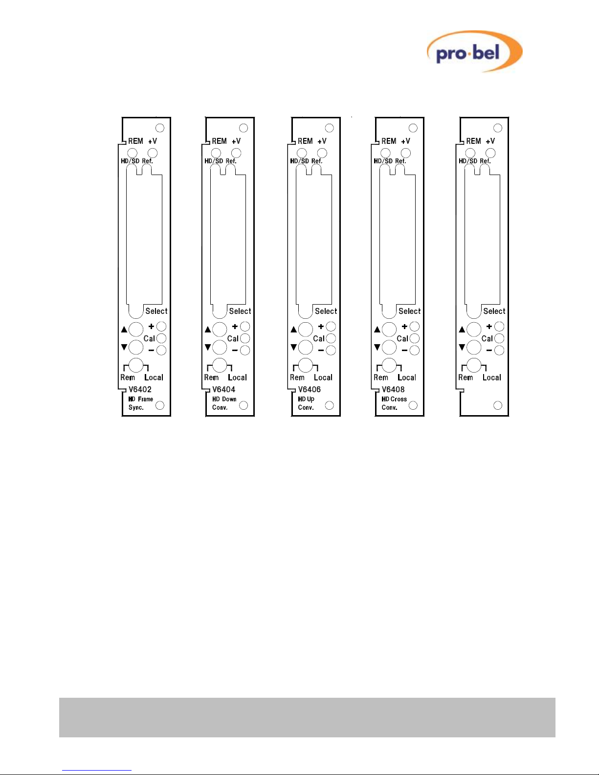
The front panels are similar to other complex V1600 types. They provide the user with total control and
monitoring of the unit without the need to consult manuals and read unlabelled indicators.
At first use the menu system may seem cumbersome but with only a small amount of practice it will
become very easy to use.
2.7.1 Direct Indications
The four LEDs at the top of the panel provide these direct indications of the unit:
REM
Short blinks to indicate access by the DART controller, if fitted. It does not directly
indicate that the unit is in remote control mode. If the rack frame does not have a
Rack Controller fitted then this LED will not blink.
+V Indicates that the main +3.3V is present on the board. This is derived from the
+15V distributed through the rack. The modules do have many power rails, but only
the main +3.3V is indicated here. It will, of course, be off if the fuse, FS1, were to
have been blown.
HD/SD Indicates that a valid SDI signal (either HD or SD) is being received.
REF Indicates that a video reference signal is being present – either bi-level or tri-level.
V6418
HD Conv.
U-D-X
Page 24

V6402, V6404, V6406,V6408
and V6418 HD converters
24 Issue 6
2.7.2 Display and Switches
The main display is an eight character LED matrix display. It has been set so that when fitted into a 3U
rack (V1606) it can be read from the left, and when fitted into a '1-Box' (V6011) it is horizontal and the
‘proper’ way up. (At time of writing it is not possible to fit the V64xx HD products into the V1602 1U rack!)
The three action buttons are labelled Select, ▲ and ▼. The Select button is used to move down and up
the menus. A short press will move down one level, while pressing and holding for about half a second
will move up one level. If you continue to hold it will progressively move up a level every half second until
it reaches the top level (SLEEP), or you let go, in which case it will stay where it is. When at any level the
▲ and ▼ buttons will move through the list of options, or if in an actual variable (such as Video Gain)
they will change the values.
If the unit is in Local control then the display and switches are used to set up and show the operation the
module. If in remote mode then they are still active for showing the status but cannot be used to actually
change anything.
Beside the ▲ and ▼ buttons are three LEDs marked +, CAL and –. In general the CAL LED is used to
show that a variable is set to its normalised value and if not then the others show in which direction it has
been changed or that it is no longer on its CAL value.
2.7.3 Remote/Local Control
The lowest switch selects between Local control and Remote control over DART:
Local Control is from the front panel itself.
Rem Control is from the DART system. This requires the use of an external
controller running a suitable programme, which communicates with multiple
racks using the Dartnet protocol.
Page 25

V6402, V6404, V6406, V6408
and V6418 HD converters
HU-V6402&4&6&8&18 25
3 SYSTEM OPERATION
3.1 Local Control
3.1.1 Start up
Local control and monitoring of the modules is done through the front panel with its eight character LED
display and three control buttons Select, ▲ and ▼. There are three LEDs which also contribute to the
status indication; these are labelled +, Cal and –.
After power up and having successfully passed the power-on-self test, the display will start at the top level
and show the unit type and any options that are included. The display will be one of these:
Unit type Password protected Option(s)
Other options
V6402 VP, FD
V6404 VP, SY, SV, FD, AH
CP
V6406 VP, SY, SV, FD, AH
CP
V6408 VP, SY, SV, FD, AH
CP
V6418 VP, SY, SV, FD, AH
CP
If the last character shown is a '+' (e.g. V6404SV+), this indicates that the unit has further options installed.
To see what they are, use the ▼ button to navigate.
3.1.2 Option Abbreviations
Options are indicated by abbreviations. The following list illustrates their meanings:
Option Meaning
VP
Video Proc Amp
SY
Frame Synchroniser (inherent on V6402)
SV
Frame Synchroniser + Video Proc Amp
FD
Field/Frame Delay (requires either SY or SV option)
AH
Audio Handling
CP
Closed Captioning
Page 26

V6402, V6404, V6406,V6408
and V6418 HD converters
26 Issue 6
3.1.3 Menu Control
The Select, ▲ and ▼ buttons are used to manoeuvre around the menu system. The menu structure has
five levels and the Select button is used to go up and down the structure. The ▲ and ▼ buttons are used
to move between selections or to adjust a parameter depending on which sort of menu is displayed. The
five levels are as follows:
Sleep Display is blank (except for Banner warnings).
Top Level
As above, e.g. V6402FD
Main Menu The Main menu items, such as VIDEO, STATUS, ENG’ING etc. These
items are all in Upper Case.
Sub Menu Menu items under each main heading, such as Source or A/R under the
VIDEO main menu. These items are all in Sentence Case (generally
lower case but with upper case first letters).
Parameter The lowest level under the Sub Menu, and used to actually adjust a
parameter. The display will depend on the actual parameter and may be
a value such as +0.00dB for a gain or ON or OFF for a switch variable.
There is usually a title to describe the variable and a small icon in the left
hand character position, but 8 characters cannot provide for a detailed
description.
To move down a level just press the Select button briefly; then press either the Select button again to go
down another level or the ▲ and ▼ buttons to move around the options within a level.
To move up a level press and hold the Select button for about half a second which will move up one level.
If you continue to hold the Select button then it will move up a level every half a second until it reaches
the Sleep level (one above the Top Level).
A complete list of all the menus is given in Section 5.
Page 27

V6402, V6404, V6406, V6408
and V6418 HD converters
HU-V6402&4&6&8&18 27
3.1.4 Menu Examples
This section has examples of how to manoeuvre through the menu system. The first one starts with the
unit in its ‘sleep’ mode where the display is blank, and then proceeds to set the reference source to the
processing input (Vid I/P).
Action Display Comments
Select
V6404SV
Top Level
Select
VIDEO
The Main Menu we want
Select
Source
The first Sub Menu in the list
▼
A/R
▼
Ref Src
The Sub Menu we want
Select
Auto
The default setting
▲
Vid I/P
Set it as we want it
Now we shall select how the unit behaves when the input fails. The following steps should be taken from
the current position (Select+Hold means that you should press and hold the select button for about half a
second):
Action Display Comments
Select+Hold
Ref Src
UP to the Sub Menu level
▼
Anc Data
▼
VFL Mode
The Sub Menu we want
Select
Black
The default setting
▲+ Hold
1 sec
Unit automatically counts up till it comes
to…
Freeze
or do you want it to go 'Black' after 14 sec?
▼
14 sec
Set it as we want it
3.1.5 Sleep
If the front panel is not used for a certain amount of time then the display will automatically go into a sleep
mode when it will be blank. Pressing any of the buttons will cause it to ‘wake up’ back into the top level.
The time delay before the unit slips into sleep mode can be set up using the ENG’ING : Sleep menu.
The brightness of the display can also be adjusted using the ENG’ING : LEDLevel menu.
Page 28

V6402, V6404, V6406,V6408
and V6418 HD converters
28 Issue 6
3.2 Common Features to all Units
3.2.1 SDI Inputs
The SDI inputs must conform to either the SMPTE292M or SMPTE259M standards, which describe the Bit
Serial Digital Interface for HD and SD operation. If only one input is required then it should be connected
to SDI 1. Unused inputs can be left open, it is however recommended to terminate unused inputs with a
75Ω Terminator to improve noise immunity. Signals of different frame-rates, resolutions or even a mixture
of SD and HD standards can be connected to both Inputs at the same time, however only one of the two
inputs can be selected at a time. Note that switching between different standards is neither instant nor
glitch-free. This has to do with the necessity of the SDI de-serialiser hardware to lock to the newly
detected standard. Furthermore, in case of an SD-to-HD switch over (or vice versa), the FPGA on the
baseboard must be re-loaded. This process takes about 2 to 3 seconds.
The input selection is done on the VIDEO : Source menu.
3.2.2 SDI Reclocked & Buffered Output
This is always available, and is a reclocked version of either SDI 1 or SDI 2, depending on the source
selection. It is an unprocessed signal, i.e. neither synchronised nor converted.
3.2.3 SDI Main Outputs
The main synchronised/processed SDI output is available on two BNCs.
3.2.4 Video Reference
The external video reference is available for units with the Frame Synchroniser function; it can be either a
standard composite black and burst video signal, or a new style tri-level sync. The unit will automatically
detect which and extract the relevant timing information.
Note that on V6404, V6406, V6408 and V6418 units the SY function is optional. If it is not enabled, the
Video Reference Input has no function.
The reference is looped on the rear module so it can be daisy chained along several modules. For
accurate timing, this is not recommended. There is a termination on the I/O daughter module, which can
be switched in at the end of the chain. Care should be taken to ensure that each reference has only one
termination set.
The units can operate from either the external reference or use the selected SDI input. This is selected on
the VIDEO : Ref Src menu. When set to Auto, the external reference will be used if available; otherwise
the selected SDI input will be used as the reference.
3.2.5 Standard Detection
The units detect and report back the detected video standard and frame-rate of the selected SDI input and
that of the reference input. The detected standard can be seen in the STATUS menu under I/P Std and
Ref Std.
V6406
V6408
V6418
V6404
V6402
Page 29

V6402, V6404, V6406, V6408
and V6418 HD converters
HU-V6402&4&6&8&18 29
3.2.6 TRS Signals
The TRS signals are the digital equivalent of the analogue synchronising pulses. All modules described in
this manual always regenerate the TRS signals on their output, so that any errors on the input signal will
not be propagated through.
3.2.7 EDH (SD operation only)
EDH is a method of embedding data within the ancillary data space that carries a measurement of the
integrity of video and other data. By regenerating the equivalent measurement at the receiving end it is
possible to check that the data has been received correctly.
HD signals always have the EDH data in form of checksums embedded, but for SD signals it is optional.
On the V6404 Down Converter or V6418 Converter, the EDH on the output can be disabled on the
ENG’ING : O/P EDH menu. Care must be taken if the new EDH generation is disabled and the old EDH is
being passed through because it will probably not correctly represent the data. In this case the Ancillary
Data really ought to be blanked.
3.2.8 Illegal Codes
A function of these modules is to ensure that the SDI output always meets the relevant specification. In
particular this means that the output is always legal in the sense of Line Length, Field Length and data
values. In the main this works extremely well, but there are some circumstances where it fails:
1. If the output timing is being changed, there will be momentary errors.
2. If the input is noisy, such that erroneous data is received, then the ancillary data may get checksum
errors. This obviously only applies if the Ancillary data is being passed. The video will be all right,
since the EDH (SD operation), respectively the line numbers and CRC codes in accordance with
SMPTE 292M (HD operation) are regenerated on the output.
3. If the reference is unstable or changing standards then the output will not be stable.
3.2.9 Horizontal and Vertical Blanking Interval Data (HANC and VANC)
V6402 and V6404/V6406/V6408/V6418 with SY option:
Any data embedded in the horizontal and vertical blanking intervals can be retained throughout the Frame
Synchroniser stage. Ancillary Data can be passed unchanged (VIDEO : Anc Data ð Anc Pass) or it can
be set to 'Black' (VIDEO : Anc Data ð Anc Blnk).
V6404/V6406/V6408/V6418 (with or without SY option):
Provided that the Down- or Cross-Converter unit is fitted with the Audio Handling (AH) option or the
Closed Captioning option (CP), relevant chunks of Ancillary data, such as embedded Audio or Closed
Captioning, can be transferred from the Input standard to the selected Output standard.
Page 30

V6402, V6404, V6406,V6408
and V6418 HD converters
30 Issue 6
3.2.10 SDI Input Fail
V6402 and V6404/V6406/V6408/V6418 with SY option:
If the selected SDI input fails, then the output picture will be either frozen, set to black or the selected input
will switch from input 1 to input 2 (VIDEO : VFL Mode). If the Frame Delay option is not installed or set to
zero, the output will resume after a full frame of undisrupted video has been received. On units with the
Frame Delay option installed, resumption of the 'live' output will be delayed by the number of Frames set
in the VIDEO : F Delay menu.
V6404/V6406/V6408/V6418 without SY option:
If the selected SDI input fails, then the output picture will be frozen. The output will continue after a full
frame of video has been received.
V6418 in Short Delay Down Conversion mode:
When the V6418 is operating in Short Delay Down Conversion mode (ENG’ING : DownConv
: ShortDel), if the selected SDI input fails, then the output will be set to black. The output will continue
after a full frame of video has been received.
3.2.11 Video Reference Fail
V6402 and V6404/V6406/V6408/V6418 with SY option:
When there is no external reference signal present, the unit will use the selected SDI input as its timing
reference if VIDEO : Ref Src is set to Auto. If VIDEO : Ref Src is set to Ref I/P, the module continues
operating in a free-run mode if the external reference is invalid or absent.
Under the circumstances described above and depending on the setting of VIDEO : RFL Mode (Reference
Fail Mode), the module then switches automatically into a minimum delay mode (Min Dly) or it maintains
the delay set by the F-, V- and H- Delay controls (Adj Dly).
A module can be also forced to use the SDI input as its timing reference by setting VIDEO : Ref Src to
Vid I/P. In this case, the current setting in VIDEO : RFL Mode will be ignored and the total insertion delay
simply depends on the current settings in the F-, V- and H- Delay controls.
3.2.12 GPI Configuration
The modules have one GPI available at the rear with a BNC connection.
Connecting the input to 0v activates the GPI, leaving it open circuit de-activates it. The status is shown in
the STATUS : GPI menu as GPI ↑ or GPI ↓, the former being active and the latter inactive (despite the
fact that connecting it to 0v makes it active).
The GPI function can be set-up in the CONFIG : GPI menu to control the input selection, or switch the
module’s output to 75% bars generated internally. The 75% bars output option will only function with the
SY option fitted.
Note that, if Video fail mode is set to “switch to I/P 2”, the GPI can be used to set the source back to I/P 1
after the signal is restored. If the GPI is set to SDI1, it can be activated either permanently or
momentarily. If it is set to SDI2, a momentary activation resets the source back to I/P 1.
Page 31
V6402, V6404, V6406, V6408
and V6418 HD converters
HU-V6402&4&6&8&18 31
3.2.13 Video Reference Mismatch
When a mismatch between the Video Input's (Vid I/P) frame-rate and the Reference's frame-rate is being
detected, the output can either follow the Vid I/P or the Reference, depending on the setting of
VIDEO : XStdMode (also known as 'Cross-Reference' mode).
Available options are:
XStd Ref: Output frame-rate is set to Reference frame-rate, no matter what the Video Input
frame-rate is.
XStd I/P: Output frame-rate is set to Video Input frame-rate
V6402 Example: Vid I/P is 720p @ 59.94Hz
XStdMode is set to XStd Ref
Ext. Reference changes from 59.94Hz to 50Hz
ð Output frame-rate instantly changes to the Reference frame-rate, i.e. the Output standard will be 720p
@ 50Hz thereafter. The Output picture will look somehow corrupted - which is absolutely normal - but the
Output video timing fully complies with the 720p50 standard. The reader should be reminded here that no
member of the V64xx Series can perform frame-rate conversions (e.g. 59.94Hz to 50Hz).
The Frame Synchronizer will automatically resume normal operation as soon as a frame-rate match has
been re-established.
3.2.14 Delay Signal
The Frame Synchroniser produces a signal that represents the variable delay being inserted into the video
path. This delay information is passed on internally to the V6302 Advanced Audio Processor (if present)
and used to provide a tracking delay to the audio. The signal is also available externally so it can be used
by other audio tracking devices. Please note that the length of the tracking delay pulse is a measure for
the variable delay between input and output only – it does not cover for any additional Field/Frame-Delay
added on top of the variable delay.
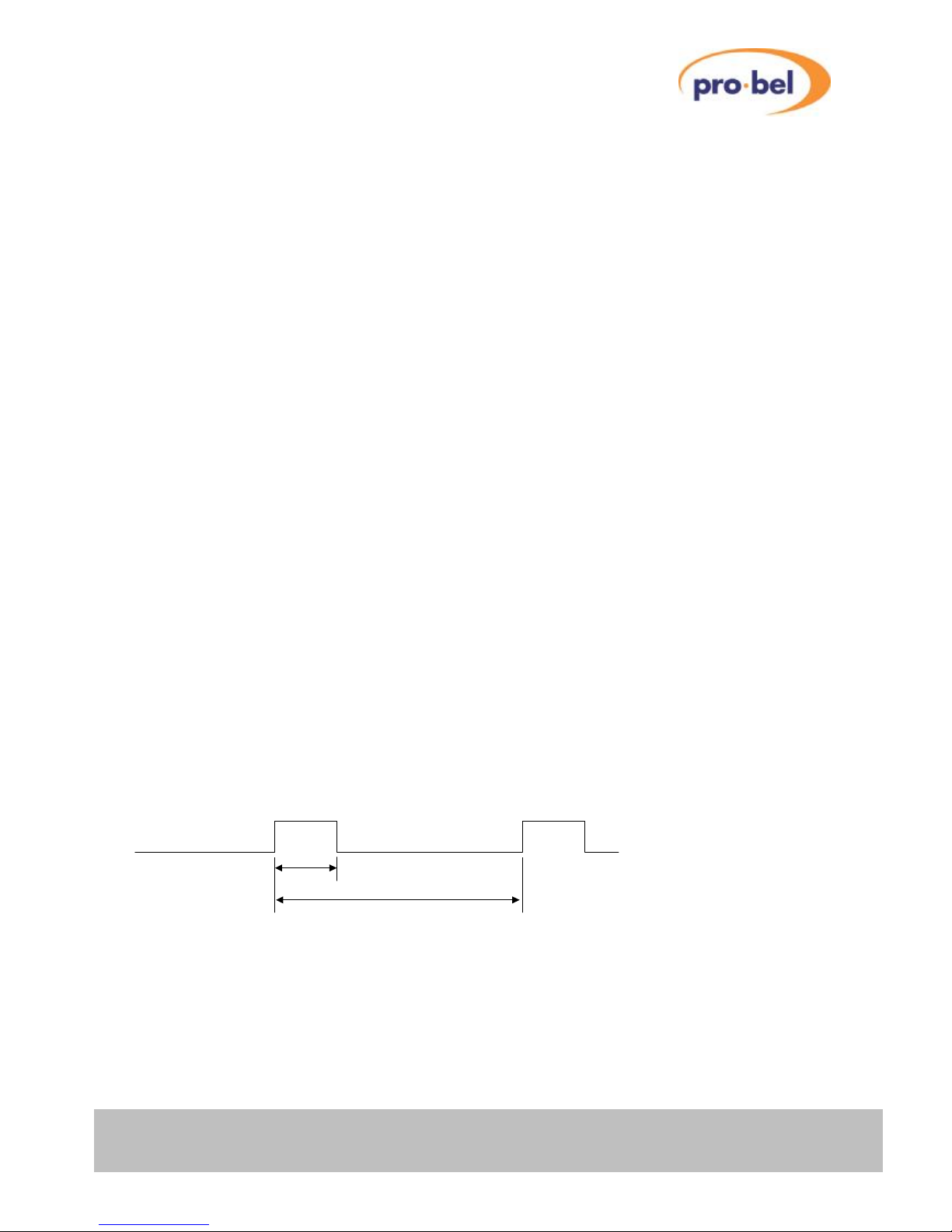
The Delay signal has repetition rate of two frames and the positive pulse width represents the variable
delay. This is shown in this diagram.
2 Frames
Delay
If the unit is not synchronising, such as loss of I/P or Freeze, then the delay output is blanked (static low).
It is expected under these conditions that the audio processing will hold its current delay from the last valid
measurement until a pulse re-appears.
The external Delay Pulse output is available on a BNC on the rear panel. The external pulse itself is
nominally 3.3V with a sourcing/sinking capability of ±24mA.
Page 32

V6402, V6404, V6406,V6408
and V6418 HD converters
32 Issue 6
3.2.15 VCO Centre Frequency
Normally, the output is locked to the video reference - if present - and of the same standard as the video,
or to the input video itself. If there is no signal or reference connected then the output will free run at the
nominal centre frequency of the on board clock generator. This centre frequency can be adjusted under
the CALIB : CntrFreq menu, but this should not normally be necessary in the field.
It is possible to force the unit into its free-run mode using the ENG’ING : Free-run menu. This is an
unusual requirement and so is a setting that appears on the top level banner when set.
3.2.16 Version Numbers
Each module comprises various items of software/hardware and they all have separate version numbers.
These can be read on the following read only menus:
STATUS Soft Ver XX.XX.XX
Microprocessor Code
STATUS FPGA Ver XX.XX
FPGA Code
STATUS CPLD Ver XX.XX
CPLD Code
STATUS PCB Ver XX.XX
The PCB revision, with Mod status
STATUS Boot Ver XX.XX.XX
Boot Loader
3.2.17 Memory Size
The amount of SDRAM fitted on the baseboard can be checked in the read only menu
STATUS : Mem Size. Some module functions, such as the Field/Frame Delay option, are memory size
dependent. Currently, modules are available with two different memory configurations:
Memory Size Supported Features
24MBytes Basic – with limited Field/Frame Delay functionality
96MBytes Required for full Field/Frame Delay support
3.2.18 Display Sleep
Since, for the vast majority of its life, a module will operate behind the front panel of a rack frame, the
display on the local front panel will not be visible so it will go to sleep after a certain time. This timeout
delay can be changed on the ENG’ING : Sleep menu to be anything between 0 and 30 minutes; 0
minutes means that it will stay on indefinitely. The sleep timeout always counts from the last front panel
button push. The default time is 5 minutes.
The panel can also be forced into its sleep mode by moving up a level from the Top Level menu, which
displays the module type.
To get the display to come on again simply press one of the buttons and the menus will start again at the
Top Level.
3.2.19 Display Brightness
The brightness of the front panel display can be adjusted on the ENG’ING : LEDLevel menu.
ENG’ING LEDLevel ▓ ▓ ▓ ▓
Page 33
V6402, V6404, V6406, V6408
and V6418 HD converters
HU-V6402&4&6&8&18 33
3.3 Module Specific Functions
3.3.1 Manual Freeze
The output picture can be frozen manually using the VIDEO : Freeze menu.
With interlaced video input formats, such as 1080i59, the operator has the choice between
Field1 - Field2 - Frame. Please note that when freezing a field, the selected field will be used for
displaying both fields, resulting in a simple line-doubling effect. When freezing an interlaced input as
'Frame', the frozen image may appear very fuzzy or shaky, depending on the amount of motion between
field1 and field2.
With progressively scanned input formats, the same choices are available, but a Frame-Freeze actually
happens when selecting any of the three options (Field1 - Field2 - Frame).
When using the manual freeze function in connection with the Field/Frame Delay option, resumption of
normal operation after a freeze will be delayed by the same number of frames (or fields) as set in the FDelay menu.
The reason for that is that after having sent the Run command, the frame buffer must be filled first with nframes in order to maintain the delay as set in the F-Delay menu.
At HD operation, this 'resumption-delay' is almost not noticeable, even if the frame-delay is set to a
maximum. At SD operation however, the delay can be up to 2 seconds!
3.3.2 Timing & Delay Control
3.3.2.1 With External Reference (Ref I/P)
The delay imposed on the SDI data processed by a frame-synchronising module depends first of all on the
Reference Source selection. If an external, analog Reference signal (e.g. Bi- or Tri-Level Sync) is present
and the Ref Src selection control (VIDEO : Ref Src) is set to Auto, the V64xx will automatically operate
as a Frame-Synchroniser, which means that its output will be frame-synchronous to the Reference signal
applied.
In order to keep pace with the incoming SDI data, the Frame-Synchroniser will either repeat a frame or
drop a frame once in a while, depending on a) which of the two clock domains (Input Video versus
Reference signal) is the faster, and b) how far the two clock domains are apart (typically in the range of 0
to ± 150ppm).
Between the events of two successive frame repeats, respectively two frame drops, the input-to-output
delay will gradually increase (or decrease) from a variable minimum value (hysteresis) up to one frame (or
vice versa). Hysteresis is essential in order to prevent a series of frame drops or repeats when
approaching the 'roll-over' point.
As explained earlier, an extra n-field/frame delay can be introduced on top of this variable delay if the 'FD'
option is enabled.
When operating the V64xx as a Frame-Synchroniser, two timing controls (V- & H-Timing) are available for
adjusting the board's output timing relative to the external Reference signal. This works irrespective of the
additional Field/Frame delay, which can be applied on top of the inherent variable delay.
VIDEO : V Timing: Purpose: For vertical adjustment (in number of lines)
Range: -256..+255 lines
VIDEO : H Timing: Purpose: For horizontal adjustment (in microseconds)
Range: from 0µs up to (duration of one line – one pixel)
V6406SY
V6408SY
V6418SY
V6404SY
V6402
V6406SY
V6408SY
V6418SY
V6404SY
V6402
Page 34
V6402, V6404, V6406,V6408
and V6418 HD converters
34 Issue 6
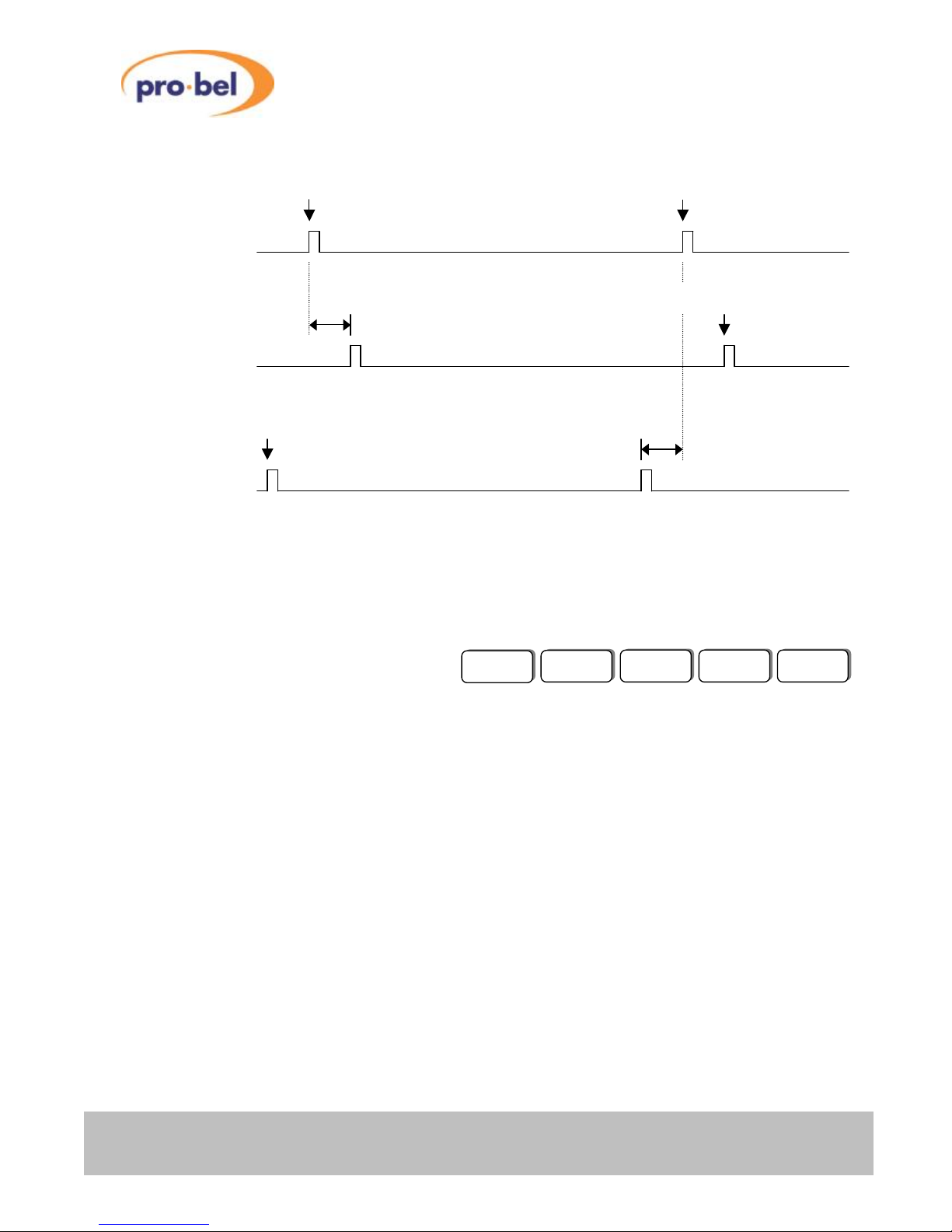
This drawing illustrates the Reference-to-Output timing relationship when operating a V64xx in its FrameSynchroniser mode.
Note that the Input-to-Output delay in a Frame-Synchroniser is variable and spans from a minimum delay
up to a complete Frame. This timing variation can be monitored with a scope on the Delay Pulse BNC.
3.3.2.2 With Internal Reference (Vid I/P)
Alternatively, the V64xx can be used as a straightforward, adjustable Field/Frame Delay module, in
applications where for example the incoming SDI signal is already frame-synchronous but requires an
arbitrary delay in order to compensate latency accompanied with the encoding of specific Audio formats.
Disconnecting the external Reference signal (in case VIDEO : Ref Src is set to Auto) or forcing the unit to
take its Video Input as the Reference signal (VIDEO : Ref Src is set to Vid I/P) will automatically disable
the Frame Synchroniser function and put the board into a pure delay mode.
The V- and H-Timing controls change their meanings into V- and H-Delay. If the F-Delay option is
enabled, an extra n-Field(s)/Frame(s) delay can be imposed on top of the V- and H-Delay.
F
Important:
If VIDEO : Ref Src is set to Auto and no external Reference signal is present, the unit assumes that there
is a persistent problem with the external Reference and the actual insertion delay is controlled by the
setting in the VIDEO : RFL Mode menu:
If RFL Mode is set to Min Dly, all delay control settings will be forced to zero and the unit continues
operating in a minimum delay (= intrinsic delay) mode.
If RFL Mode is set to Adj Dly, the insertion delay is the sum of the unit’s intrinsic delay plus whatever is set
in the F-, V- and H-Delay controls.
Start of new Frame Start of new Frame
Ext. Reference
Output is 'delayed' relative to the external Reference
signal by V-Timing + H-Timing
Start of new Frame
V6402 Output
with positive
V-Timing
Output is 'advanced' relative to the external Reference
signal by V-Timing + H-Timing
Start of new Frame
V6402 Output
with negative
V-Timing
V6406SY
V6408SY
V6418SY
V6404SY
V6402
Page 35
V6402, V6404, V6406, V6408
and V6418 HD converters
HU-V6402&4&6&8&18 35
VIDEO : F Delay: Purpose: Coarse delay (in number of fields or frames)
(Password enabled Option) Range: depends on baseboard configuration and
Input Standard
VIDEO : V Delay: Purpose: Fine delay (in number of lines)
Range: 0 up to (number of total lines per field/frame – one line)
VIDEO : H Delay: Purpose: Super fine delay (in microseconds)
Range: 0µs up to (duration of one line – one pixel)
3.3.2.3 Field/Frame Delay (FD) Option
To check whether a module is fitted with the 'FD' option, go into the STATUS menu and see under Option
what options are fitted. If 'FD' is shown (might be shown together with other installed options), the board
can be used as an adjustable Field/Frame Delay.
In addition to the variable delay, which is inherent when operating as a Frame Synchroniser, an extra nFrame(s) (progressive input) or n-Field(s) (interlaced input) delay can be added on top of the variable
delay.
When operating the module without an external reference, an extra n-Field(s)/Frame(s) delay can be
added on top of the adjustable V- and H-Delay (see previous section for details).
The maximum amount of extra delay depends on the Baseboard’s frame store size (24MB or 96MB) and
the current Input Standard. To find out how much memory is fitted on the Baseboard, go into the STATUS
menu and check under Mem Size.
The two available Baseboard configurations are: 24MBytes or 96MBytes.
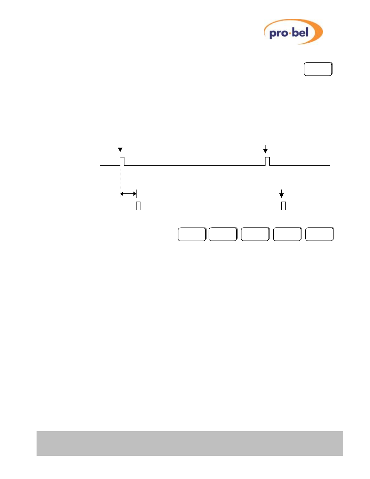
Start of new Frame
Start of new Frame
Video I/P
Output is 'delayed' by F-Delay + V-Delay + H-Delay
Start of new Frame
V6402 Output
FD V6406FD
V6408FD
V6418FD
V6404FD
V6402FD
Page 36
V6402, V6404, V6406,V6408
and V6418 HD converters
36 Issue 6
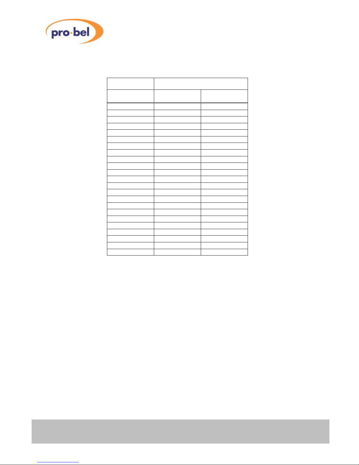
The following table shows the upper limits of the Field/Frame Delay control (VIDEO : F-Delay). Please
note that the actual numbers displayed in the menu F-Delay represent ‘Fields’ if the input standard is
interlaced and ‘Frames’ if the input standard is progressive:
Input Standard Maximum Delay
2
24MB Frame
store
96MB Frame
store
1080i60 4 fields 24 fields
1080i59 4 fields 24 fields
1080i50 2 fields 20 fields
1080p30 2 frames 12 frames
1080p29 2 frames 12 frames
1080p25 1 frame 10 frames
1080p24 1 frame 9 frames
1080p23 1 frame 9 frames
1080sf24 2 fields 18 fields
1080sf23 2 fields 18 fields
720p60 5 frames 25 frames
720p59 5 frames 25 frames
720p50 4 frames 21 frames
720p30 2 frames 12 frames
720p29 2 frames 12 frames
720p25 1 frame 10 frames
720p24 1 frame 9 frames
720p23 1 frame 9 frames
1035i60 4 fields 24 fields
1035i59 4 fields 24 fields
525i59 34 fields 68 fields1
625i50 28 fields 58 fields1
Note 1: An extra fixed delay of 1 second can be added on top of the 50/60 fields by setting the DELAY
option in the ENG’ING menu to ‘1 Second’. This option is only available if the Baseboard is fitted with
96MBytes of memory.
Note 2: The Maximum Delay values specified in this table apply for video delay only, if the FD option is
used in conjunction with the AH (Audio Handling) option, the following rules apply:
96MB FrameStore: In order to maintain the timing relationship between video and embedded audio, the
maximum Field/Frame delay numbers listed are reduced by 2 in the case of the V6404/08/18, and by 6 in
the case of the V6406.
24MB Frame Store: Audio delay compensation is not supported on 24MB boards.
In terms of the actual delay imposed, same numbers imply the same delay in milliseconds, provided that
the field/frame rate is the same. Example:
Input Std. is 720p59, F-Delay is set to 4 (frames): Output is delayed by 66.7ms (+ V-Delay + H-Delay)
Input Std. is 1080i59, F-Delay is set to 4 (fields): Output is delayed by 66.7ms (+ V-Delay + H-Delay)
Page 37
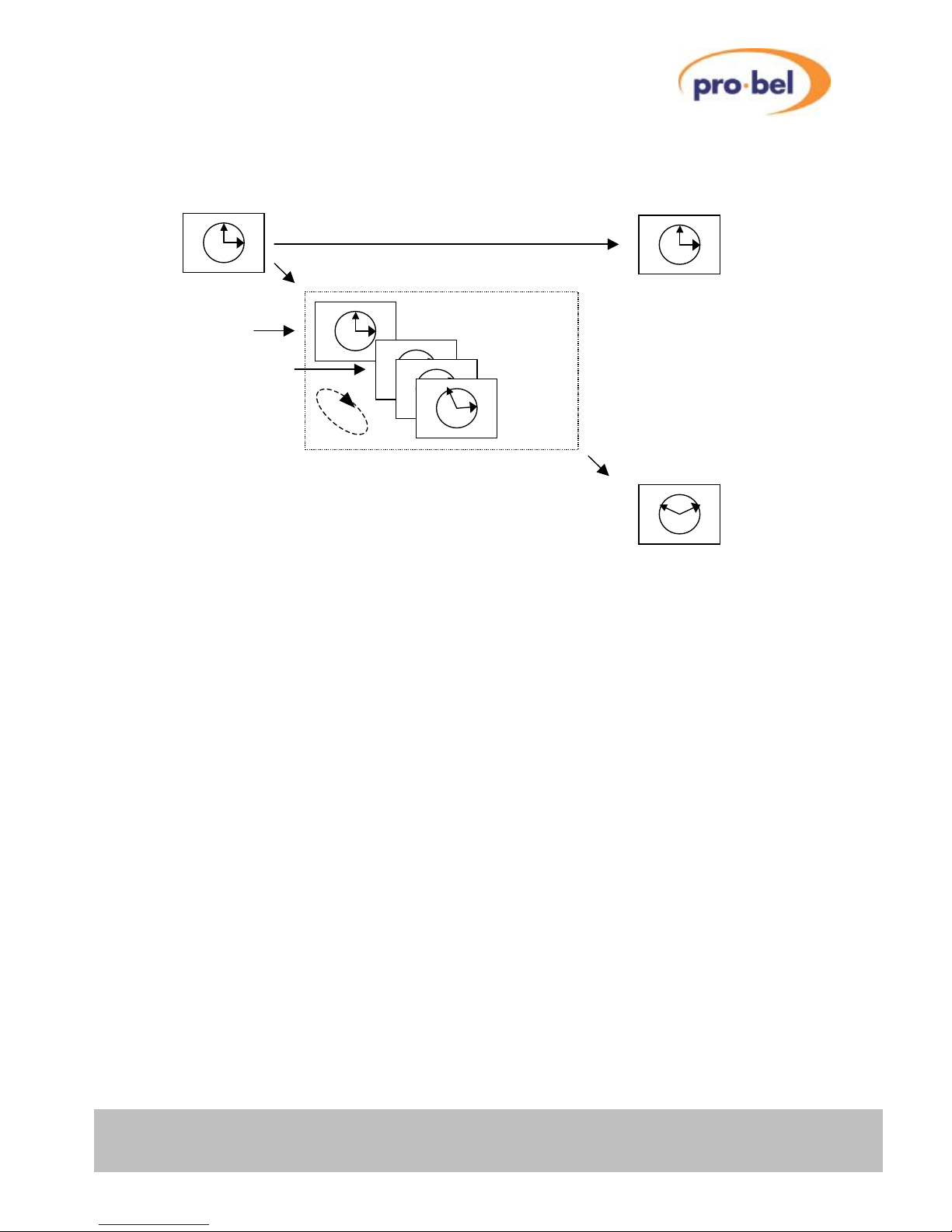
V6402, V6404, V6406, V6408
and V6418 HD converters
HU-V6402&4&6&8&18 37
The following illustration shows how the Field/Frame Delay works:
Live Video data gets written into a circular buffer (Frame-Store), which is n+1 frames deep (n is the
number of frames the output gets delayed on top of the variable delay). The buffer's write-pointer lags
exactly one frame behind the buffer's read pointer, which means that a frame that got written n-frames
ago, will be read one frame prior to it gets overwritten by a new frame.
If the input standard is interlaced, the output can be delayed on a ‘per-field’ basis by shifting the output
timing by one field (field1). The field order will remain intact.
Reclocked Output
Live Video Input
Processed Output Circular Buffer stores multiple Frames
scene that happened
n-Frames ago
current scene
Frame n
-3
Frame n
-2
Frame n
Frame n
-1
Current Write Pointer
Current Read Pointer
Page 38

V6402, V6404, V6406,V6408
and V6418 HD converters
38 Issue 6
3.3.3 Test Pattern Generator (TPG)
The V6402 and the V6404/06/08/18 with the SY option fitted come with a built-in Test Pattern Generator
(TPG). The test patterns can be used to provide signals for system testing and even for testing other
pieces of equipment. All test patterns are generated 'on-the-fly' and do not interfere with the current
contents of the Frame Buffer. Clean switching between test patterns and the selected live video input is
also provided.
On a V6402, the test patterns are being generated on the 'Output' side. It also means that they cannot be
used as an internal confidence signal for proving the correct operation of the V6402 itself.
On the V6404/06/08/18, test patterns are being generated on the 'Input' side to the filtering and scaling
processor, which means that they can be used to verify the conversion process.
The vertical interval is considered to be a part of the test pattern and is always synthesised as Black. This
means that the vertical blanking interval is always blanked when Test Patterns have been selected. The
same applies to Ancillary Data in the horizontal blanking interval.
The actual TPG selection menu can be found in the 'Engineering' Menu (ENG'ING : Test Ptn):
The default setting in the Test Ptn sub-menu is: TPG Off
From the remote control system they can be called up directly.
From here you have a choice of up to 7 built-in test patterns. Test pattern No.7 is a 'reserved' or a custom
Test Pattern and might change between different firmware versions. At the time of printing, it is set to
'Black'. Note that the 100% and 75% colour bars have limited transition rates between adjacent bars.
V6406SY
V6408SY
V6418SY
V6404SY
V6402
Page 39
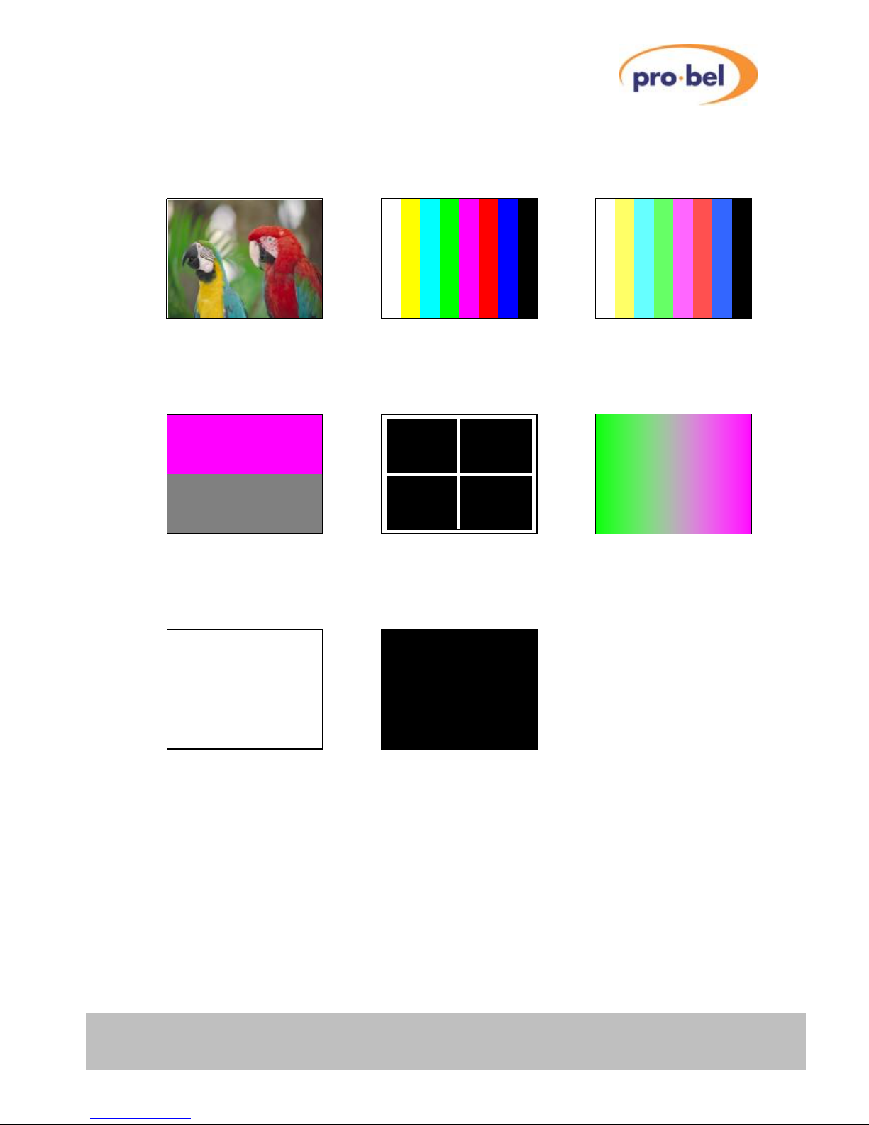
V6402, V6404, V6406, V6408
and V6418 HD converters
HU-V6402&4&6&8&18 39
Stepping through the menu, the following Test Patterns will be generated:
100 % Bars 75 % Bars
SDI Matrix
(Pathological signal)
Flat White
Cross Hair
(Timing)
►
► ► ► ►
TPG Off (Live Video)
►
►
Custom
('Black' at the time of
printing)
Linear Ramp
Page 40

V6402, V6404, V6406,V6408
and V6418 HD converters
40 Issue 6
The V6402 can be used as a simple stand-alone TPG, without the need for an Input signal or Reference
signal being present. If the module powers up without an Input signal present, its output will automatically
switch to the SD or HD Standard according to the selection made in the CONFIG : Def Std menu.
The Output Standard can be changed 'on-the-fly' by stepping through the Def Std menu. The Output
Standard will instantly change to the selected mode without changing the selected test pattern. Please
note that some Broadcast- or Professional-Monitors cannot cope with progressive standards with framerates of less than 50Hz, i.e. it is not surprising if no picture appears on the Monitor when selecting the
1080p25Hz or 1080p29Hz mode for example. A Waveform Monitor, such as Tektronix's WFM700 can be
used instead for monitoring these standards.
As soon as a valid Video Input signal is present, the output will follow the detected Input Standard. The
Output Standard can no longer be changed by flicking through the Def Std menu thereafter. Even when
the Input signal gets disconnected, the Output will remain in the 'last known good' mode. However, it can
be overwritten by changing to a different Input Standard. Only a Hardware Reset (or re-powering the
module) brings the Output Standard back to the Default Standard selected in the Def Std menu,
provided that no Input signal is present at the time of carrying out a manual Reset or re-powering the
module.
If a test pattern is selected (ENG'ING : Test Ptn : Bars 100 etc.) and the unit gets switch off, it will
reboot next time with this last selected Test Pattern and the last selected Default Standard.
Page 41
V6402, V6404, V6406, V6408
and V6418 HD converters
HU-V6402&4&6&8&18 41
3.3.4 Conversion Modes
Input Modes:
By default, an auto-sensing mechanism switches the board between SD or HD input modes, depending on
the Input standard applied to the board and the selected output standard.
Alternatively, the board can be 'forced' to work either in SD or HD input modes. In order to do this, go into
the CONFIG : SD/HD Op menu. The three available options are: Auto, HD and SD:
'Auto', as the name implies, enables the auto-sensing mode. Changing the Input Standard from 525i59 to
720p59 for example will prompt the Microcontroller to re-load the FPGA automatically.
'HD' will force the board to permanent HD input operation.
'SD' will force the board to permanent SD input operation.
Permanent SD or HD operation might prove to be useful in installations where:
the infrastructure is fixed to SD or HD anyway
operation in 'noisy' environments
a lot of Input Standard switching is going on (within one group of Standards)
Forcing the board's operational mode to either SD or HD will prevent it from unintentionally re-loading its
FPGA code due to false interpretation of the detected Input Standard.
Output Modes:
In addition to forcing the input standard detection to a specific standard the conversion can be put into
these two modes via the CONFIG:OP Mode.
‘Normal’ applies the necessary conversion to maintain the selected output standard.
‘Up/Down’ automatically up converts to the selected HD output standard when the input is SD, and down
converts a HD input to SD, either 525 or 625 depending on the frame rate of the HD input.
V6418
V6408
V6404
V6402
V6418
Page 42
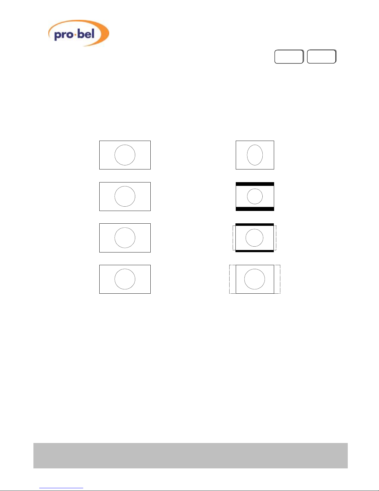
V6402, V6404, V6406,V6408
and V6418 HD converters
42 Issue 6
3.3.5 Down Converter Aspect Ratios
A Down-Converter always converts a 16:9 input picture to a 4:3 aspect ratio output. The V6404/18 gives
four options in the VIDEO : A/R menu (VIDEO : A/R Down for V6418). They are shown diagrammatically
below. Note that some conversion settings result in a loss of parts of the original picture (indicated by
hatched areas).
If the V6418 is set in Short Delay Down Conversion mode (ENG’ING : DownConv : ShortDel), only 4:3
Anamorphic and 4:3 Centre Cutout aspect ratios are available.
4:3 Anamorphic
16:9 Letter Box
14:9 Letter Box
4:3 Centre Cutout
16:9 Input 4:3 Output
V6418
V6404
Page 43
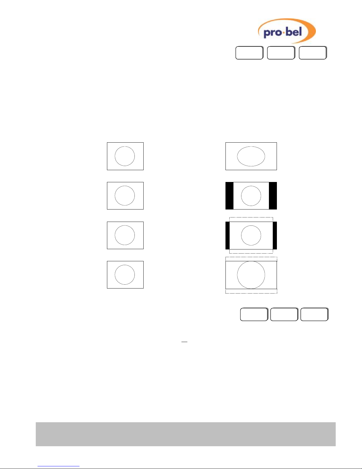
V6402, V6404, V6406, V6408
and V6418 HD converters
HU-V6402&4&6&8&18 43
3.3.6 Up/Cross Converter Aspect Ratios
Since all of the currently supported HD standards have the same 16:9 aspect ratio, there is no need to
perform an aspect ratio conversion when cross-converting between them.
If the V6406/08/18 is fed with an SD input, it will up-convert to the selected HD standard (provided they
have the same frame-rate). The input picture will be scaled appropriately in order to accommodate the
16:9 HD video format. There are four options in the VIDEO : A/R menu (VIDEO : A/R Up for V6418).
They are shown diagrammatically below. Note that some conversion settings result in a loss of parts of the
original picture (indicated by hatched areas).
3.3.7 Cross- & Up-Converter Output Standard Selection
The desired HD output standard must be set manually on the V6406 / V6408 / V6418. This can be done in
the menu VIDEO: O/P Std. Supported conversions are shown in section 1.3.
When stepping through the menu, the operator sees all implemented HD standards and not just frame-rate
matching modes, so one must be careful that the selected output standard matches with its frame-rate with
the input frame-rate for proper operation.
V6418
V6418
16:9 Anamorphic
4:3 Pillar Box
14:9 Pillar Box
16:9 Centre Cutout
4:3 Input 16:9 Output
V6408
V6408
V6406
V6406
Page 44

V6402, V6404, V6406,V6408
and V6418 HD converters
44 Issue 6
3.3.8 V6418 Short Delay Mode
The V6418 can be set in Short Delay Down Conversion mode in the menu: ENG’ING : DownConv
: ShortDel. This mode applies only when the V6418 operates as a HD to SD down converter or a SD to
SD bypass.
This is a limited feature operation mode, designed for monitoring purposes and not intended for
broadcasting. Its main characteristic is a reduced input to output delay, compared to the standard down
conversion or standard SD bypass modes. The image quality in the short delay down converter is slightly
lower than in the standard down converter. In the short delay SD bypass there is no quality loss compared
to the standard SD bypass.
When the short delay mode is selected, the input to output delay is < 1 ms for down conversion and < 10
us for SD bypass.
For down conversion, only 1080i50, 1080i59, 720p50 and 720p59 input standards are supported. In the
same way, only anamorphic and centre cutout aspect ratio conversions are implemented. In SD bypass
the aspect ratio cannot be changed.
For both short delay down conversion and short delay SD bypass modes, only Video Processor Amplifier
(VP), Audio Handling (AH) and Closed Caption (CP) options are available. In case of input video failure,
the output is switched to black.
Page 45

V6402, V6404, V6406, V6408
and V6418 HD converters
HU-V6402&4&6&8&18 45
3.4 Video Processing Amplifier
3.4.1 Video Gain
PROC AMP V Gain
The adjustment range is ±6dB and it applies equally to the luminance and both of the chrominance
channels (Cb and Cr). The gain is applied after the black level offset. The Video gain is applied
simultaneously with the Chrominance gain so they can cancel one another out. For example +3dB of
Video gain along with –3dB of Chroma gain will result in the luminance being increased by +3dB and the
Cb and Cr channels being unchanged.
The output is limited to ensure that there is no numerical overflow as the output fits into the 10 bit D1
domain. There is no gamut legalisation function.
3.4.2 Chroma Gain
PROC AMP C Gain
The adjustment range is ±6dB and it applies equally both the chrominance channels. The gain is applied
along with the video gain and after the black level offset. The Chrominance gain is applied simultaneously
with the Video gain so they can cancel one another out. For example +3dB of Video gain along with –3dB
of Chroma gain will result in the luminance being increased by +3dB and the Cb and Cr channels being
unchanged.
The output is limited to ensure that there is no numerical overflow as the output fits into the 10 bit D1
domain. There is no gamut legalisation function.
3.4.3 Black Level
PROC AMP Blk Lvl
The adjustment range is –127 and +128 D1 levels (equivalent to -101/+102mV). The black level
adjustment is applied before the gain stages. This is considered the best arrangement since the unit is
usually used to correct incoming errors.
3.4.4 Hue Shift
PROC AMP Hue
The adjustment range of the hue shift is ±45° in 0.35° steps.
3.4.5 Dynamic Rounding
PROC AMP Dyn Rnd
Since some quantising effects may be visible on the output of this unit when variable gains are applied,
Dynamic Rounding has been applied. This Dynamic Rounding is only used to reduce the effects of the
fractional bits of lower significance than the normal 10 bits; it does not reduce the resolution to 8 bits.
This can be disabled on the PROC AMP : Dyn Rnd menu.
V6406VP
V6408VP
V6418VP
V6404VP
V6402VP
Page 46

V6402, V6404, V6406,V6408
and V6418 HD converters
46 Issue 6
3.4.6 Limiting
PROC AMP Hrd Clip
Since gain can be applied to the D1 signal it is possible to generate levels outside the normal 10 bit gamut
of D1 and so limiting is required. The V64xx Proc Amp normally applies a soft form of limiting that
progressively reduces the gain of a signal as it approaches the limits, either overshoot or undershoot. If
this is not required then it can be disabled on the PROC AMP : Hrd Clip menu.
The limiting that is applied is ‘simple’ in that it does not ensure that the output is correctly within the colour
gamut, but only that each of the three components (Y, Cb, Cr) remains within the legal 10 bit range.
Certain test patterns, most notable the amplitude ramps, contain data that is within the overshoot and
undershoot areas. If they are passed through the Proc Amp with its default soft clipping then they will be
modified. This means that the EDH value on the output will be different to that on the input. If this is not
wanted then the Hard Clipping can be turned ON, but this is not recommended for normal Proc Amp
operation.
3.4.7 Fade to Black
PROC AMP Fade>Blk
V64xx modules with the VP option fitted include a fade to black facility. This enables the output to be
cleanly attenuated to digital black on receipt of an internal command.
The rate of the fade is fixed at half a second.
Locally the fade can be initiated on the PROC AMP : Fade>Blk menu. This contains both an ON and OFF
command.
The fade can also be initiated over the DART remote control network. The fade will start as soon as the
command is sent.
The output will stay at black until any active control input is released, or the unit is reset. There is no
direct indication on the front panel that the output is being forced to black except for the top level banner,
if enabled.
Page 47

V6402, V6404, V6406, V6408
and V6418 HD converters
HU-V6402&4&6&8&18 47
3.5 Audio Handling
The V6404/06/08/18 provide some functionality for dealing with embedded audio. These functions are
summed up in a group called 'AUDIO'.
The main task is to 'transfer' the embedded audio information between the different domains, i.e. from SD
to HD or vice versa, whilst preserving its original digital content.
Audio is de-embedded before video processing, then re-embedded afterwards. The audio delay is
automatically matched to the video processing delay to within 1ms.
3.5.1 Audio Group Selection
V6404/06/08 V6404 V6406/V6408
AUDIO Aud Grp1 20bit/24bit/Off On/Off
Aud Grp2 20bit/24bit/Off On/Off
Aud Grp3 20bit/24bit/Off On/Off
Aud Grp4 20bit/24bit/Off On/Off
V6418 V6418
AUDIO En Grp1 On/Off
En Grp2 On/Off
En Grp3 On/Off
En Grp4 On/Off
Grp1 Res 20bit/24bit
Grp2 Res 20bit/24bit
Grp3 Res 20bit/24bit
Grp4 Res 20bit/24bit
Audio groups can be switched ON and OFF, but not shuffled. Channels within a group remain unchanged
in their order. Locally the settings can be made on the AUDIO : Aud Grp# menu.
3.5.2 Audio Group Status
STATUS Aud Grps 1 (2,3,4) indicates Group is present
- indicates Group is absent
The presence/absence of Audio Groups can be checked in the STATUS : Aud Grps menu.
Please note that if the V6404/06/08/18 comes with the Frame Synchroniser option fitted, any ancillary data
will be blanked altogether if VIDEO : Anc Data is set to Anc Blnk.
V6408AH
V6418AH
V6406AH
V6404AH
Page 48
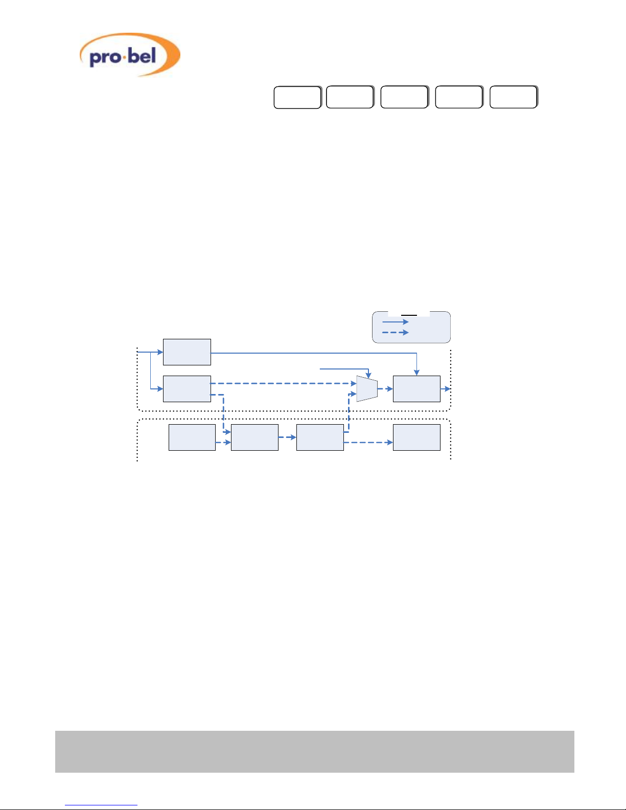
V6402, V6404, V6406,V6408
and V6418 HD converters
48 Issue 6
3.6 Audio Processing
The audio processing capabilities of the V6302/AP Advanced Audio Processor module can be utilised by
any of these modules by combining the V6302/AP module with the V64xx module in a V16HR3D Double
width or V16HR3E Triple width rear module. No Option needs to be set, just combining any of these
modules with a V6302/AP will automatically enable this functionality.
The V6302/AP has an all-digital Audio Processing Engine (APE) that provides synchronisation, gain,
routing, fixed and tracking delay functions on the inputs and is intended for application in both Standard
Definition and High Definition installations. It has six AES inputs and four AES outputs on the rear panel.
An optional Dolby Decoder submodule has Dolby E and Dolby Digital decoding capability and provides
a maximum of 8 decoded channels plus a single downmixed stereo pair, all of which are inputs to the
Audio Processing Engine.
When combined the embedded audio is passed to the V6302/AP via the rear into the audio processor and
processed audio is then passed back from the V6302/AP to the V64xx module for embedding. This
essentially provides a further eight AES inputs and eight AES outputs to the V6302/AP APE. See the
diagram below for an overview of the signal relationship between the V64xx and the V6302/AP modules.
V64xx & V6302/AP signal overview
Audio
DeMux
Video
Processing
SRCsAES IPs
Audio
Processing
AES OPs
Audio Mux
Use V6302 Data
0
1
Video In
V6302/AP
V64xx
Video
Audio
Path with AH Option
Or with V6402
Key
Video Out
The V6302/AP can optionally be put in the audio path or not by the V64xx menu control VIDEO :
6302Data setting 6302 On or 6302 Off. See the V6302 User Guide for more information.
3.6.1 Audio Insertion Delay
Audio Demux : 710 us
Audio Mux : 710 us
V6302/AP including SRC : 4 ms (Plus any manually added audio delay set in the V6302/AP)
3.6.2 Tracking Delay
One of the main advantages of pairing a V6302/AP module with the V64xx is that the V6302/AP can track
the audio timing with the varying video delay when the frame synchroniser option is used. With just the SY
option the V6302/AP will apply the variable tracking delay according to the video delay through the frame
synchroniser. When the FD and SY options are used the V6302/AP will apply the tracking delay and also
compensate for the 4 ms V6302/AP audio insertion delay if the video delay set on the V64xx is greater
than 4 ms.
F
Things to remember:
If the video delay set on the V64xx is less than the insertion delay of the V6302/AP the audio will incur the
V6302/AP’s insertion delay. The audio will always incur the audio mux and demux insertion delay when
used.
V6406AP
V6408AP
V6418AP
V6404AP
V6402AP
Page 49
V6402, V6404, V6406, V6408
and V6418 HD converters
HU-V6402&4&6&8&18 49
3.7 Closed Captions
The V6404/06/08/18 provide some functionality for dealing with closed caption data. These functions are
summed up in a group call ‘CCAPTION’.
The main task is to ‘transcode’ or transfer the closed caption information between the different domains,
i.e. from SD to HD or vice versa, whilst preserving its original digital content.
The data is read from the input before video processing, then inserted afterwards.
Support is provided for CEA-608 and CEA-708 type captions using SMPTE-334M to carry the data in HD
video formats.
Data can be transcoded or transferred in the following configurations:
Input Output
SD – CEA-608 : line 21 SD – CEA-608 : line 21
SD – CEA-608 : line 21 HD – CEA-708 : (608 data) SMPTE 334M
HD – CEA-708 : SMPTE 334M HD – CEA-708 : SMPTE 334M
HD – CEA-708 : (608 data) SMPTE 334M SD – CEA-608 : line 21
3.7.1 SD Captions
Caption data is defined in CEA-608 is transported as an analogue waveform (typically on line 21) on the
active picture of an SD frame. Data can be read from and inserted onto the SD video in the CEA-608 line
21 format.
In 525 Line 21 data can be present on line 21 to 25 and/or 284 to 289.
In 625 Line 21 data can be present on line 22 to 26 and/or 335 to 339.
Data is always inserted on line 21 and/or 284 of the 525 frame, and 22 and/or 335 of the 625 frame.
3.7.2 HD Captions
Caption data is carried in SMPTE 334M packets in the HD video standards. Packets will be read from any
area in the VANC period of the input. In the output the SMPTE 334M packets can be inserted on a
selected line which defaults to line 9 in all standards.
There are two controls for the line selection:
ANC1080i : sets the insertion line for the 1080i standard from line 1 to line 20.
ANC 720p : sets the insertion line for the 720p standard from line 1 to line 25.
V6408CP
V6418CP
V6406CP
V6404CP
Page 50

V6402, V6404, V6406,V6408
and V6418 HD converters
50 Issue 6
3.7.3 Output line selection on the V6418
The closed caption controls consist of an on/off control and line selection. Due to the complexity of the
V6418 module the line selection control is a local only control available on the front panel of the module in
remote and local modes.
3.7.4 Caption Status
If caption data is detected on the selected input this will be indicated in the STATUS menu as CEA608 ✓
or CEA708 ✓ .
CEA608 ✓ indicates that SD caption data has been found on the input. CEA608 caption data can be
present in HD or SD video.
CEA708 ✓ indicated that the HD input has a SMPTE 334M packet with CEA708 data embedded.
Page 51

V6402, V6404, V6406, V6408
and V6418 HD converters
HU-V6402&4&6&8&18 51
4 CALIBRATION
This section describes how to calibrate the unit as it is done in the factory. The units do not contain any
potentiometers, but like most equipment with analogue parts still needs to be calibrated. Normally this
calibration is done in the factory and should not need to be repeated in the field but this section describes
the procedure and is included for completeness.
High quality, calibrated test equipment should be used for this calibration. Note that it is not possible to
return to the pre-calibration settings other than by making a note of the values and re-entering them.
4.1 Set-Up
There is a separate Main Level Menu for Calibration and this should be used throughout. The first sublevel menu is Cal Mode, which can be used to turn calibration ON:
CALIB Cal Mode Cal Off
Cal On
The calibration mode must be turned ON before any parameter can be adjusted. The calibration mode will
be turned OFF in one of four ways:
1. Manually on the CALIB : Cal Mode menu
2. By going up to the Top Level Menu
3. By re-powering the unit.
4. By letting the display timeout and go to sleep mode.
When the calibration mode is ON then the unit will automatically set up the required conditions in the unit
as you enter each sub-menu. For example, if you go into the CntrFreq sub-menu, the unit will
automatically go into free run. For obvious reasons this should not be done on a unit that is being used On
Air.
4.2 Free-Run Frequency
There is a voltage controlled crystal oscillator, which is usually locked to the external video reference or to
the input video. However if there is no input or reference then it will free-run and this free running
frequency should be set. The oscillator is not accurate enough to be used as a frequency reference, but
nevertheless, should be set close to the ideal so that any succeeding SDI equipment will be able to lock to
its output, and so that when in free run it will only drift slowly away from its starting reference.
To calibrate the frequency set the unit into Free Run by turning Cal Mode ON and selecting the CntrFreq
sub-menu.
CALIB Cal Mode Cal On
Now compare the output picture movement on a monitor with an accurate external reference and adjust
the frequency accordingly.
CALIB CntrFreq
Range is –127 to +128
The setting is stored on the unit in non-volatile memory, and should not need regular adjustment..
V6406
V6408
V6418
V6404
V6402
Page 52

V6402, V6404, V6406,V6408
and V6418 HD converters
52 Issue 6
5 CONTROLS
These tables show a complete list of all the parameters that can be controlled locally for the various
configurations. Unless otherwise shown they can also be controlled over the DART remote control
system. Not all menus are available at any one time, since they depend on module configurations and
sometimes on the operating conditions.
The tables also show the full range of the controls and their ranges and normalised value, if appropriate.
The normalised value or setting is shown by the ‘n’.
Page 53
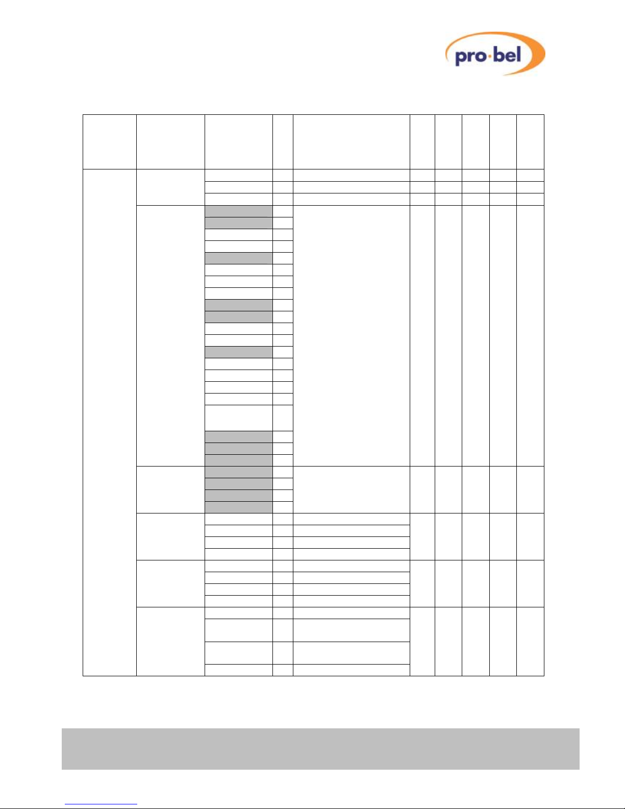
V6402, V6404, V6406, V6408
and V6418 HD converters
HU-V6402&4&6&8&18 53
5.1 Video Processing – VIDEO
Main
Menu
Sub
Menu
Value
Comment
V6402
V6404
V6406
V6408
V6418
VIDEO Source I/P 1 n
ü ü ü ü ü
I/P 2
ü ü ü ü ü
Black
ü
SY SY SY SY
O/P Std 720p59 n
ü ü
720p60
720p29
720p30
720p50
720p25
720p23
720p24
1080i59
1080i60
1080p29
1080p30
1080i50
1080p25
1080p23
1080p24
1080sf23
1080sf24
Notes:
1. Grey shaded modes
are
supported by firmware
versions
released at the time of
printing.
2. The frame-rate of the
selected O/P Std must
match
with the frame-rate of
the Video
Input.
1035i59
1035i60
576p50
O/P Std 720p59 n
ü
720p50
1080i59
1080i50
A/R 4:3 ANA n
4:3 Anamorphic
ü
16:9 LB
16:9 Letter Box
14:9 LB
14:9 Letter Box
4:3 CC
4:3 Centre Cutout
A/R 16:9 ANA n
16:9 Anamorphic
ü ü
4:3 PB
4:3 Pillar Box
14:9 PB
14:9 Pillar Box
16:9 CC
16:9 Centre Cutout
A/R Down 4:3 ANA n
4:3 Anamorphic
ü
16:9 LB
16:9 Letter Box (see
Note 1)
14:9 LB
14:9 Letter Box (see
Note 1)
4:3 CC
4:3 Centre Cutout
Page 54
V6402, V6404, V6406,V6408
and V6418 HD converters
54 Issue 6
Video Processing – VIDEO (cont.)
Main
Menu
Sub
Menu
Value
Comment
V6402
V6404
V6406
V6408
V6418
VIDEO A/R Up 16:9 ANA n
16:9 Anamorphic
ü
4:3 PB
4:3 Pillar Box
14:9 PB
14:9 Pillar Box
16:9 CC
16:9 Centre Cutout
6302Data 6302 Off n
Do not use the V6302
ü ü ü ü ü
6302 On
Use the V6302/AP
Ref Src Auto n
selects Ref I/P if present
ü
SY SY SY SY
Vid I/P
selects Video Input
Ref I/P
selects Reference Input
Anc Data Anc Blnk n
Blank Anc Data (set to
'Black')
ü
SY SY SY SY
Anc Pass
Pass Anc Data through
VFL Mode Black n
Instant Black on I/P Fail
ü
SY SY SY SY
1 sec
from Black after 1 sec…
⇓
in increments of 1 sec
13 sec
…to Black after 13 sec
To I/P 2
Switch to input 2 on I/P
Fail
Freeze
Instant Freeze on I/P
Fail
RFL Mode Min Dly n
ü
SY SY SY SY
Adj Dly
XStdMode XStd Ref n
ü
SY SY SY SY
XStd I/P
Freeze Run n
ü
SY SY SY SY
Field 1
Field 2
Frame
F Delay 0 n
FD FD FD FD FD
⇓
The maximum delay
depends on the
baseboard configuration
(24MB or 96MB) and
the detected Input
Standard.
If the Input Standard is
progressive, the number
displayed means xx‘Frames’.
If the Input Standard is
interlaced, the number
displayed means xx‘Fields’.
xx
V Delay +0 n
With Vid I/P as
reference
ü
SY SY SY SY
⇓
+749
Range dependent on
mode!
Page 55
V6402, V6404, V6406, V6408
and V6418 HD converters
HU-V6402&4&6&8&18 55
Video Processing – VIDEO (cont.)
Main
Menu
Sub
Menu
Value
Comment
V6402
V6404
V6406
V6408
V6418
Video H Delay
+0.00µs
n
With Vid I/P as
reference
ü
SY SY SY SY
⇓
+22.23µs
Range dependent on
mode!
V Timing -256
With Ext. Reference
ü
SY SY SY SY
⇓
+0 n
⇓
+255
H Timing
+0.00µs
n
With Ext. Reference
ü
SY SY SY SY
⇓
+22.23µs
Range dependent on
mode!
Norm ******
ü ü ü ü ü
Note 1: 16:9 Letter Box and 14:9 Letter Box Aspect Ratios not available in Short Delay Down
Conversion mode for V6418.
Page 56
V6402, V6404, V6406,V6408
and V6418 HD converters
56 Issue 6
5.2 Operating Conditions – STATUS
Main
Menu
Sub
Menu
Value
Comment
V6402
V6404
V6406
V6408
V6418
STATUS Variant V6402
Frame Synchroniser
ü ü ü ü
V6404
HD Down Converter
V6406
HD Up Converter
V6408
HD Cross Converter
V6418
HD Converter
Options None
No extra option
enabled
ü ü ü ü ü
F Sync
Frame Synchroniser
FD
Frame Delay
AH
Audio Handling
CP
Closed Captioning
V6302 Attached
indicates presence of
V6302 Advanced
Audio Processor
ü ü ü ü ü
None
Sub-Mod Missing
ü ü ü ü ü
Fitted
Source I/P 1
ü ü ü ü ü
I/P 2
Black
I/P Std 720p59
Auto detected Input
Standard
ü ü ü ü ü
⇓
525i59
625i50
Unknown
No Input
I/P 1 I/P 1 √
present
ü ü ü ü ü
I/P 1 x
absent
I/P 2 I/P 2 √
present
ü ü ü ü ü
I/P 2 x
absent
Ref I/P Ref √
present
ü ü ü ü ü
Ref x
absent
Ref Std 720p59
Auto detected Ref.
Standard
ü ü ü ü ü
⇓
525i59
625i50
Unknown
No Input
O/P Std 720p59
Output Standard
ü ü ü ü ü
⇓
525i59
625i50
Unknown
No Input
Page 57
V6402, V6404, V6406, V6408
and V6418 HD converters
HU-V6402&4&6&8&18 57
Operating Conditions – STATUS (cont.)
Main
Menu
Sub
Menu
Value
Comment
V6402
V6404
V6406
V6408
V6418
STATUS Aud Grps None
AH AH AH AH
1 2 3 4
Number indicates Grp
present
1 - - -
- indicates Grp
absent
Mem Size 24MBytes
Amount of SDRAM fitted
on
ü ü ü ü ü
96MBytes
Baseboard
STATUS VPModule ID 0..2
reserved
ü ü ü ü ü
GF9320
fitted on V6404/08/18 units
ID 4..6
reserved
None
IOModule ID 0
Standard I/O Daughter Board
ü ü ü ü ü
ID 1
reserved
ID 2
reserved
None
Soft Ver 05.04.05
ü ü ü ü ü
FPGA Ver 04.10
ü ü ü ü ü
CPLD Ver 00.01
ü ü ü ü ü
PCB Rev 03.02
ü ü ü ü ü
Boot Ver 01.00.01
ü ü ü ü ü
Legend:
ü Feature available on Standard version
VP VP (Video Proc Amp) option required
SY SY (Frame Synchroniser) option required
FD FD (Field/Frame Delay) option required
AH AH (Audio Handling) option required
Page 58
V6402, V6404, V6406,V6408
and V6418 HD converters
58 Issue 6
5.3 Engineering – ENG’ING
Main
Menu
Sub
Menu
Value
Comment
V6402
V6404
V6406
V6408
V6418
ENG'ING Ref Src Auto n
defaults to Ref I/P if
present
ü
SY SY SY SY
Vid I/P
selects Video Input
Ref I/P
selects Reference Input
Test Ptn TPG Off n
Test Pattern 'Off'
ü
SY SY SY SY
Bars 100
100% Colour Bars
Bars 75
75% Colour Bars
SDI Mtrx
SDI Check Field
(Pathologicals)
X-Hair
Cross Hair (Timing)
Ramp
Linear Ramp
Flat Wht
Flat White
Custom
t.b.d.
O/P EDH EDH On n
only when O/P standard is
SD
ü ü ü ü ü
EDH Off
DownConv Standard n
Standard Down
Conversion
ü
ShortDel
Short Delay Down
Conversion
Delay 0 Second n
No extra delay
FD FD FD FD FD
(see Note
1)
1 Second
Adds 1 second fixed delay
on top of arbitrary Field
Delay in 525i59 and
625i50 modes
Free-run Free Off n
ü ü ü ü ü
Free On
Sleep 0 min
LED Display never falls
asleep
ü ü ü ü ü
⇓
5 min n
Sleep after 5 minutes
(default)
⇓
30 min
Sleep after 30 minutes
LEDLevel ▓ ▓ ▓ ▓ n
LED Display Intensity
ü ü ü ü ü
Norm ******
ü ü ü ü ü
Note 1: Requires a baseboard with 96MByte Framestore
Page 59
V6402, V6404, V6406, V6408
and V6418 HD converters
HU-V6402&4&6&8&18 59
5.4 Calibration – CALIB
Main
Menu
Sub
Menu
Value
Comment
CALIB Cal Mode Cal Off n
ü ü ü ü ü
Cal On
Must be set 'On' to
enable calibration
(CntrFreq setting)
CntrFreq Frq=-128
ü ü ü ü ü
Frq= +0 n
Free-run Frequency
Frq=+127
Norm ******
ü ü ü ü ü
Legend:
ü Feature available on Standard version
VP VP (Video Proc Amp) option required
SY SY (Frame Synchroniser) option required
FD FD (Field/Frame Delay) option required
AH AH (Audio Handling) option required
Page 60

V6402, V6404, V6406,V6408
and V6418 HD converters
60 Issue 6
5.5 Configuration – CONFIG
Main
Menu
Sub
Menu
Value
Comment
CONFIG GPI GPI OFF n
GPI has no function
ü ü ü ü ü
GPI SDI1
Activate to select I/P 1
GPI SDI2
Activate to select I/P 2
GPI BARS
Activate to O/P Bars
(SY)
Banner On n
This enables the Warning
Msg.
Banner.
ü ü ü ü ü
Off
Op Mode Normal n
Manual output std
selection
ü
Up/Down
Up/Down conversion only
Def Std 720p59 n
ü
720p60
720p29
720p30
720p50
720p25
720p23
720p24
1080i59
1080i60
1080p29
1080p30
1080i50
1080p25
1080p23
1080p24
1080sf23
1080sf24
1035i59
1035i60
525i59
625i50
Default Standard
This is the default O/P
standard that will be
selected when no valid
Video Input signal is
present.
This is useful when the
unit is used as a ‘standalone’ test pattern
generator. It allows the
operator to step through
all supported modes (see
list on the left), resulting
in an instant change of
the Output standard.
DefIpStd 729p59 n
Default Standard
ü
ü ü
720p60
720p29
This is the default I/P
standard
720p30
that will be selected when
no
720p50
valid Video Input signal
is
720p25
present.
720p23
Page 61
V6402, V6404, V6406, V6408
and V6418 HD converters
HU-V6402&4&6&8&18 61
Configuration – CONFIG (cont.)
Main
Menu
Sub
Menu
Value
Comment
V6402
V6404
V6406
V6408
V6418
720p24
1080i59
1080i60
1080p29
1080p30
1080i50
1080p25
1080p23
1080p24
1080sf23
1080sf24
1035i59
1035i60
525i59
625i50
DefIpStd 525i59
ü
625i50
CONFIG
Password 0 n
ü ü ü ü ü
Variant V6402
ü ü ü ü
V6404
Factory enabled option
V6406
V6408
F Sync None
Factory enabled option
ü ü ü ü
Fitted
Vid Proc None
Factory enabled option
ü ü ü ü ü
Fitted
Fld Dely None
Factory enabled option
ü
SY SY SY SY
Fitted
Aud Hndl None
Factory enabled option
ü ü ü ü
Fitted
SD/HD Op Auto n
Auto-sensing of I/P
standard
ü ü ü ü ü
HD
I/P forced to HD operation
SD
I/P forced to SD operation
PCB Rev 0
ü ü ü ü ü
⇓
Password protected
15
H/W Rev 0
ü ü ü ü ü
⇓
Password protected
15
TestMode Off n
ü ü ü ü ü
On
Mem Test On n
Execute SDRAM Test
@Pwr-On
ü ü ü ü ü
Off
Norm ******
ü ü ü ü ü
Page 62

V6402, V6404, V6406,V6408
and V6418 HD converters
62 Issue 6
Legend:
ü Feature available on Standard version
VP VP (Video Proc Amp) option required
SY SY (Frame Synchroniser) option required
FD FD (Field/Frame Delay) option required
AH AH (Audio Handling) option required
Page 63
V6402, V6404, V6406, V6408
and V6418 HD converters
HU-V6402&4&6&8&18 63
5.6 Video Proc Amp – PROC AMP
Note: This menu is only available on modules with the VP (Video Proc Amp) option enabled.
Main
Menu
Sub
Menu
Value
Comment
PROC AMP V Gain -6.02dB
VP VP VP VP VP
⇓
-0.00dB n
Video Gain Control
⇓
+6.01dB
C Gain -6.02dB
VP VP VP VP VP
⇓
-0.00dB n
Chroma Gain Control
⇓
+6.01dB
Blk Lvl -128
VP VP VP VP VP
⇓
+0 n
Black Level Control
⇓
+127
Hue -45.00°
VP VP VP VP VP
⇓
+0.00° n
Hue Control
⇓
+44.65°
Bypass Byp Off n
Proc Amp Bypass Off
VP VP VP VP VP
Byp On
Proc Amp Bypass On
Dyn Rdn DR On n
Dynamic Rounding On
VP VP VP VP VP
DR Off
Dynamic Rounding Off
Hrd Clip HClp Off n
Hard Clipping Off
VP VP VP VP VP
HClp On
Hard Clipping On
Fade>Blk F>B Off n
Fade to Black Off
VP VP VP VP VP
F>B On
Fade to Black On
Norm ******
VP VP VP VP VP
Legend:
ü Feature available on Standard version
VP VP (Video Proc Amp) option required
SY SY (Frame Synchroniser) option required
FD FD (Field/Frame Delay) option required
AH AH (Audio Handling) option required
Page 64
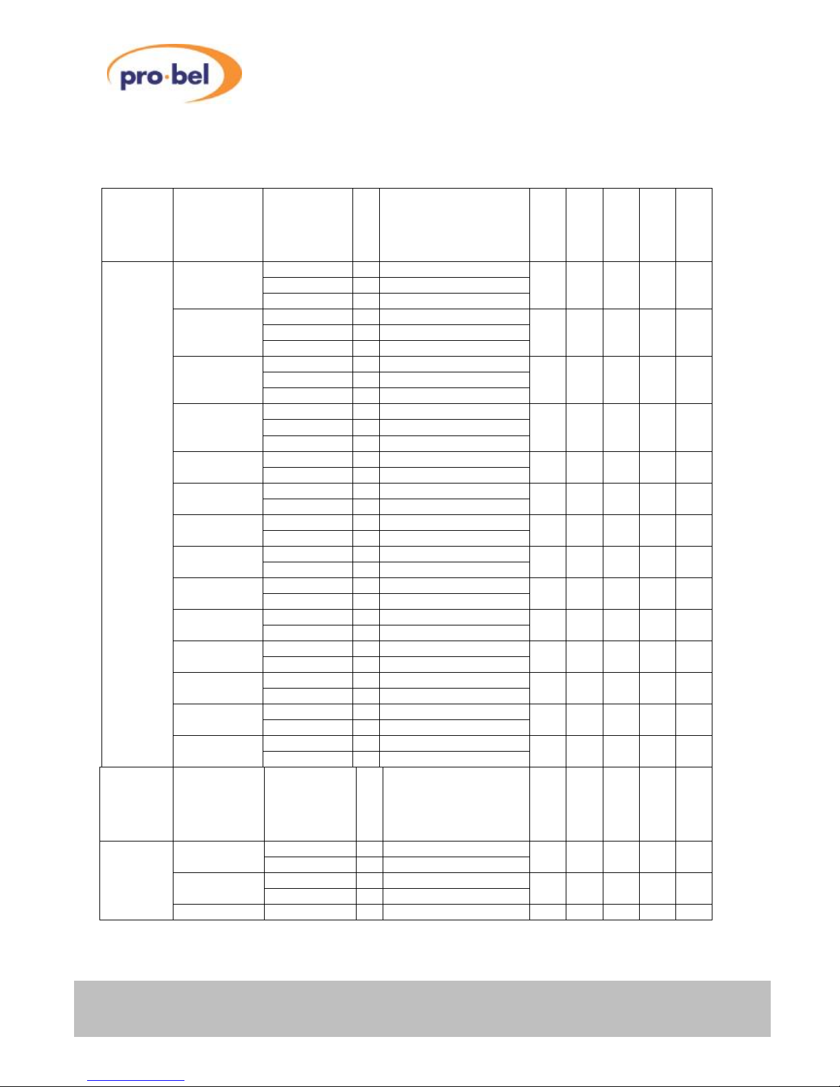
V6402, V6404, V6406,V6408
and V6418 HD converters
64 Issue 6
5.7 Audio Handling – AUDIO
Note: This menu is only available on modules with the AH (Audio Handling) option enabled.
Main
Menu
Sub
Menu
Value
Comment
V6402
V6404
V6406
V6408
V6418
AUDIO Aud Grp1 Grp1 20b n AH
Grp1 24b
Grp1 Off
Aud Grp2 Grp2 20b n AH
Grp2 24b
Grp2 Off
Aud Grp3 Grp3 20b n AH
Grp3 24b
Grp3 Off
Aud Grp4 Grp4 20b n AH
Grp4 24b
Grp4 Off
Aud Grp1 Grp1 On n AH AH
Grp1 Off
Aud Grp2 Grp2 On n AH AH
Grp2 Off
Aud Grp3 Grp3 On n AH AH
Grp3 Off
Aud Grp4 Grp4 On n AH AH
Grp4 Off
En Grp1 Grp1 On n AH
Grp1 Off
En Grp2 Grp2 On n AH
Grp2 Off
En Grp3 Grp3 On n AH
Grp3 Off
En Grp4 Grp4 On n AH
Grp4 Off
Grp1 Res Grp1 20b n AH
Grp1 24b
Grp2 Res Grp2 20b n AH
Grp2 24b
Main
Menu
Sub
Menu
Value
Comment
V6402
V6404
V6406
V6408
V6418
Grp3 Res Grp3 20b n AH
Grp3 24b
Grp4 Res Grp4 20b n AH
Grp4 24b
Norm ****** AH AH AH AH
Page 65
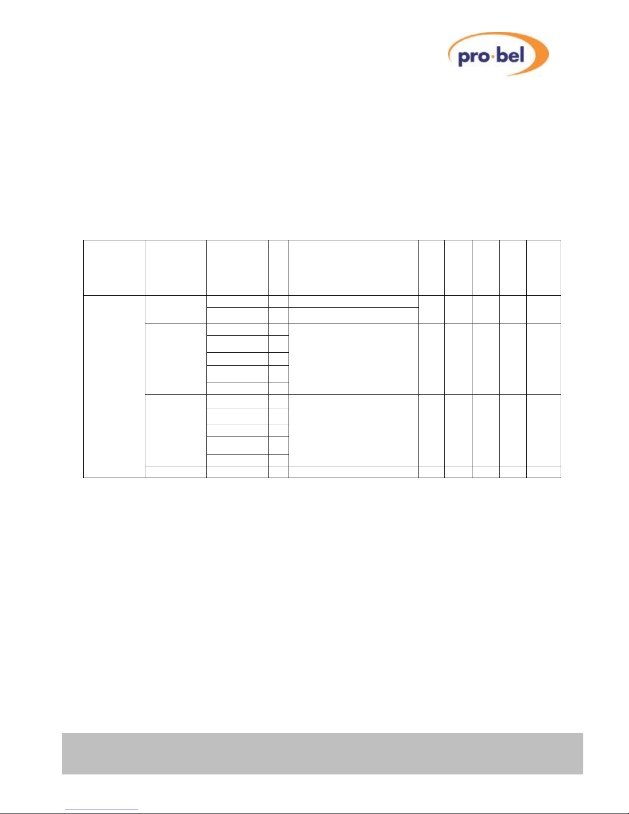
V6402, V6404, V6406, V6408
and V6418 HD converters
HU-V6402&4&6&8&18 65
Legend:
ü Feature available on Standard version
VP VP (Video Proc Amp) option required
SY SY (Frame Synchroniser) option required
FD FD (Field/Frame Delay) option required
AH AH (Audio Handling) option required
5.8 Closed Captioning – CCAPTION
Note: This menu is only available on modules with the CP (CLOSED CAPTIONING) option enabled.
Main
Menu
Sub
Menu
Value
Comment
V6402
V6404
V6406
V6408
V6418
CCAPTION O/P CC CC On n
Output captions if present
CP CP CP CP
CC Off
Disable caption output
1 CP CP CP
⇓
9 n
⇓
ANC1080i
20
Set the output VANC line
that the SMPTE 334M
Packets will be embedded
on when the output is
1080i.
1
⇓
9 n
⇓
ANC 720P
25
Set the output VANC line
that the SMPTE 334M
packets will be embedded
on when the output is 720p
CP CP CP*
******
CP CP CP CP
* Local only control on the V6418
Legend:
ü Feature available on Standard version
VP VP (Video Proc Amp) option required
SY SY (Frame Synchroniser) option required
FD FD (Field/Frame Delay) option required
AH AH (Audio Handling) option required
CP CP (Closed Caption) option required
Page 66

V6402, V6404, V6406,V6408
and V6418 HD converters
66 Issue 6
6 APPENDIX A
6.1 Trouble Shooting Guide (Frequently Asked Questions)
This section is to be a help in solving some common difficulties. If there is no control from the front panel
first check that the Rem/Local switch is set to Local.
Q: My V64xx powers-up with a static test pattern or black output, although a valid SDI video signal
is connected to one of its inputs.
A: 1. Check whether the Front Panel HD/SD LED is lit. This indicates that a signal is being received.
2. Check whether the Input selection is set correctly. VIDEO : Source : I/P 1 (or I/P 2)
3. Check that the Test Pattern Generator is turned off. ENG'ING : Test Ptn : TPG Off
4. Make sure that the mode of operation (SD/HD) matches with your Input Standard.
Set to 'Auto' sensing if in doubt. CONFIG : SD/HD Op : Auto
Q: My V64xx does not synchronise to the external reference.
A:
1. Check whether the Front Panel Ref. LED is lit. This indicates the presence of an ext. reference.
2. Check whether the ext. reference input is selected. VIDEO : Ref Src : Auto (or Ref IP)
Q: It seems that embedded Audio data does not get passed through the Frame Synchroniser (in
fact, no Ancillary data whatsoever).
A: Check whether the Anc Data enable control is set properly. VIDEO : Anc Data : Anc Pass
Q: I want to add a number of frames extra delay to the output, but I cannot find the associated menu item.
A:
You need a V6402 (or a V6404/06/08/18SY) with the Field/Frame-Delay (FD) option enabled. This is a
factory installed option and requires a password in order to enable it. If the option is enabled, you will
find the corresponding control menu under VIDEO : F Delay.
Q: The output generated by my V6406/08/18 looks corrupt.
A: Make sure that the selected Output Standard has the same frame-rate as the Input signal.
Q: I want to use my V6402 as a stand-alone Test Pattern Generator, but I cannot see anything on
the Monitor.
A: 1. Make sure that the selected 'Default Standard' is compatible with your Monitor specification
(CONFIG : Def Std). Note that some Broadcast Monitors cannot cope with progressively
scanned modes with frame-rates less than 50Hz.
2. Check whether the TPG is turned on an that you have not deliberately selected a 'Black' test
pattern (ENG'ING : TestPtn : Bars 100, Bars 75, etc.)
Page 67

V6402, V6404, V6406, V6408
and V6418 HD converters
HU-V6402&4&6&8&18 67
Q: The Proc Amp does not work.
A: Check whether it is set to Bypass. PROC AMP : Bypass : Byp Off
Q: The display never goes to sleep.
A: Check whether the Sleep delay has been set to 0 Mins, which means stay awake.
Page 68
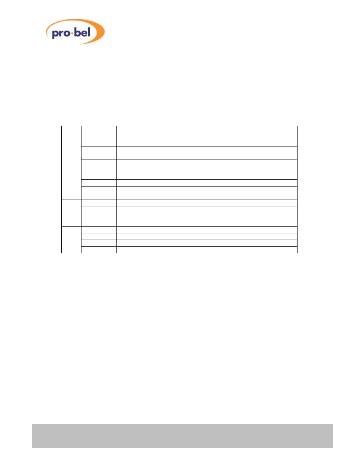
V6402, V6404, V6406,V6408
and V6418 HD converters
68 Issue 6
6.2 Initialization, Power On-Selftest & Error Messages
6.2.1 Board Initialization Sequence
Every time a board goes through a power-on cycle, either by re-seating the board in the rack or by
triggering the manual reset, a sequence of initialisation and self-test events is being carried out by the onboard microcontroller.
If anything goes wrong, an error message is shown on the front panel display and program execution halts.
The following table shows the error messages and their meaning:
ERROR 01 Flash erasing failed
ERROR 02 Flash programming failed
ERROR 03 Main program checksum error after programming
ERROR 04 Bootloader checksum error after programming
ERROR 05 No program loaded and no valid upgrade in Flash Stick
Flash
upgrading
ERROR 06 Bootloader upgrade required but no valid bootloader upgrade in Flash
Stick
ERROR 07 STATUS stayed low after CONFIG pulsed low
ERROR 08 DONE stayed high after CONFIG pulsed low
ERROR 09 STATUS went low during configuration
FPGA
Load
ERROR 10 DONE stayed low after configuration
ERROR 11 Error writing to local EEPROM
ERROR 12 Error reading from EEPROM
ERROR 13 Initialising EEPROM to default data
Local
EEPROM
ERROR 14 Initialising parameters to default data
ERROR 15 Receive buffer overflow
ERROR 16 Receive overrun
ERROR 17 Receive framing error
Debug
Port
ERROR 18 Receive parity error
Page 69
V6402, V6404, V6406, V6408
and V6418 HD converters
HU-V6402&4&6&8&18 69
6.2.2 SDRAM Test
An automatic SDRAM test is being carried out on the V64xx baseboard with firmware V02.00 (or higher)
as part of the power-on self-test sequence. This is subject to the corresponding setting in the CONFIG
Menu (Mem Test ON/OFF) - Mem Test is set to 'ON' by default.
In case of an error, the front panel display will show one of the following SDRAM test exit codes:
MEM ERR0 SDRAM Databus Bit(s) stuck @ 0
MEM ERR1 SDRAM Databus Bit(s) stuck @ 1
MEM ERR2 Neighbouring SDRAM Databus Bit(s) are shorted
MEM ERR3 Neighbouring SDRAM Databus Bit(s) are shorted
MEM ERR4 SDRAM Address lines (A10-A0) are shorted or open
MEM ERR5 SDRAM Bank Select lines (BA0, BA1) are shorted or open
MEM ERR6 Error whilst filling the SDRAM with 'black' pattern
SDRAM
Test
MEM ERR7 Timeout error (internal FPGA problem)
6.3 Menu Structures
The following pages summarize the menu structures on all the modules.
Please note that the presence of some sub-menus depend on the factory configuration of your
module. In other words, if an option is not fitted, the entire sub-menu belonging to it will not appear in
the menu structure.
Page 70
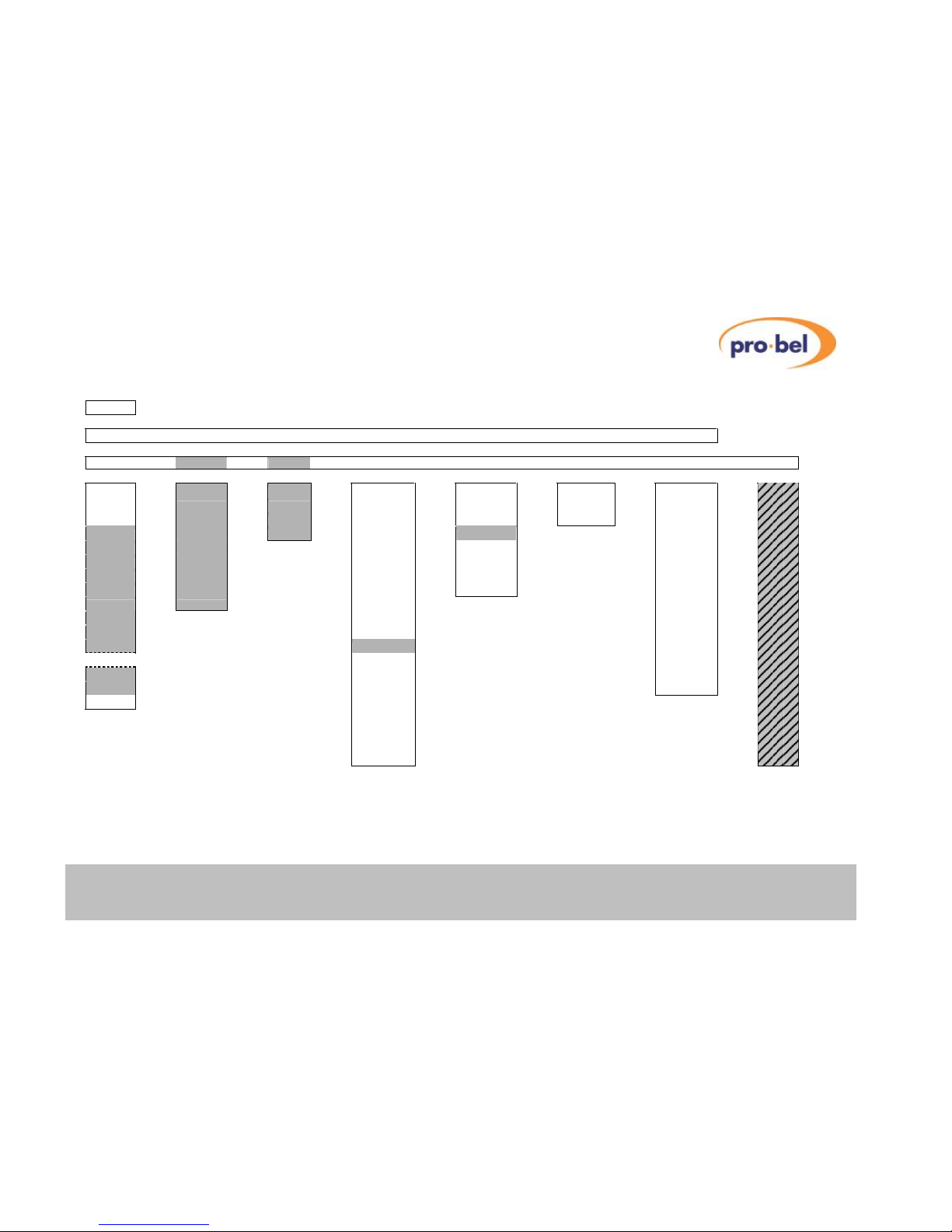
VISTEK V6402, V6404, V6406, V6408 and V6418
HU-V6402&4&6&8&18 70
6.3.1 V6402 HD Frame Synchroniser Menu Structure
SLEEP
▼
V6402 ◄► I/P 1 ◄► I/P 2 ◄► REF ◄► I/P Std ◄► O/P Std ◄► Ref Std
▼
VIDEO ◄► PROC AMP ◄► AUDIO ◄► STATUS ◄► ENG’ING ◄► CALIB ◄► CONFIG ◄► TEST
▼
▼
▼
▼
▼
▼
▼
▼
Source
V Gain
Aud Grp1
Variant
Ref Src
Cal Mode
Banner
A/R
C Gain
Aud Grp2
Option
Test Ptn
CntrFreq
DeflpStd
6302Data
Blk Lvl
Aud Grp3
V6302
O/P EDH
Norm
Password
Ref Src
Hue
Aud Grp4
Sub-Mod
Delay³
Variant
Anc Data
Bypass
Source
Free-run
F Sync
VFL Mode
Dyn Rnd
I/P Std
Sleep
Vid Proc
RFL Mode
Hrd Clip
I/P 1
LEDLevel
C1 Captn
XStdMode
Fade>Blk
I/P 2
Norm
Frme Dly
Freeze
Norm
Ref I/P
Aud Hndl
F Delay
Ref Std
SD/HD Op
V Delay¹
O/P Std
PCB Rev
H Delay¹
Aud Grps
H/W Rev
Or
Mem Size
TestMode
V Timing²
VPModule
Mem Test
H Timing²
IO Module
Norm
Norm
Soft Ver
FPGA Ver
CPLD Ver
PCB Ver
Boot Ver
For test and debug only!
Legend: n Password enabled Option(s)
Notes: 1. Reference is Vid I/P
2. Reference is Ref I/P
3. Requires ‘FD’ option, only available with 525i59 and 625i50 Input Std.
Page 71
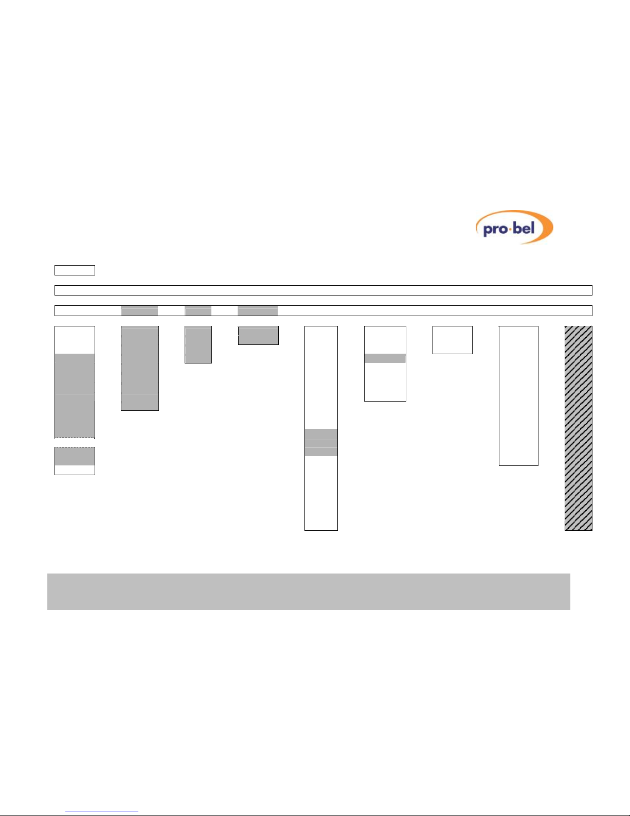
VISTEK V6402, V6404, V6406, V6408 and V6418
HU-V6402&4&6&8&18 71
6.3.2 V6404 HD Down Converter Menu Structure
SLEEP
▼
V6404 ◄► I/P 1 ◄► I/P 2 ◄► REF ◄► I/P Std ◄► O/P Std ◄► CEA608 ◄► CEA708 ◄► Ref Std
▼
VIDEO ◄► PROC AMP ◄► AUDIO ◄► CCAPTION ◄► STATUS ◄► ENG’ING ◄► CALIB ◄► CONFIG ◄► TEST
▼
▼
▼
▼
▼
▼
▼
▼
▼
Source
V Gain
Aud Grp1
O/P CC
Variant
Ref Src
Cal Mode
Banner
A/R
C Gain
Aud Grp2
Norm
Option
Test Ptn
CntrFreq
DeflpStd
6302Data
Blk Lvl
Aud Grp3
V6302
O/P EDH
Norm
Password
Ref Src
Hue
Aud Grp4
Sub-Mod
Delay³
Variant
Anc Data
Bypass
Source
Free-run
F Sync
VFL Mode
Dyn Rnd
I/P Std
Sleep
Vid Proc
RFL Mode
Hrd Clip
I/P 1
LEDLevel
Cl Captn
XStdMode
Fade>Blk
I/P 2
Norm
Frme Dly
Freeze
Norm
Ref I/P
Aud Hndl
F Delay
Ref Std
SD/HD Op
V Delay¹
O/P Std
PCB Rev
H Delay¹
CEA608
H/W Rev
Or
CEA708
TestMode
V Timing²
Aud Grps
Mem Test
H Timing²
Mem Size
Norm
Norm
VPModule
IO Module
Soft Ver
FPGA Ver
CPLD Ver
PCB Ver
Boot Ver
For test and debug only!
Legend: n Password enabled Option(s)
Notes: 1. Reference is Vid I/P 2. Reference is Ref I/P
3. Requires ‘FD’ option, only available with 525i59 and 625i50 Input Std.
Page 72
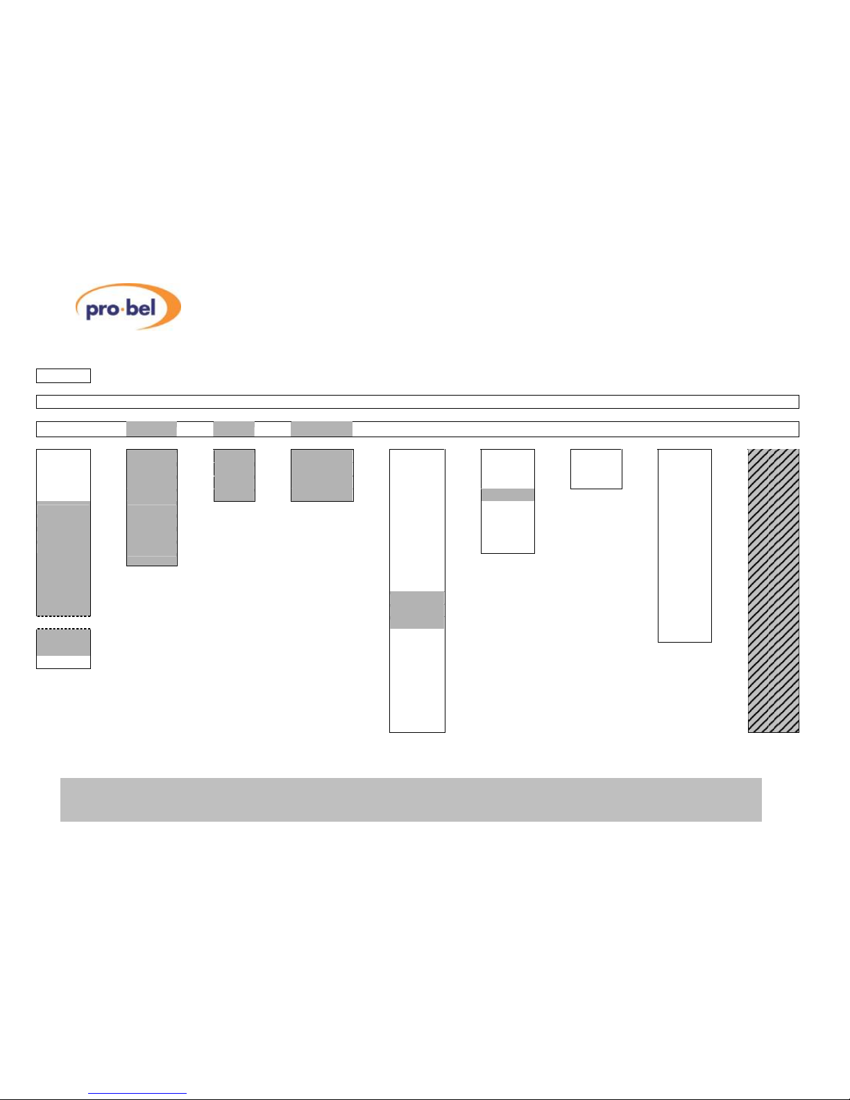
VISTEK V6402, V6404, V6406, V6408 and V6418
72 Issue 6
6.3.3 V6406 HD Up Converter Menu Structure
SLEEP
▼
V6406 ◄► I/P 1 ◄► I/P 2 ◄► REF ◄► I/P Std ◄► O/P Std ◄► CEA608 ◄► CEA708 ◄► Ref Std
▼
VIDEO ◄► PROC AMP ◄► AUDIO ◄► CCAPTION ◄► STATUS ◄► ENG’ING ◄► CALIB ◄► CONFIG ◄► TEST
▼
▼
▼
▼
▼
▼
▼
▼
▼
Source
V Gain
Aud Grp1
O/P CC
Variant
Ref Src
Cal Mode
Banner
O/P Std
C Gain
Aud Grp2
ANC1080i
Option
Test Ptn
CntrFreq
DeflpStd
A/R
Blk Lvl
Aud Grp3
ANC 720p
V6302
O/P EDH
Norm
Password
6302Data
Hue
Aud Grp4
Norm
Sub-Mod
Delay³
Variant
Ref Src
Bypass
Source
Free-run
F Sync
Anc Data
Dyn Rnd
I/P Std
Sleep
Vid Proc
VFL Mode
Hrd Clip
I/P 1
LEDLevel
Cl Captn
RFL Mode
Fade>Blk
I/P 2
Norm
Frme Dly
XStdMode
Norm
Ref I/P
Aud Hndl
Freeze
Ref Std
SD/HD Op
F Delay
O/P Std
PCB Rev
V Delay¹
CEA608
H/W Rev
H Delay¹
CEA708
TestMode
Or
Aud Grps
Mem Test
V Timing²
Mem Size
Norm
H Timing²
VPModule
Norm
IO Module
Soft Ver
FPGA Ver
CPLD Ver
PCB Ver
Boot Ver
For test and debug only!
Legend: n Password enabled Option(s)
Notes: 1. Reference is Vid I/P 2. Reference is Ref I/P
3. Requires ‘FD’ option, only available with 525i59 and 625i50 Input Std
Page 73
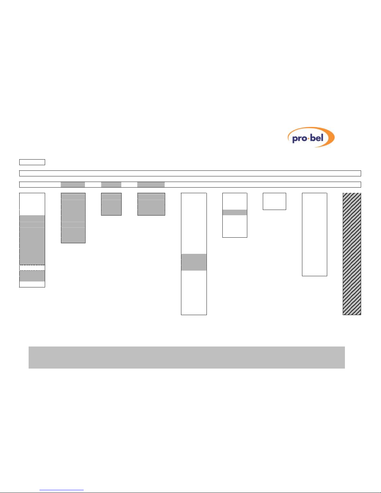
VISTEK V6402, V6404, V6406, V6408 and V6418
HU-V6402&4&6&8&18 73
6.3.4 V6408 HD Cross Converter Menu Structure
Legend: n Password enabled Option(s)
Notes: 1. Reference is Vid I/P 2. Reference is Ref I/P
3. Requires ‘FD’ option, only available with 525i59 and 625i50 Input Std
SLEEP
▼
V6408 ◄► I/P 1 ◄► I/P 2 ◄► REF ◄► I/P Std ◄► O/P Std ◄► CEA608 ◄► CEA708 ◄► Ref Std
▼
VIDEO ◄► PROC AMP ◄► AUDIO ◄► CCAPTION ◄► STATUS ◄► ENG’ING ◄► CALIB ◄► CONFIG ◄► TEST
▼
▼
▼
▼
▼
▼
▼
▼
▼
Source
V Gain
Aud Grp1
O/P CC
Variant
Ref Src
Cal Mode
Banner
O/P Std
C Gain
Aud Grp2
ANC1080i
Option
Test Ptn
CntrFreq
DeflpStd
A/R
Blk Lvl
Aud Grp3
ANC 720p
V6302
O/P EDH
Norm
Password
6302Data
Hue
Aud Grp4
Norm
Sub-Mod
Delay³
Variant
Ref Src
Bypass
Source
Free-run
F Sync
Anc Data
Dyn Rnd
I/P Std
Sleep
Vid Proc
VFL Mode
Hrd Clip
I/P 1
LEDLevel
Cl Captn
RFL Mode
Fade>Blk
I/P 2
Norm
Frme Dly
XStdMode
Norm
Ref I/P
Aud Hndl
Freeze
Ref Std
SD/HD Op
F Delay
O/P Std
PCB Rev
V Delay¹
CEA608
H/W Rev
H Delay¹
CEA708
TestMode
Or
Aud Grps
Mem Test
V Timing²
Mem Size
Norm
H Timing²
VPModule
Norm
IO Module
Soft Ver
FPGA Ver
CPLD Ver
PCB Ver
Boot Ver
For test and debug only!
Page 74
VISTEK V6402, V6404, V6406, V6408 and V6418
74 Issue 6
6.3.5 V6418 HD Converter Menu Structure
SLEEP
▼
V6418 ◄► I/P 1 ◄► I/P 2 ◄► REF ◄► I/P Std ◄► O/P Std ◄► CEA608 ◄► CEA708 ◄► Ref Std
▼
VIDEO ◄► PROC AMP ◄► AUDIO ◄► CCAPTION ◄► STATUS ◄► ENG’ING ◄► CALIB ◄► CONFIG ◄► TEST
▼
▼
▼
▼
▼
▼
▼
▼
▼
Source
V Gain
En Grp1
O/P CC
Variant
Ref Src
Cal Mode
Banner
O/P Std
C Gain
En Grp2
ANC1080i
Option
Test Ptn
CntrFreq
Op Mode
A/R Down
Blk Lvl
En Grp3
ANC 720p
V6302
O/P EDH
Norm
DeflpStd
A/R Up
Hue
En Grp4
Norm
Sub-Mod
Delay³
Password
6302Data
Bypass
Grp1 Res
Source
DownConv
Variant
Ref Src
Dyn Rnd
Grp2 Res
I/P Std
Free-run
F Sync
Anc Data
Hrd Clip
Grp3 Res
I/P 1
Sleep
Vid Proc
VFL Mode
Fade>Blk
Grp4 Res
I/P 2
LEDLevel
C1 Captn
RFL Mode
Norm
Ref I/P
Norm
Frme Dly
XStdMode
Ref Std
Aud Hndl
Freeze
O/P Std
SD/HD Op
F Delay
CEA608
PCB Rev
V Delay¹
CEA708
H/W Rev
H Delay¹
Aud Grps
TestMode
Or
Mem Size
Mem Test
V Timing²
VPModule
Norm
H Timing²
IO Module
Norm
Soft Ver
FPGA Ver
CPLD Ver
PCB Ver
Boot Ver
For test and debug only!
Legend: n Password enabled Option(s)
Notes: 1. Reference is Vid I/P 2. Reference is Ref I/P
3. Requires ‘FD’ option, only available with 525i59 and 625i50 Input St
 Loading...