

pro bel SIRIUS GOLD Getting Started Manual
This leaflet is designed for quick reference only, and the
user will have to refer to the User Guides for both Sirius
and Nebula for detailed information. Nebula is th e Pro-Bel
router control system included with a Sirius Master router.
Connecting Your Router
See the rear view diagram included in this leaflet.
If ‘clean’ switching is required, an appropriate reference
must be connected such as an analogue video ‘black and
burst’ feed of either 625 line PAL, 525 line NTSC standard,
HDTV; or all three for a mixed standard system. A digital
audio router may require a balanced or unbalanced AES
reference if it is not being run synchronously with video.
To connect a Nebula database editor, use the ‘RS232 configuration port’ for ‘CTRL A’, this will work unless a
controller changeover has occurred, in which case the ‘CTRL B’ port must be used.
An external control system may be connected using an Ethernet or RS485 serial port. Ensure that the jumpers
on the 2434 control card are configured appropriately by referring to the ‘Configuring the control module’
section of the Sirius user guide.
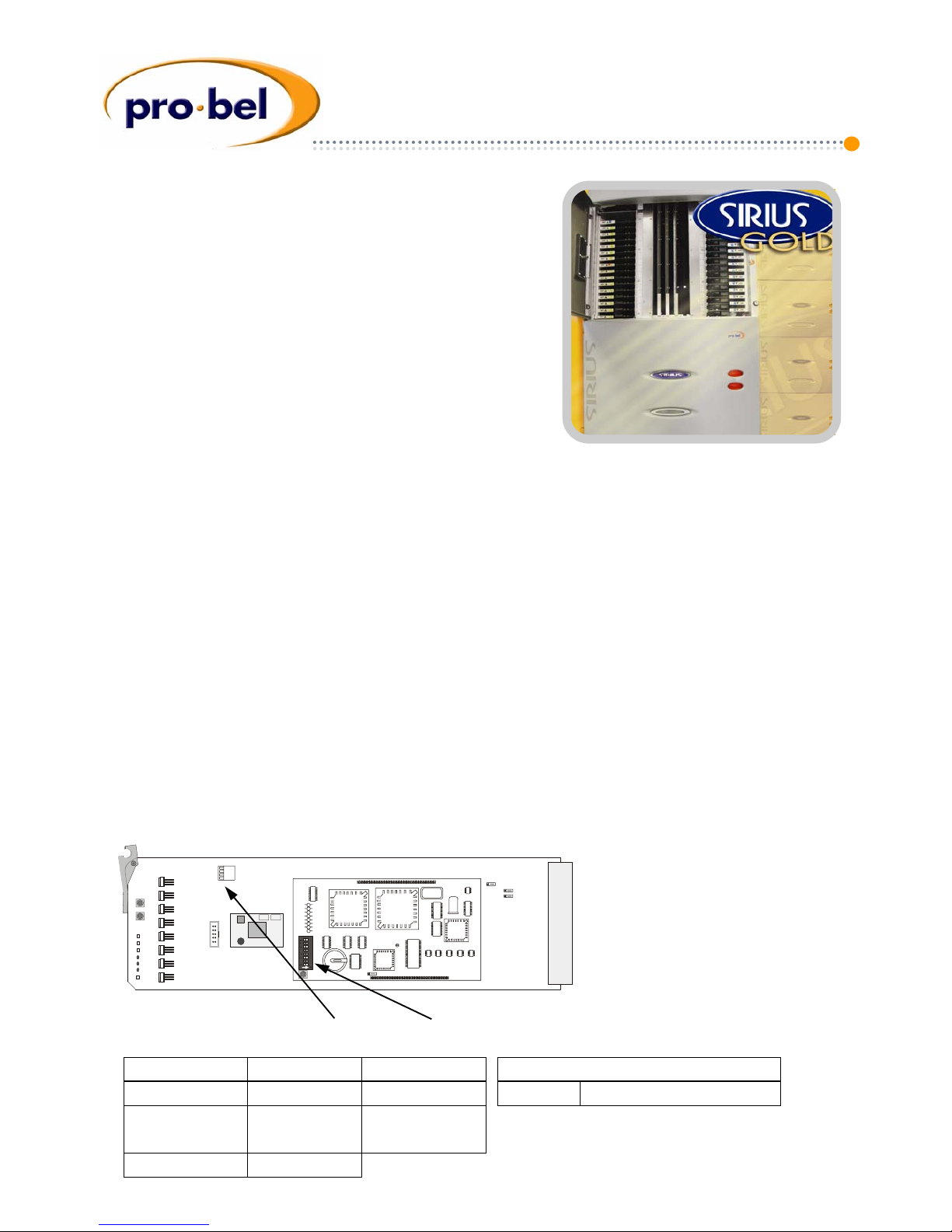
Controlling Your Router
Every Sirius router must have at least one control card, this may be a 2434 or 2435. Two of the same type may
be fitted for redundancy. The 2434 card is the Nebula controller, which holds the system database. The 2435 is
an ‘interface’ card and is only fitted in frames that are ‘slaved’ to frames with a 2434 Nebula controller. The
only difference between the two card types is that the 2434 is fitted with a 2445 sub-board, and the 2435 is
not.
There are two sets of switches on the router control card which determine the router operation, and these are
described in this leaflet. There is also a set of 8 HE X switches for ‘partitioning’ the router beyond a single level,
the user must refer to the Sirius user guide for such a configuration, however, if only one level is required th ese
switches are set to zero.
Control Card Switch Settings
Configuration switches on the 2434 card and the 2445 sub-board
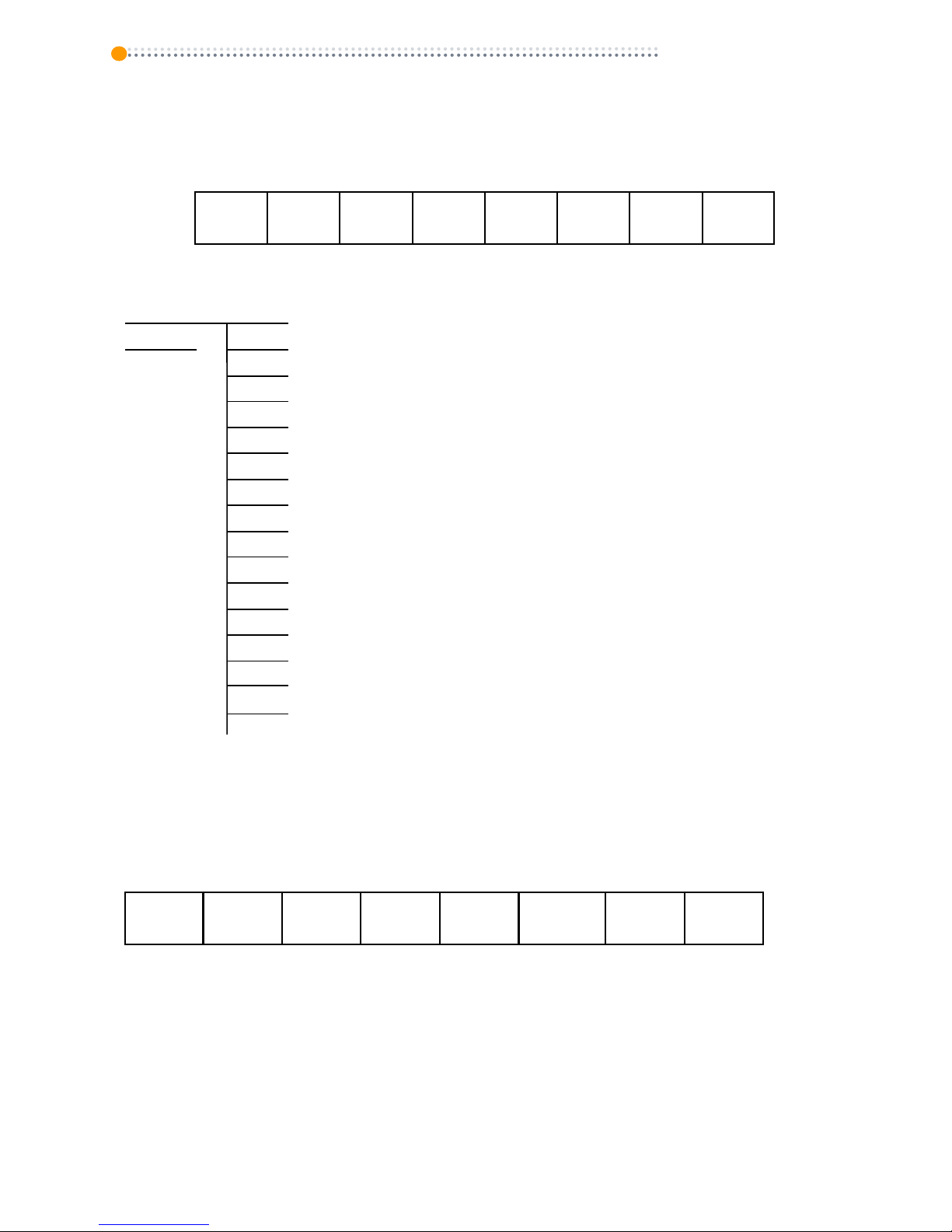
Switches ON OFF
1 Master Slave
2
Defines 2434
(with 2445)
Defines 2435
(without 2445)
3 & 4
ON
1
ON: Master, OFF: Slave
2445 sub-board configuration switch
It is important that when configuring a control
module, the 2434 configuration switch 1 setting
matches the 2445 sub-board.
Getting Started Guide
SIRIUS GOLD
6276XY (addr 1, see documentation for key layout)
6276XY (addr 2, see documentation for key layout)
6276XY-MON (addr 3, 6276XY—Mon (Sirius)
6277-8 (addr 4, all sources, dest 1-8, 65-72)
6277-8 (addr 5, all sources, dest 9-16, 73-80)
6277-8 (addr 6, all sources, dest 17-24, 81-88)
6277-8 (addr 7, all sources, dest 25-32, 89-96)
6277-8 (addr 8, all sources, dest 33-40, 97-104)
6277-8 (addr 9, all sources, dest 41-48, 105-112)
6277-8 (addr 10, all sources, dest 49-56, 113-120)
6277-8 (addr 11, all sources, dest 57-64, 121-128)
6705 BPX (addr 12, sources 1-32, dest 1)
6705 BPX (addr 13, sources 33-64, dest 1)
6705 BPX (addr 14, sources 65-96, dest 1)
6705 BPX (addr 15, 6706, sources 97-128, dest 1)
6705 SplitXY (addr 16, 6706, sources 1-16, dest 1-16)
RS485-2
Panel Settings
6276XY and 6277-8 Panel Switch settings at rear
UP
1
UP
2
UP
3
DWN
4
DWN
5
UP = 6277
DWN = 6276
6
DWN
7
UP
8
6705 BPX - sw 7 ON, all others OFF
6705 SplitXY - sw 6 & sw 7 ON, all others OFF
Note: The RS485 cable is wired pin to pin. Ensure the multi-drop address is set correctly for each panel.
If using a configured database the Nebu la Editor will show this as CURR_SYS, and the panels may be
configured as required. SW7 = ON. Refer to the handbook for editing details.
RS485-1
Sirius Router Fixed Database Panel Configuration. For RS485-2 panel details, see documentation.
Fixed Database Control Sub-Board Switch Settings
Use the following settings when connecting control panels directly to ports RS485-1 and 2.
Master 2434 switch settings shown in bold. For slave control card, SW1 is OFF.
ON
sw
OFF
Mstr
1
Slve
20MHz
2
10MHz
3
OFF
38400
4
9600
525
5
625
Auto
6
manual
Config
7
fxd
Panels
8
genrl
 Loading...