


1
AXIS USER GUIDE
Contents
1 Introduction 4
2 Installation 5
2.1 Rear panel layouts 5
2.1.1 Digital/ Analogue Video and Unbalanced Digital Audio 5
2.1.2 Balanced Digital Audio 5
2.1.3 Analogue Audio 5
2.1.4 HD Digital Video 5
2.2 Ventilation 6
2.3 Power supplies 6
2.4 Signal connections 7
2.4.1 Analogue/ digital video, unbalanced digital audio and HD
digital video 7
2.4.2 Digital audio (balanced) connector pinout 8
2.4.3 Analogue audio connector pinout 9
2.5 Control connections 10
2.5.1 Serial control connector 10
2.5.2 Parallel control connector 12
2.6 LED indicators 13
2.7 Video reference 13
2.8 AES reference 14
2.9 Setting the level switches 14
3 Hardware configuration 15
3.1 Router details 15
3.1.1 Master frames 15
3.1.2 Slave frames 16

2 Issue 6
AXIS user guide
3.2 System interconnections 17
3.2.1 Multilevel systems 17
3.2.2 Control panel interconnection 17
3.2.3 Other control options 18
4 Fixed database systems 19
4.1 Database settings 19
4.2 Panel details 20
4.3 Remote control options 21
4.4 Port definitions 21
4.4.1 Port characteristics 21
4.4.2 Pro-Bel General Switcher Protocol (SW-P-02) 22
5 Editable database systems 23
5.1 Level types 23
5.2 Panel details 24
5.2.1 Supported Devices 24
5.2.2 General panel details 25
5.2.3 Panel features 25
5.2.4 Assigning Audio parameters from panels 35
5.3 Remote control options 39
5.4 Port definitions 40
5.4.1 Port characteristics 40
5.4.2 Pro-Bel General Switcher Protocol (SW-P-02) 40
5.4.3 Pro-Bel General Remote Control Protocol (SW-P-08) 41
6 Configuring the database 42
6.1 The Axis database editor 42
6.1.1 Hardware requirements 42
6.1.2 Installing the Editors 42
6.2 Understanding the database 43
6.2.1 Level types 43
6.2.2 Source and destination associations 43
6.2.3 Source names 45

HU-AXIS
3
AXIS user guide
6.2.4 Destination association names 45
6.2.5 Route inhibits 45
6.2.6 Salvos 45
6.2.7 Configuring source keypads 45
6.2.8 Configuring destination keypad 46
6.2.9 Assigning panel types and keypads 46
6.2.10 Assigning source overrides 46
6.2.11 Assigning controllable destination association indices 46
6.2.12 Assigning controllable levels/brightness 46
6.2.13 Configuring port characteristics 46
6.2.14 Audio features 46
7 Trouble shooting 48
8 Specification 50
8.1 General 50
8.1.1 Control 50
8.1.2 Power supplies 50
8.1.3 General 50
8.1.4 Temperature range 50
8.2 Performance 51
8.2.1 Digital Video 51
8.2.2 HD/SD Digital Video 51
8.2.3 Analogue video 52
8.2.4 Digital audio (Balanced and Unbalanced) 53
8.2.5 Analogue audio 53

4 Issue 6
AXIS user guide
1 Introduction
The Axis router family addresses the need for smaller utility routers, by providing a range of
compact, 1U, 16x16 self contained routing switchers for SDI and HD video, analogue video,
balanced or unbalanced AES digital audio and stereo analogue audio signal formats.
Axis routers can be supplied in either Master or Slave frame configurations permitting
multilevel routing systems with up to eight levels to be constructed. Increasing the flexibility
of the system further, Master frames are supplied with an internal control module and
contain an editable database.
The system supports a wide range of standard Pro-Bel control panels, however Master
frames can also be supplied with an integral 16x16 X-Y control panel, permitting ‘plug and
play’ operation straight from the box.
It should be noted that Axis frames contain no user serviceable parts, therefore should this
product require servicing, you should refer to Pro-Bel or your local distributor.
HU-AXIS
5
AXIS user guide
2 Installation
The Axis range of self-contained routing switchers are supplied as fixed frame units and
therefore do not contain any user serviceable parts.
Should you experience any difficulties with any Axis frame, please refer first to Chapter 7 –
Trouble Shooting, and then if you are still having difficulties contact customer support as
detailed in Chapter 9 of this handbook.
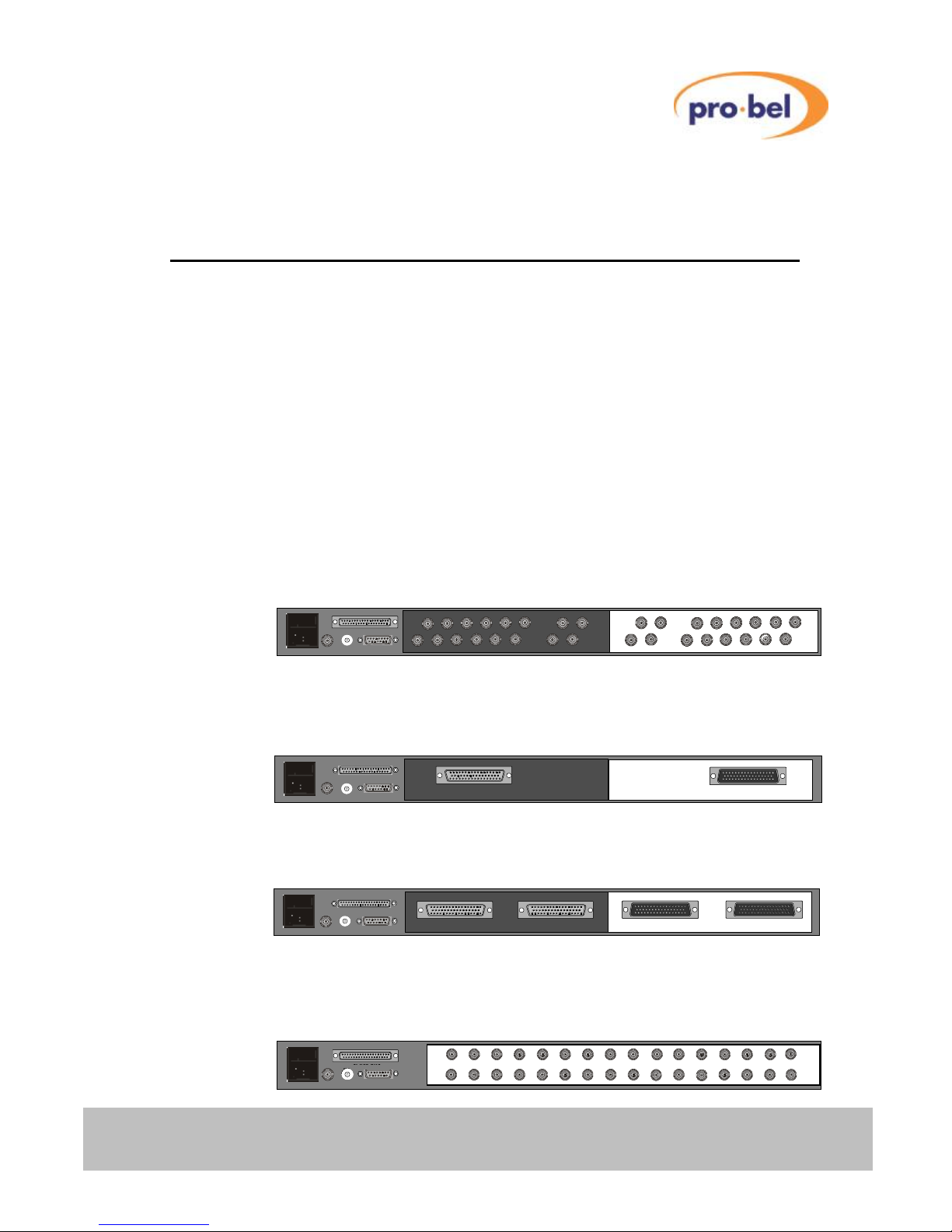
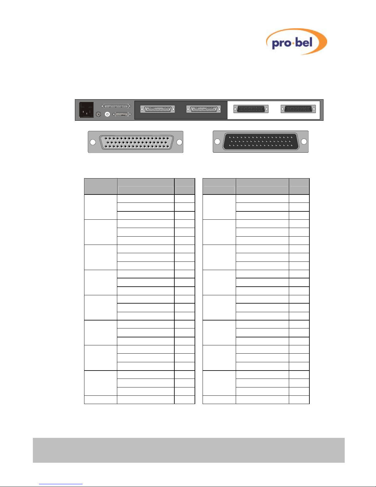
2.1 Rear panel layouts
The layout for the rear of each Axis frame variant is shown below.
2.1.1 Digital/ Analogue Video and Unbalanced Digital Audio
2.1.2 Balanced Digital Audio
2.1.3 Analogue Audio
2.1.4 HD Digital Video
SLAVE BUS
VID REF LEVEL CONTROL
1
2
0
8
3
4
5
6
7
9
A
B
C
D
E
F
1
2
0
8
3
4
5
6
7
9
A
B
C
D
E
F
Outputs 1 –16 Inputs 1 –16
SLAVE BUS
VID REF LEVEL CONTROL
1
2
0
8
3
4
5
6
7
9
A
B
C
D
E
F
1
2
0
8
3
4
5
6
7
9
A
B
C
D
E
F
Outputs 1 –16 Inputs 1 –16
SLAVE BUS
VID REF LEVEL CONTROL
1
2
0
8
3
4
5
6
7
9
A
B
C
D
E
F12
0
8
3
4
5
6
7
9
A
B
C
D
E
F
Outputs 9 –16 Outputs 1 –8 Inputs 9 –16 Inputs 1 –8
SLAVE BUS
VID REF LEVEL CONTROL
1
2
0
8
3
4
5
6
7
9
A
B
C
D
E
F12
0
8
3
4
5
6
7
9
A
B
C
D
E
F
Outputs 9 –16 Outputs 1 –8 Inputs 9 –16 Inputs 1 –8
SLAVE BUS
VID REF LEVEL CONTROL
Inputs 15 13 11 9 7 5 3 1
w
16 14 12 10 8 6 4 2
Inputs
w
Outputs 15 13 11 9 7 5 3 1
u
16 14 12 10 8 6 4 2
Outputs
u
1
2
0
8
3
4
5
6
7
9
A
B
C
D
E
F
1
2
0
8
3
4
5
6
7
9
A
B
C
D
E
F
SLAVE BUS
VID REF LEVEL CONTROL
Inputs 15 13 11 9 7 5 3 1
w
16 14 12 10 8 6 4 2
Inputs
w
Outputs 15 13 11 9 7 5 3 1
u
16 14 12 10 8 6 4 2
Outputs
u
1
2
0
8
3
4
5
6
7
9
A
B
C
D
E
F
1
2
0
8
3
4
5
6
7
9
A
B
C
D
E
F
SLAVE BUS VID REF LEVEL CONTROL
w
1
2
0 8
3
4 5
6 7 9 A
B
C D
E F 1
2
0 8
3
4 5
6 7 9 A
B
C D
E F
SLAVE BUS VID REF LEVEL CONTROL
1
2
0 8
3
4 5
6 7 9 A
B
C D
E F 1
2
0 8
3
4 5
6 7 9 A
B
C D
E F
Outputs
16 15 14 13 12 11 10 9 8 7 6 5
4 3 2 1
Inputs
6 Issue 6
AXIS user guide
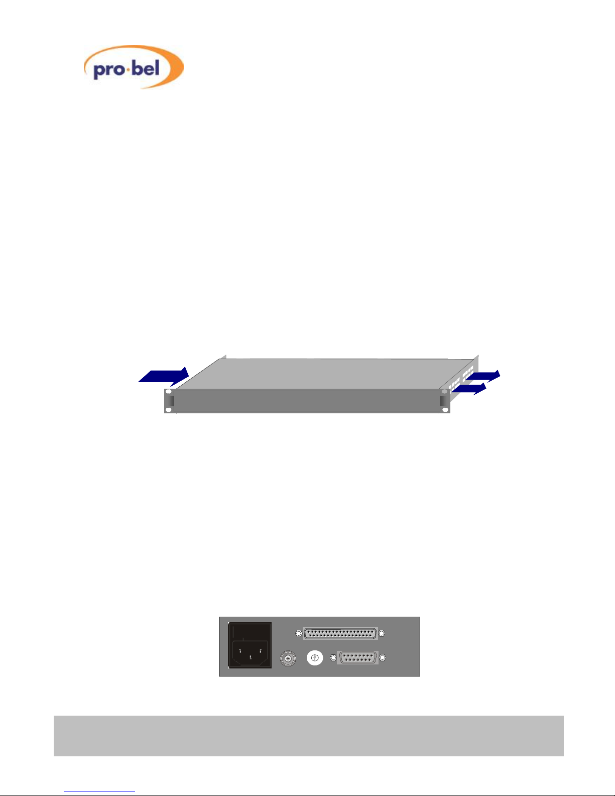
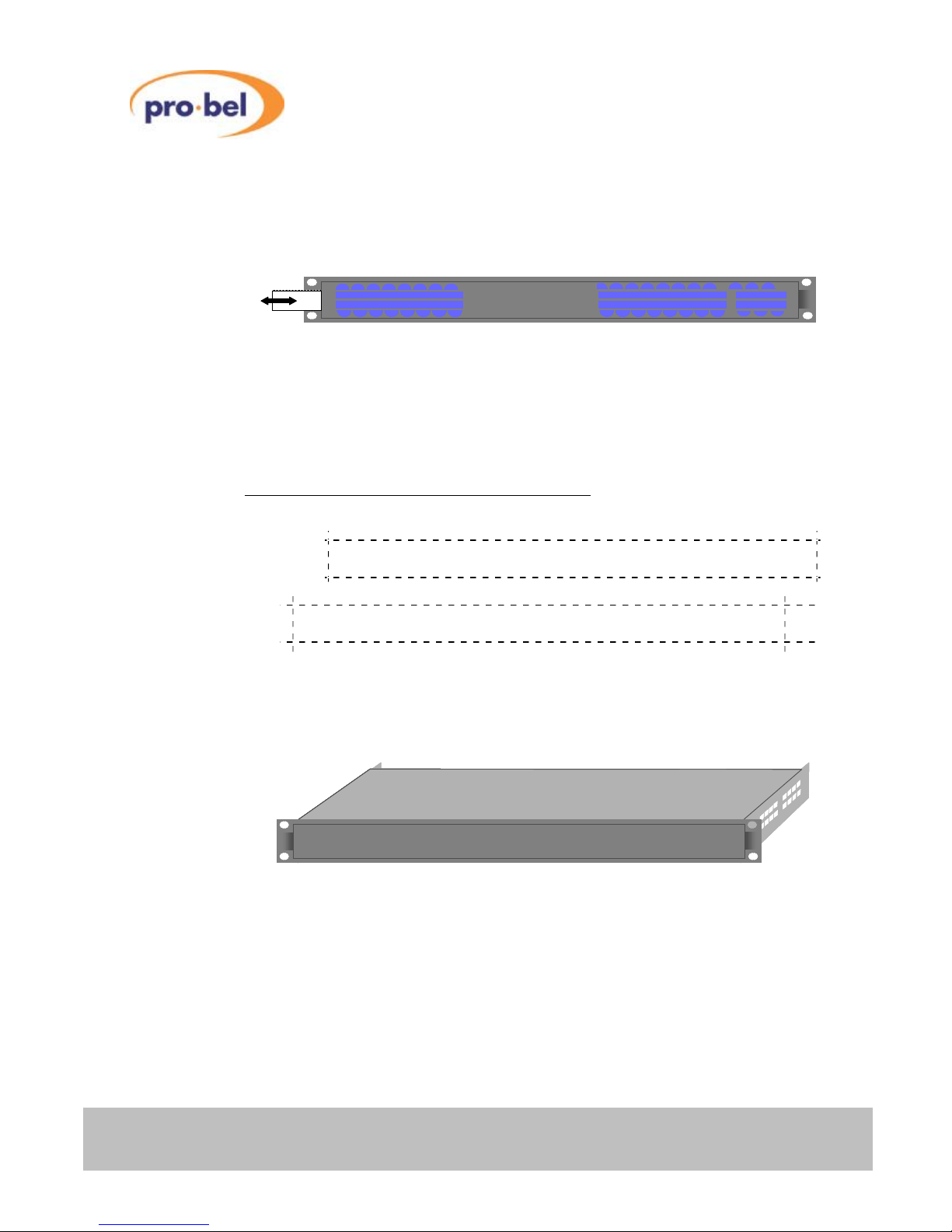
2.2 Ventilation
Each frame employs an internal fan assembly providing horizontal cross ventilation to
maintain a cool, internal, air temperature. Frames may therefore be mounted directly on top
of each other, or other equipment, without the need for vertical separation. Care should
however be taken when mounting frames directly above other equipment to ensure that
they are not subjected to excessive heat from that equipment, and that cooling vents in
equipment directly above or below them are not obstructed.
It is therefore essential during the installation process to observe the following points:
• Do not obstruct the vents on the unit to allow cooling to take place, allow at least
40mm free space on each side of the frame
• Ensure that both the fans and vents have access to the ambient temperature
room air
• Do not obstruct cooling vents in equipment directly above or below the frame.
Axis
Axis
Axis
Axis
Axis
Axis
Axis
Axis
Axis
Axis
Axis
Axis
Axis
Axis
Axis horizontal cross ventilation
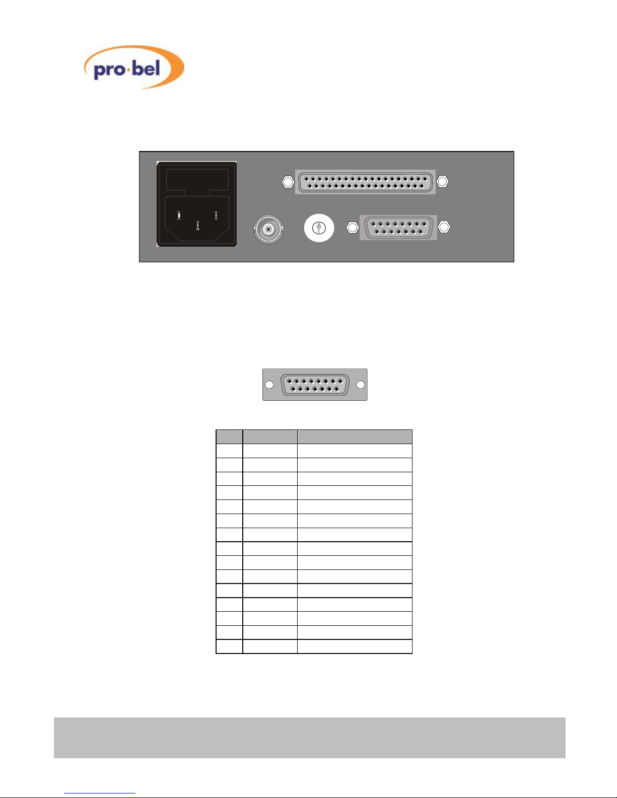
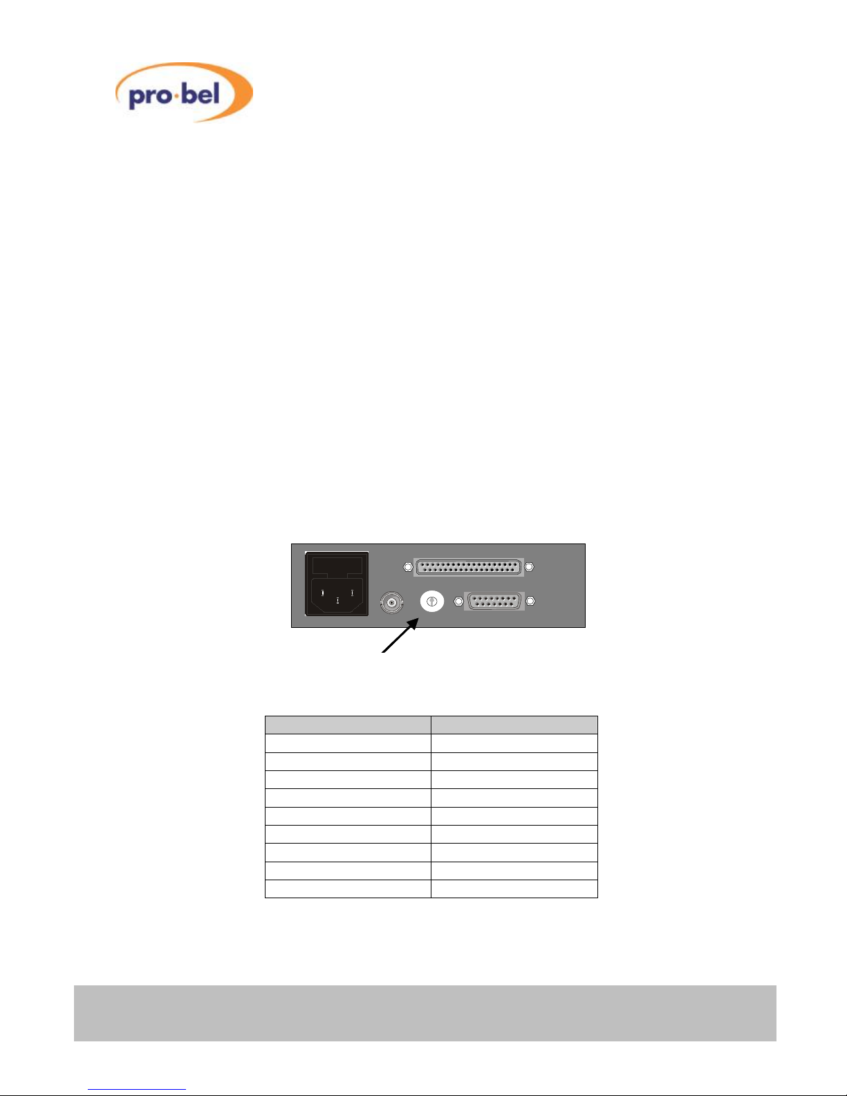
2.3 Power supplies
Axis frames are fitted with a single, auto-sensing, power supply unit and will operate from
mains voltages between 100 and 230 Vac, with frequencies of 47 to 63Hz. These PSU’s
automatically adapt to the supplied mains (line) input voltage, therefore no user adjustment
of the PSU is required
The mains (line) input to each Axis unit should be connected via the IEC connector fitted on
the rear of the frame at the left hand side. For additional safety, the IEC connector is fitted
with an integrated fuse holder.
SLAVE BUS
VID REF LEVEL CONTROL
1
2
0
8
3
4
5
6
7
9
A
B
C
D
E
F
1
2
0
8
3
4
5
6
7
9
A
B
C
D
E
F
SLAVE BUS
VID REF LEVEL CONTROL
1
2
0
8
3
4
5
6
7
9
A
B
C
D
E
F
1
2
0
8
3
4
5
6
7
9
A
B
C
D
E
F
HU-AXIS
7
AXIS user guide
For EMC and safety reasons the mains, chassis and signal earths are permanently
connected together within the frame.
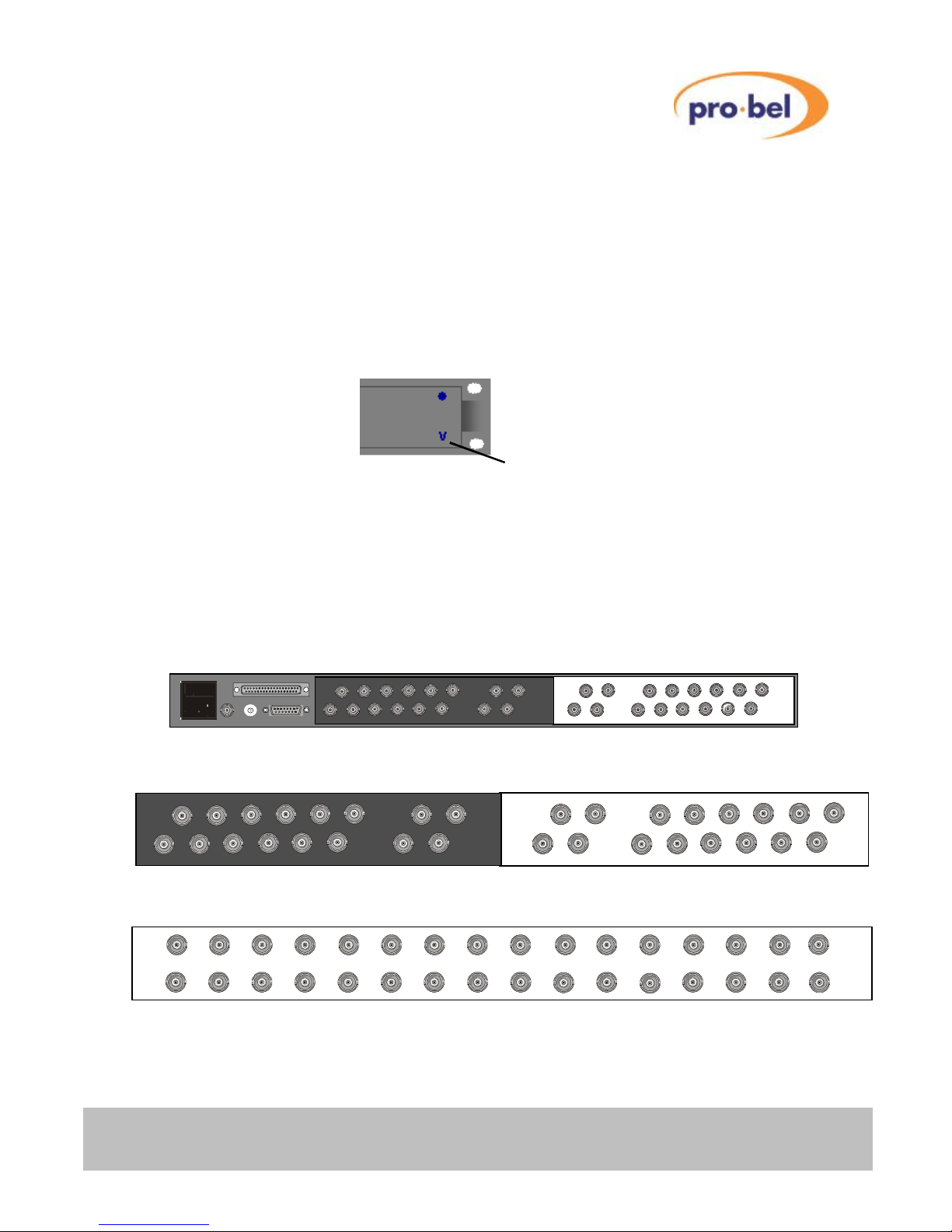
Axis slave frames, and Master frames without an integral panel, are fitted with a power
present LED (V) on the front panel indicating that power is present on the router module.
For systems fitted with an integral panel, the fact that the panel illuminates indicates that
power is present in the unit.
2.4 Signal connections
2.4.1 Analogue/ digital video, unbalanced digital audio and HD
digital video
Inputs
15 13 11 9 7 5 3 1
w
16 14 12 10 8 6 4 2
Inputs
w
Outputs
15 13 11 9 7 5
3 1
u
16 14 12 10 8 6
4 2
Outputs
u
Inputs
15 13 11 9 7 5 3 1
w
16 14 12 10 8 6 4 2
Inputs
w
Outputs
15 13 11 9 7 5
3 1
u
16 14 12 10 8 6
4 2
Outputs
u
SLAVE BUS
VID REF LEVEL CONTROL
Inputs 15 13 11 9 7 5 3 1
w
16 14 12 10 8 6 4 2
Inputs
w
Outputs 15 13 11 9 7 5 3 1
u
16 14 12 10 8 6 4 2
Outputs
u
1
2
0
8
3
4
5
6
7
9
A
B
C
D
E
F
1
2
0
8
3
4
5
6
7
9
A
B
C
D
E
F
SLAVE BUS
VID REF LEVEL CONTROL
Inputs 15 13 11 9 7 5 3 1
w
16 14 12 10 8 6 4 2
Inputs
w
Outputs 15 13 11 9 7 5 3 1
u
16 14 12 10 8 6 4 2
Outputs
u
1
2
0
8
3
4
5
6
7
9
A
B
C
D
E
F
1
2
0
8
3
4
5
6
7
9
A
B
C
D
E
F
Power present LED
Output
15
13
11 9
7
5
3
u
8
6
4
2
Output
u
15
13
16 15 14 13 12 11 10 9 8 7 6 5 4 3 2 1
Inputs Outputs
8 Issue 6
AXIS user guide
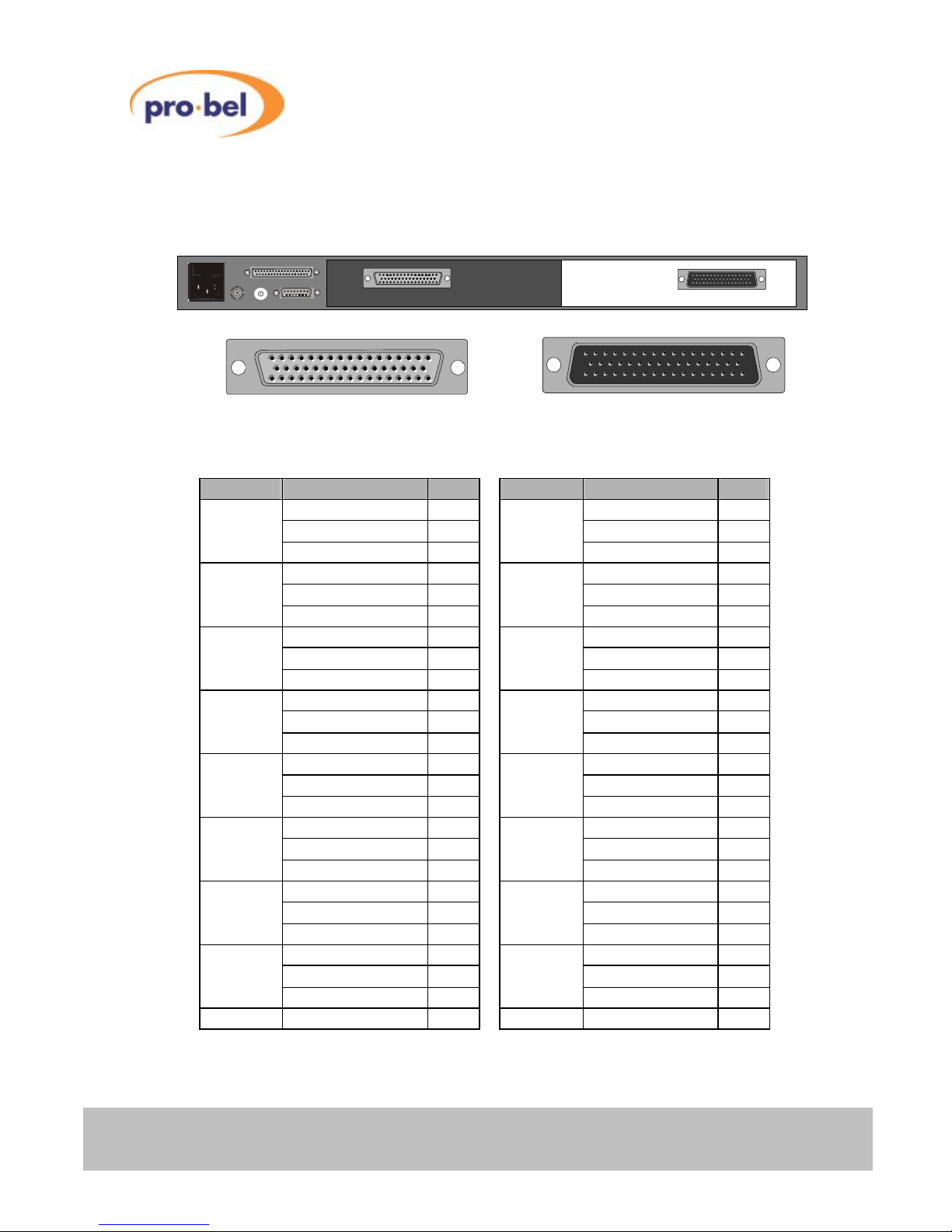
2.4.2 Digital audio (balanced) connector pinout
Output connector Input connector
50 way ‘D’ type socket (female) 50 way ‘D’ type plug (male)
Channel Function Pin Channel Function Pin
Signal + 18 Signal + 26
1
Signal −
2 9
Signal −
10
Signal GND 34 Signal GND 42
Signal + 35 Signal + 43
2
Signal −
19 10
Signal −
27
Signal GND 3 Signal GND 11
Signal + 20 Signal + 28
3
Signal −
4 11
Signal −
12
Signal GND 36 Signal GND 44
Signal + 37 Signal + 45
4
Signal −
21 12
Signal −
29
Signal GND 5 Signal GND 13
Signal + 22 Signal + 30
5
Signal −
6 13
Signal −
14
Signal GND 38 Signal GND 46
Signal + 39 Signal + 47
6
Signal −
23 14
Signal −
31
Signal GND 7 Signal GND 15
Signal + 24 Signal + 32
7
Signal −
8 15
Signal −
16
Signal GND 40 Signal GND 48
Signal + 41 Signal + 49
8
Signal −
25 16
Signal −
33
Signal GND 9 Signal GND 17
Screen Chassis GND 1 Screen Chassis GND 50
50 34 17 33 1 18 50 33 17 34 18 1
SLAVE BUS
VID REF LEVEL CONTROL
1
2
0
8
3
4
5
6
7
9
A
B
C
D
E
F
1
2
0
8
3
4
5
6
7
9
A
B
C
D
E
F
Outputs 1 –16 Inputs 1 –16
SLAVE BUS
VID REF LEVEL CONTROL
1
2
0
8
3
4
5
6
7
9
A
B
C
D
E
F
1
2
0
8
3
4
5
6
7
9
A
B
C
D
E
F
Outputs 1 –16 Inputs 1 –16
HU-AXIS
9
AXIS user guide
2.4.3 Analogue audio connector pinout
Output connector Input connector
50 way ‘D’ type socket (female) 50 way ‘D’ type plug (male)
Channel Function Pin Channel Function Pin
Signal + 18 Signal + 26
1L/9L
Signal −
2 5L/13L
Signal −
10
Signal GND 34 Signal GND 42
Signal + 35 Signal + 43
1R/9R
Signal −
19 5R/13R
Signal −
27
Signal GND 3 Signal GND 11
Signal + 20 Signal + 28
2L/10L
Signal −
4 6L/14L
Signal −
12
Signal GND 36 Signal GND 44
Signal + 37 Signal + 45
2R/10R
Signal −
21 6R/14R
Signal −
29
Signal GND 5 Signal GND 13
Signal + 22 Signal + 30
3L/11L
Signal −
6 7L/15L
Signal −
14
Signal GND 38 Signal GND 46
Signal + 39 Signal + 47
3R/11R
Signal −
23 7R/15R
Signal −
31
Signal GND 7 Signal GND 15
Signal + 24 Signal + 32
4L/12L
Signal −
8 8L/16L
Signal −
16
Signal GND 40 Signal GND 48
Signal + 41 Signal + 49
4R/12R
Signal −
25 8R/16R
Signal −
33
Signal GND 9 Signal GND 17
Screen Chassis GND 1 Screen Chassis GND 50
SLAVE BUS
VID REF LEVEL CONTROL
1
2
0
8
3
4
5
6
7
9
A
B
C
D
E
F
1
2
0
8
3
4
5
6
7
9
A
B
C
D
E
F
Outputs 9 –16 Outputs 1 –8 Inputs 9 –16 Inputs 1 –8
SLAVE BUS
VID REF LEVEL CONTROL
1
2
0
8
3
4
5
6
7
9
A
B
C
D
E
F
1
2
0
8
3
4
5
6
7
9
A
B
C
D
E
F
Outputs 9 –16 Outputs 1 –8 Inputs 9 –16 Inputs 1 –8
17 33 50 1 18 34 50 33 17 34 18 1
10 Issue 6
AXIS user guide
2.5 Control connections
2.5.1 Serial control connector
The control port is only active on Master Axis frames and, depending upon the database
option fitted, provides either two or three serial ports. The following table details the pin out
for the 15 way connector carrying these control connections.
15 way ‘D’ type socket (female)
Pin Function Port
1 GND
2 TX 1- RS 485 Port 1
3 RX 1+ RS 485 Port 1
4 TX 2- RS 485 Port 2
5 RX 2+ RS 485 Port 2
6 GND
7 TX RS232 Port 3 (Editor)*
8 RX RS232 Port 3 (Editor)*
9 GND
10 TX 1+ RS 485 Port 1
11 RX 1- RS 485 Port 1
12 TX 2+ RS 485 Port 2
13 RX 2- RS 485 Port 2
14 CTS RS232 Port 3 (Editor)*
15 RTS RS232 Port 3 (Editor)*
*The Editor port function is only available on Axis frames with the configurable database
option fitted.
SLAVE BUS
VID REF LEVEL CONTROL
1
2
0
8
3
4
5
6
7
9
A
B
C
D
E
F
1
2
0
8
3
4
5
6
7
9
A
B
C
D
E
F
SLAVE BUS
VID REF LEVEL CONTROL
1
2
0
8
3
4
5
6
7
9
A
B
C
D
E
F
1
2
0
8
3
4
5
6
7
9
A
B
C
D
E
F
8
15
1
9
HU-AXIS
11
AXIS user guide
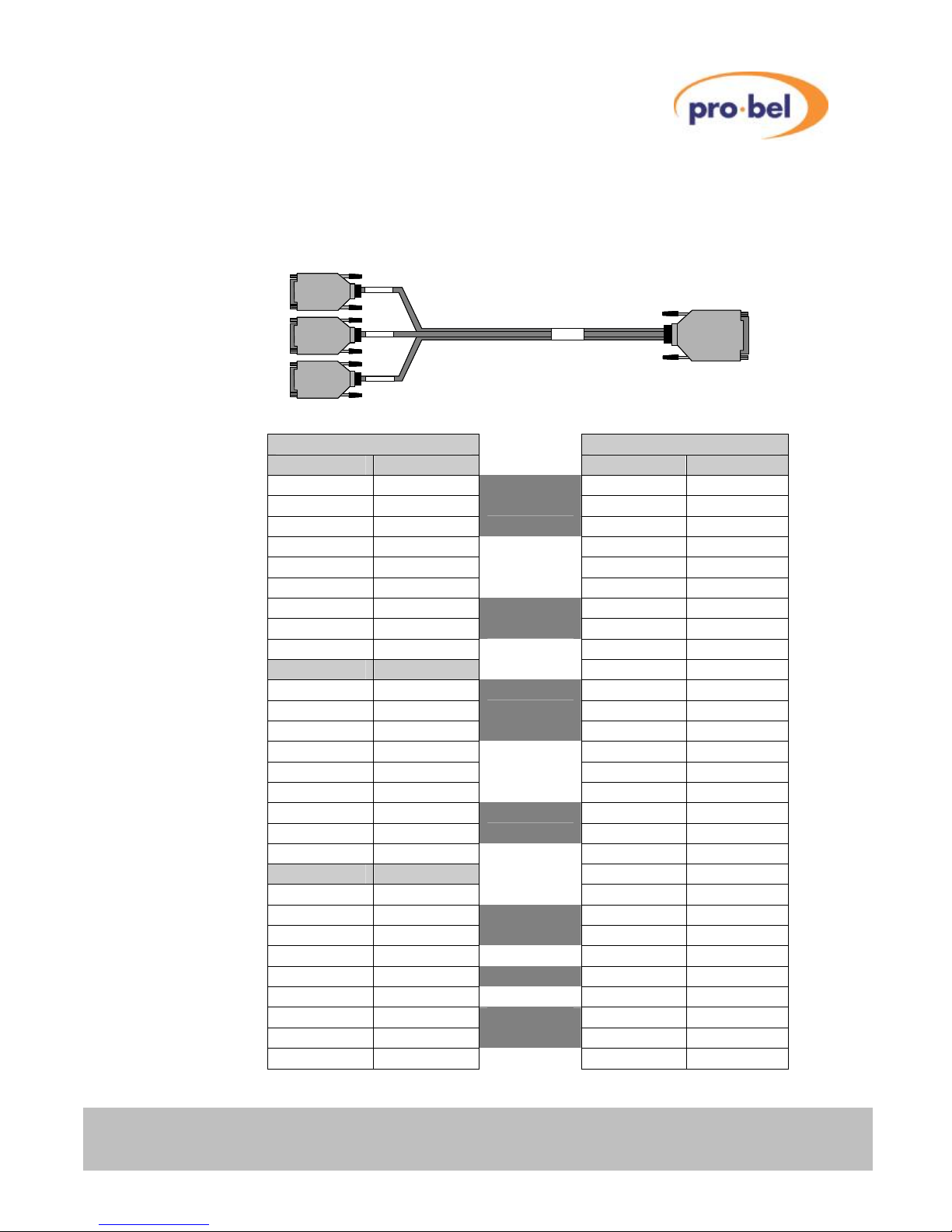
Each Master Axis frame is supplied with a 0.5 metre breakout cable, detailed below, to
facilitate easy connection to the system control ports. The cable permits Pro-Bel control
panels to be connected to the unit using a pin-to-pin cable.
9 Way Sockets 15 Way plug
Port 1 - Pin Function Pin Function
1 GND* 1 GND (Port 1)
2 TX – 2 TX – (Port 1)
3 RX + 3 RX + (Port 1)
4 GND*
5 N/C
6 GND*
7 TX + 10 TX + (Port 1)
8 RX – 11 RX – (Port 1)
9 GND*
Port 2 - Pin Function
1 GND* 9 GND (Port 2)
2 TX – 4 TX – (Port 2)
3 RX + 5 RX + (Port 2)
4 GND*
5 N/C
6 GND*
7 TX + 12 TX + (Port 2)
8 RX – 13 RX – (Port 2)
9 GND*
Port 3 - Pin Function
1 N/C
2 RX 7 TX
3 TX 8 RX
4 N/C
5 GND* 6 GND
6 N/C
7 RTS 14 CTS
8 CTS 15 RTS
9 N/C
*All GND pins are connected together inside the connectors or equipment.
RS485 PORT1 RS485 PORT2 RS232 PORT3
65433
- 1
15 way ‘D’ type
plug
3 x 9 way ‘D’
socket
RS48
Port
RS48
Port
RS23
Port
RS485 PORT1 RS485 PORT2 RS232 PORT3
65433
- 1
15 way ‘D’ type
plug
3 x 9 way ‘D’
socket
RS485 PORT1 RS485 PORT2 RS232 PORT3
65433
- 1
15 way ‘D’ type
plug
3 x 9 way ‘D’
socket
RS48
Port
RS48
Port
RS23
Port
12 Issue 6
AXIS user guide
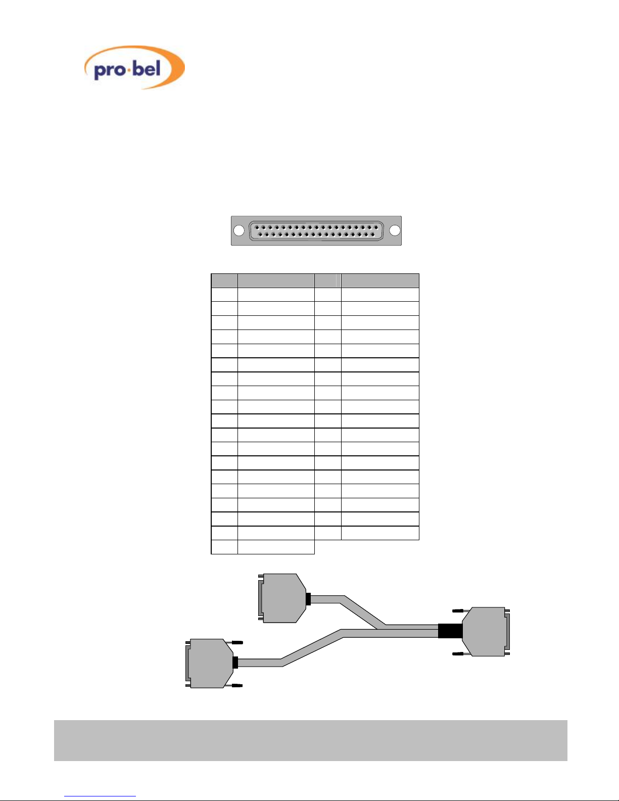
2.5.2 Parallel control connector
The Parallel control connector provided on both Master and Slave frames, labelled as
‘SLAVE BUS’, extends the internal crosspoint control bus to the rear of each frame. This
permits slave frames to be interconnected using the three way control cable (shown below)
supplied with them to construct multi-level routing switchers.
37 way ‘D’ type socket (female)
Pin Function Pin Function
1 Enable 20 H/Shake
2 Level A3 21 Level A2
3 Level A1 22 Level A0
4 Dest A6 23 Dest A5
5 Dest A4 24 Dest A3
6 Dest A2 25 DestA1
7 Dest A0 26 A6 Source
8 A5 Source 27 A4 Source
9 A3 Source 28 A2 Source
10 A1 Source 29 A0 Source
11 Aud 0 30 Aud 1
12 Aud 2 31 F/Sync
13 Strobe 32 N/C
14 N/C 33 N/C
15 N/C 34 N/C
16 N/C 35 N/C
17 N/C 36 N/C
18 N/C 37 Chassis
19 Chassis
SLAVE bus expansion cable
19
37
1
20
37 way ‘D’ type
plug (male)
37 way ‘D’ type
plug (male)
37 way ‘D’ type
socket (female)
37 way ‘D’ type
plug (male)
37 way ‘D’ type
plug (male)
37 way ‘D’ type
socket (female)

HU-AXIS
13
AXIS user guide
2.6 LED indicators
Slave frames, and Master frames without integral control panels are fitted with two front
mounted blue LED’s, one is a power present indicator and the other, a ’hello’ or handshake
indicator.
The power present LED indicates that power is present on the router module. Systems
fitted with an integral panel do not have these indicators, however the fact that the panel
illuminates indicates that power is present in the unit.
The ‘Hello’ LED is useful to determine whether the control system has spoken to, or can
‘see’ a particular router frame/ level. When the controller sends a command, for example in
response to a button push, the appropriate part of the router responds, depending on how
the level address switches are set. If all frames are set as level 1, the ‘Hello’ LED on every
frame will flash when a crosspoint command is sent from the controller in the master frame.
If however the router is set up as a multilevel system, and a crosspoint command is sent for
a route on one level – only that frame will respond.
2.7 Video reference
While every Axis frame is supplied with a terminating video reference input, it is only
necessary to provide a reference signal, ideally colour black or any stable analogue video
signal, to the Master frame within the system.
Because Axis routers can operate with signals of either 525/60 or 625/50 standards, the
video reference input automatically adapts to the standard of the reference applied to it.
From this signal, the controller housed in the Master unit generates a field pulse ‘strobe’
SLAVE BUS
VID REF LEVEL CONTROL
1
2
0
8
3
4
5
6
7
9
A
B
C
D
E
F
1
2
0
8
3
4
5
6
7
9
A
B
C
D
E
F
SLAVE BUS
VID REF LEVEL CONTROL
1
2
0
8
3
4
5
6
7
9
A
B
C
D
E
F
1
2
0
8
3
4
5
6
7
9
A
B
C
D
E
F
SLAVE BUS
VID REF LEVEL CONTROL
1
2
0
8
3
4
5
6
7
9
A
B
C
D
E
F
1
2
0
8
3
4
5
6
7
9
A
B
C
D
E
F
Power present LED
‘Hello’ handshake LED
14 Issue 6
AXIS user guide
which is fed to all slave frames in the system via the SLAVE BUS in order to ensure vertical
interval switching.
2.8 AES reference
There is no dedicated AES reference input, however the AES router derives its reference
from the signal present on input 1. For correct operation it is important that input 1 has a
valid AES signal present at all times.
2.9 Setting the level switches
Each Axis frame, whether it is a Master or Slave variant, must have its address set from the
rear panel.
In order to provide a system offering multilevel breakaway, each frame must have a unique
address. For routers where it is desirable to switch all levels at the same time, such as YUV
routers, the same address can be used across all three frames.
The following table details the switch setting required for each available level address.
Switch position Router level
0 Level 1
1 Level 2
2 Level 3
3 Level 4
4 Level 5*
5 Level 6*
6 Level 7*
7 Level 8*
8 to F Unused
* Levels 5 to 8 are only available in systems fitted with the editable database option.
SLAVE BUS
VID REF LEVEL CONTROL
1
2
0
8
3
4
5
6
7
9
A
B
C
D
E
F
1
2
0
8
3
4
5
6
7
9
A
B
C
D
E
F
SLAVE BUS
VID REF LEVEL CONTROL
1
2
0
8
3
4
5
6
7
9
A
B
C
D
E
F
1
2
0
8
3
4
5
6
7
9
A
B
C
D
E
F
Level address switch
SLAVE BUS
VID REF LEVEL CONTROL
1
2
0
8
3
4
5
6
7
9
A
B
C
D
E
F
1
2
0
8
3
4
5
6
7
9
A
B
C
D
E
F
SLAVE BUS
VID REF LEVEL CONTROL
1
2
0
8
3
4
5
6
7
9
A
B
C
D
E
F
1
2
0
8
3
4
5
6
7
9
A
B
C
D
E
F
Level address switchLevel address switch

HU-AXIS
15
AXIS user guide
3 Hardware configuration
3.1 Router details
3.1.1 Master frames
Master frames are supplied with an internal control module and are available with either a
fixed or editable database. This controller can be used either as a system controller,
providing control for a standalone Axis routing system with up to eight breakaway levels, or
to accept control from an external system controller allowing the frame to operate as a
standalone router.
The controller, offering extensive facilities, supports up to 32 panels or under monitor
displays with the editable database option. Axis supports the following panels from the
standard Pro-Bel panel range;
• 6276 X-Y
• 6277 multibus
• 6700 Series button panels
The system is further enhanced, by utilising the Freeway editor to provide extensive system
database configuration facilities. Editable features include; source/ destination names and
associations, programmable salvos, route inhibits, audio channel configurations and
joystick overrides. Full details of the Axis control system and database configuration can be
found in Chapters 4 to 6 of this user guide.
3.1.1.1 Integral control panel
Master frames can be supplied with an integral 16x16 X-Y control panel, enabling ‘plug and
play’ operation - straight from the box.
Axis
1 2 3 4 5 6 7 8 1 2 3 4 5 6 7 8 LVL1 LVL3 LOCK
9 10 11 12 13 14 15 16 9 10 11 12 13 14 15 16 LVL2 LVL4 PROT
SOURCES DESTINATIONS
Axis
1 2 3 4 5 6 7 8 1 2 3 4 5 6 7 8 LVL1 LVL3 LOCK
9 10 11 12 13 14 15 16 9 10 11 12 13 14 15 16 LVL2 LVL4 PROT
SOURCES DESTINATIONS
Axis
1 2 3 4 5 6 7 8 1 2 3 4 5 6 7 8 LVL1 LVL3 LOCK
9 10 11 12 13 14 15 16 9 10 11 12 13 14 15 16 LVL2 LVL4 PROT
SOURCES DESTINATIONS
Axis
1 2 3 4 5 6 7 8 1 2 3 4 5 6 7 8 LVL1 LVL3 LOCK
9 10 11 12 13 14 15 16 9 10 11 12 13 14 15 16 LVL2 LVL4 PROT
SOURCES DESTINATIONS
16 Issue 6
AXIS user guide
3.1.2 Inserting and removing the legend strip
The legend strip used in the integral X-Y control panel can be simply removed and replaced
by sliding it from underneath the front panel membrane from either end of the panel.
Replacement legend strips can easily be made using either a word processor or
spreadsheet, then printing onto transparent film using a laser printer. As the legend strip is
approximately 460mmx19mm, it may be necessary to make two shorter strips that can be
inserted from either end of the control panel (as shown below). A template for the panel
legend strip, in Microsoft Excel format, can be downloaded from the Pro-Bel website at
www.pro-bel.com/support/documentation/templates/6700 series BPX label strip.
3.1.3 Slave frames
Slave frames are fitted with a parallel control port enabling them to be connected to a
Master frame as part of a multilevel routing system. Because Axis frames utilise the same
control pin out as the Freeway control bus, they can also be connected to Freeway systems
and controlled as additional router levels.
1 2 3 4 5 6 7 8
9 10 11 12 13 14 15 16
1 2 3 4 5 6 7 8
Level 1 Level 3
9101112131415
16
Level 2 Level 4 Protect
#
#
1 2 3 4 5 6 7 8 1 2 3 4 5 6 7 8 LVL1 LVL3 LOCK
9 10 11 12 13 14 15 16 9 10 11 12 13 14 15 16 LVL2 LVL4 PROT
Axis
SOURCES DESTINATIONS
1 2 3 4 5 6 7 8 1 2 3 4 5 6 7 8 LVL1 LVL3 LOCK
9 10 11 12 13 14 15 16 9 10 11 12 13 14 15 16 LVL2 LVL4 PROT
Axis
SOURCES DESTINATIONS
Axis
Axis
Axis
Axis
Axis
Axis

HU-AXIS
17
AXIS user guide
3.2 System interconnections
3.2.1 Multilevel systems
Multilevel Axis systems can be constructed by interconnecting Slave frames to a Master
frame using the SLAVE bus expansion cable as shown in the diagram below.
While multilevel routers with up to eight independent breakaway levels can be built in this
way, it is possible to interconnect a maximum of twelve frames using this method. Typical
applications for systems built in this way could include YUV routers, where three video
levels can share the same level address making them permanently married.
3.2.2 Control panel interconnection
Pro-Bel’s range of standard control panels connect to the Master frame via an RS485,
multidrop control port. The control ‘break out’ cable supplied with Master frames, presents
the control port ready to simply connect to the panels using a simple pin-to-pin cable. Full
details of setting up control panels and their control connection pin outs can be found in the
relevant control panel handbook. Where an Axis frame is supplied with a front mounted
control panel, it forms an integral part of the Axis housing and therefore should not be
removed from the frame.
SLAVE BUS
VID REF LEVEL CONTROL
Inputs
15 13 11 9 7 5 3 1
w
16 14 12 10 8 6 4 2
Inputs
w
Outputs
15 13 11 9 7 5 3 1
u
16 14 12 10 8 6 4 2
Outputs
u
1
2
0
8
3
4
5
6
7
9
A
B
C
D
E
F12
0
8
3
4
5
6
7
9
A
B
C
D
E
F12
0
8
3
4
5
6
7
9
A
B
C
D
E
F12
0
8
3
4
5
6
7
9
A
B
C
D
E
F12
0
8
3
4
5
6
7
9
A
B
C
D
E
F
SLAVE BUS
VID REF LEVEL CONTROL
Inputs
15 13 11 9 7 5 3 1
w
16 14 12 10 8 6 4 2
Inputs
w
Outputs
15 13 11 9 7 5 3 1
u
16 14 12 10 8 6 4 2
Outputs
u
1
2
0
8
3
4
5
6
7
9
A
B
C
D
E
F12
0
8
3
4
5
6
7
9
A
B
C
D
E
F12
0
8
3
4
5
6
7
9
A
B
C
D
E
F
SLAVE BUS
VID REF LEVEL CONTROL
1
2
0
8
3
4
5
6
7
9
A
B
C
D
E
F12
0
8
3
4
5
6
7
9
A
B
C
D
E
F12
0
8
3
4
5
6
7
9
A
B
C
D
E
F12
0
8
3
4
5
6
7
9
A
B
C
D
E
F12
0
8
3
4
5
6
7
9
A
B
C
D
E
F
Outputs 1 –16 Inputs 1 –16
SLAVE BUS
VID REF LEVEL CONTROL
1
2
0
8
3
4
5
6
7
9
A
B
C
D
E
F12
0
8
3
4
5
6
7
9
A
B
C
D
E
F12
0
8
3
4
5
6
7
9
A
B
C
D
E
F12
0
8
3
4
5
6
7
9
A
B
C
D
E
F12
0
8
3
4
5
6
7
9
A
B
C
D
E
F
Outputs 1 –16 Inputs 1 –16
SLAVE BUS
VID REF LEVEL CONTROL
1
2
0
8
3
4
5
6
7
9
A
B
C
D
E
F
1
2
0
8
3
4
5
6
7
9
A
B
C
D
E
F
1
2
0
8
3
4
5
6
7
9
A
B
C
D
E
F
1
2
0
8
3
4
5
6
7
9
A
B
C
D
E
F
1
2
0
8
3
4
5
6
7
9
A
B
C
D
E
F
Outputs 1 –16 Inputs 1 –16
SLAVE BUS
VID REF LEVEL CONTROL
1
2
0
8
3
4
5
6
7
9
A
B
C
D
E
F
1
2
0
8
3
4
5
6
7
9
A
B
C
D
E
F
1
2
0
8
3
4
5
6
7
9
A
B
C
D
E
F
1
2
0
8
3
4
5
6
7
9
A
B
C
D
E
F
1
2
0
8
3
4
5
6
7
9
A
B
C
D
E
F
Outputs 1 –16 Inputs 1 –16

18 Issue 6
AXIS user guide
3.2.3 Other control options
Full control compatibility of the ‘SLAVE BUS’ with the Freeway, interframe, parallel control
bus and the use of Pro-Bel general switcher protocol on the remote control port, ensures
seamless operation of Axis frames with all Pro-Bel control systems.
Axis Slave frames may be used within Freeway routing systems, providing additional,
smaller router levels working alongside base router frames.
• Freeway/ Axis control interconnection
• Aurora/ Axis control interconnection
free wayfree way
AxisAxis
AxisAxis
Axis Slave frames
Freeway Base frame
Freeway interframe
control bus/ Axis
SLAVE BUS
interconnection
AxisAxis
AxisAxis
Axis Slave frames
RS 485
Aurora –System controller
(Hardware or Software based)
Axis Master frame
Axis
SLAVE BUS
AxisAxis

HU-AXIS
19
AXIS user guide
4 Fixed database systems
Systems supplied with a fixed database contain a single, non-editable, database. In these
systems, the editor port – port 3 is disabled and does not therefore permit any system
changes to be made. This section details the database settings and control panels that can
be used.
4.1 Database settings
The following table details the default settings for the database. It should be noted that the
maximum number of levels that can be independently controlled in this configuration is four.
The database within a fixed configuration system is pre-configured to permit operation as a
multi-level router. The system supports up to fifteen button per crosspoint panels, each
controlling a single, dedicated output; plus a master X-Y panel with access to all sources
and destinations. This X-Y panel can be either the integral – front mounted panel or a
discrete unit.
It is essential, in order for the system to function correctly, that each panel used on the
system should be configured with a unique address matching the one set for it in the
system database. This address, in the case of a fixed configuration system, corresponds to
the destination being controlled, where the panel set to address 1 controls destination 1;
address 2 controls destination 2 etc. right through to panel 15 with address 15. The
following table summarises the control panel types, their address, controlled destination(s),
the number of levels controllable and their name in the database.
Item Configuration details
Maximum number of levels 4
Maximum number of control panels 16 (including the integral panel if fitted)
Control ports 2 (1x Panel port and 1x Remote control port)
Route Inhibits None
Salvo’s None
Source Associations One to one across all levels
Destination Associations One to one across all levels
Trigger method per source With respect to the applied video reference
Source Audio parameters Not available
Destination Audio parameters Not available

20 Issue 6
AXIS user guide
Port 1 - Fixed database configuration
Panel
Address
Panel
Name
Panel type Controlled
Destinations
Controlled
Sources
Override
Sources
Controlled
Levels
1 PNL 1-1 6709-BPX 1 1 to 16 1 to 8 4
2 PNL 1-2 6709-BPX 2 1 to 16 1 to 8 4
3 PNL 1-3 6709-BPX 3 1 to 16 1 to 8 4
4 PNL 1-4 6709-BPX 4 1 to 16 1 to 8 4
5 PNL 1-5 6709-BPX 5 1 to 16 1 to 8 4
6 PNL 1-6 6709-BPX 6 1 to 16 1 to 8 4
7 PNL 1-7 6709-BPX 7 1 to 16 1 to 8 4
8 PNL 1-8 6709-BPX 8 1 to 16 1 to 8 4
9 PNL 1-9 6709-BPX 9 1 to 16 1 to 8 4
10 PNL 1-10 6709-BPX 10 1 to 16 1 to 8 4
11 PNL 1-11 6709-BPX 11 1 to 16 1 to 8 4
12 PNL 1-12 6709-BPX 12 1 to 16 1 to 8 4
13 PNL 1-13 6709-BPX 13 1 to 16 1 to 8 4
14 PNL 1-14 6709-BPX 14 1 to 16 1 to 8 4
15 PNL 1-15 6709-BPX 15 1 to 16 1 to 8 4
16 PNL 1-16
6707-X-Y*
1 to 16 1 to 16 None 4
* Only one X-Y panel (Type 6707) can be used with a fixed database system – this can be
either the front mounted panel or a discrete unit.
4.2 Panel details
Panels available for use in the fixed database system are limited to the 6709, sixteen way
button per crosspoint and the 6706, 16x16 X-Y versions. Full details for configuring these
panels can be found in the 6700 series control panel user guide, however it is important to
ensure that the panel is configured for both the correct control system and panel operation.
The following table details the switch settings required for each panel type to provide correct
operation with an Axis system.
Switch settings
Panel type Operation
1 2 3 4 5 6 7 8
6709 BPX BPX 0 0 N/U N/U 0 0 0 0
6707 16x16 XY X-Y 0 0 N/U N/U 0 1 1 1
In addition it is important to ensure that each control panel connected to the system has a

HU-AXIS
21
AXIS user guide
unique panel address set, that corresponds to the one required for that panel type in the
database.
4.3 Remote control options
Because Axis level types are entered into the database as Freeway 64 level types, the
destination offset for the next level when controlling the system remotely (using Pro-Bel
general switcher protocol - SW-P-02) is 64 and NOT 16.
LEVEL DEST RANGE SOURCE RANGE
1 0 to 15 0 to 15
2 64 to 80 0 to 15
3 128 to 143 0 to 15
4 196 to 211 0 to 15
5 256 to 271 0 to 15
6 320 to 335 0 to 15
7 384 to 399 0 to 15
8 448 to 463 0 to 15
4.4 Port definitions
Master Axis frames with fixed databases have 2 RS485 control ports available. Their
operation is defined as shown below:
• 1 x Remote control port using SW-P-02 Pro-Bel General Switcher Protocol1
• 1 x Device port for up to 16 control panels using SW-P-06 Multi-drop
Communications Protocol2
1
This protocol is described in section 3.4.2. below. Full details of the command set are
available on request from Pro-Bel.
2
This is a proprietary protocol, used by Pro-Bel control panels and under monitor displays.
4.4.1 Port characteristics
The characteristics for each port are defined in the table below:

22 Issue 6
AXIS user guide
Port Name Standard Protocol Baud
rate
Data
bits
Parity Stop
bits
Device port (port 1) RS485 SW-P-06 38400 8 N 1
Remote control (port 2) RS485 SW-P-02 38400 8 E 1
4.4.2 Pro-Bel General Switcher Protocol (SW-P-02)
Pro-Bel General Switcher Communication Protocol is a robust, asynchronous method of
controlling routing switchers. It is the preferred method of controlling Pro-Bel routers.
The normal electrical parameters of the interface are:
• RS485
• 8 bit data
• 1 stop bit
• EVEN parity
• 38.4K baud
However the interface can be set to operate with any common RS485 parameters.
The message format protocol is standard, and always conforms to the following format:
SOM COMMAND MESSAGE CHECKSUM
Where:
SOM = Start of message = FF Hex
COMMAND = Command byte, which also defines message length
MESSAGE = May be zero or more bytes
CHECKSUM = 7 bit, 2s compliment sum of command and message field
(msb=0)

HU-AXIS
23
AXIS user guide
5 Editable database systems
Axis systems utilise the Pro-Bel Router Editor to program the system database, and also
have the ability to provide many of the advanced operations available to Freeway systems,
such as audio modify for the analogue audio level. This section details pertinent points that
should be noted when configuring an Axis database.
5.1 Level types
The following table details the correct Freeway level type to use in the database editor for
each available Axis level.
AXIS level type Equivalent Freeway level type Audio Parameters Max. source
& dest size
Analogue Video 32/64 – Analogue Video N/A 16
SDV or HD 32/64 – SDV N/A 16
AES 32/64 – AES N/A 16
Analogue Audio 32/64 – Analogue Audio Disabled 16
Analogue Audio 32/64 – Analogue Audio Enabled 16
Dual – Analogue Video 32/64 Dual – Analogue Video N/A 8
Dual – SDV or HD 32/64 Dual – SDV N/A 8
Dual – AES 32/64 Dual – AES N/A 8
Dual – Analogue Audio 32/64 Dual – Analogue Audio Disabled 8
Dual – Analogue Audio 32/64 Dual – Analogue Audio Enabled 8
Quad – Analogue Video 32/64 Quad – Analogue Video N/A 4
Quad – SDV or HD 32/64 Quad – SDV N/A 4
Quad – AES 32/64 Quad – AES N/A 4
Quad – Analogue Audio 32/64 Quad – Analogue Audio Disabled 4
Quad – Analogue Audio 32/64 Quad – Analogue Audio Enabled 4
Triple – Analogue Video 32/64 Triple – Analogue Video N/A 5
Triple – SDV or HD 32/64 Triple – SDV N/A 5
Triple – AES 32/64 Triple – AES N/A 5
Triple – Analogue Audio 32/64 Triple – Analogue Audio Disabled 5
Triple – Analogue Audio 32/64 Triple – Analogue Audio Enabled 5

24 Issue 6
AXIS user guide
5.2 Panel details
This section details the functional and operational aspects of the panels supported by the
editable database version of Axis.
5.2.1 Supported Devices
The Panels and Undermonitor displays (UMD’s) supported by the editable database
version are listed below;
Part Number Description
RCP-100N-1600 6709, 16 way single bus control panel
RCP-100N-1616 6707, Dual 16 way button panel
6726-00 6276, X-Y control panel
6277-80 6277, 8 bus control panel
6277-60 6277, 6 bus control panel
6277-40 6277, 4 bus control panel
6277-20 6277, 2 bus control panel
6140 8 character UMD- Red
6141 8 character UMD- Green
6143 Dual 8 character UMD- Red
6144 Dual 8 character UMD- Green
Full details for configuring these panels can be found in the relevant control panel user
guide, however it is important to ensure that each panel is configured for both the correct
control system and panel operation. The following table details the switch settings required
for each panel type to provide correct operation with an Axis system.
Switch settings
Panel type Operation
1 2 3 4 5 6 7 8
6709 BPX 0 0 N/U N/U 0 0 0 0
6707 X-Y 0 0 N/U N/U 0 1 1 1
6276 X-Y
Up Up Up Down Down Down Down
*
6277 2 to 8 bus
Up Up Up Down Down Up Down
*
6140/1/3/4 UMD
Down Down Down Down Up Down Up Down
* Set switch 8 'Up' for panels with addresses in the range 1-15 and down for panels with
address 16.
In addition it is important to ensure that each control panel connected to the system has a
unique panel address set, that corresponds to the one required for that panel type in the

HU-AXIS
25
AXIS user guide
database.
5.2.2 General panel details
An Axis router can drive up to sixteen multi-dropped panels from each of the two RS485
General Remote ports.
Each panel on the same RS485 port must be set, according to its handbook, to have a
unique multi-drop address. For this port and address, the database should be configured (if
applicable) with the:
• Panel type
• Source keypad
• Destination keypad
• Controllable destination
• Controllable levels and brightness
• Override sources
• Panel name
5.2.3 Panel features
This section describes the various features encountered across the range of panel types.
5.2.3.1 Protect
The protect function prevents other control devices connected to Axis, including devices
attached to the remote ports, from setting crosspoints on a particular destination. Until the
destination has been unprotected by the device that protected it originally, or from the panel
designated as master.
Protect operates on the destination assigned to each level for the destination association
that was protected.
If a control device attached to the multi-drop device ports attempts to set crosspoints on a
protected destination then an error message will be displayed on control devices with
displays. See ‘Panels with displays’ section for display messages.
Setting a protected destination causes protect button LEDS on other BPX type panels to
flash - if they are assigned to the same destination.

26 Issue 6
AXIS user guide
5.2.3.2 Line-up
This is a continuous toggle of preset and program sources allowing easier alignment of
sources on a matrix level. Line-up of sources is selected as follows:
• Route source to be aligned to desired destination.
• Make sure the level of the sources to be aligned is the most significant active
level.
• Select reference source as the preset source.
• Press <LINE-UP> button on panel. The LED associated with the <LINE-UP>
button will light to show the <LINE-UP> button has been pressed.
• Press <TAKE> button of desired destination. The source routed will toggle
between the reference source and the source to be aligned.
• Line-up of sources on a destination is cancelled by pressing the <LINE-UP>
button again. This cancels line-up altogether on the control device.
• The source being aligned is returned as the source routed to the destination
being used and also the LED associated with the <LINE-UP> button will be
extinguished.
• Pressing another <TAKE> button on the same panel will cause the original
source to be routed to the previous destination and then start the line-up
sequence on the new destination.
N.B. All control devices will power-up with line-up inactive.
5.2.3.3 Decrement and increment
Each time the <DECREMENT> or <INCREMENT> button is pressed, the source or
destination association number selected, depending on the active keypad, is
decremented/incremented with the panel displays being updated accordingly. When
decrementing/incrementing source associations, only levels that are active are changed
with the most significant active level's source association as the association to change.
5.2.3.4 Alt-dest
Each time the <ALT-DEST> button is pressed, the panel changes control to the alternate
set of assigned destination associations. When the LED to the left of the <ALT-DEST>
button is illuminated, the panel is then controlling the second set of destination associations

HU-AXIS
27
AXIS user guide
assigned to the panel. This function is typically used with multi-output panels.
5.2.3.5 Dest-ident
The <DEST-IDENT> button is used to identify the destination associations assigned to the
<TAKE> buttons on multi-bus panels. Pressing and holding down the <DEST-IDENT>
button changes the ‘STATUS’ displays to show the 8 character name for the assigned
destination association for the current set of destination associations.
By pressing the <ALT-DEST> button, the other set of destinations can be identified by
pressing and holding the <DEST-IDENT> button again. This function is typically used with
multi-output panels.
5.2.3.6 Level buttons and controllable levels
A 'married' source refers to situations where, having selected or routed a source on one
level, a user would automatically expect other levels to be married to it (i.e. associated with
it). Level buttons allow the user to 'breakaway' selections from this marriage.
Each button operates in a toggle on/off manner with the level active indicated by an
illuminated button. Unless otherwise stated each button toggles the state of one level only.
Only levels that are controllable can be toggled on or off.
On occasions when more controllable levels are assigned to a panel than there are level
buttons then the last level button controls the excess levels, i.e. if the controllable levels for
a 4 level button panel were defined as 1, 2, 3, 4, 5, 6 then level 1 to 3 would be assigned to
first three level buttons respectively, and the fourth level button would control levels 4, 5 and
6.
Single levels or all levels can be turned off, if required, via the editor terminal.
5.2.3.7 Alt-lev
The Alternate level shift function is used on panels with only four level buttons, allowing
individual control of all eight levels. It operates in a toggle on/off manner with an LED used
to indicate the level shift - when the LED is off then levels 1 to 4 are controllable and when
the LED is on levels 5 to 8 are controllable.
The level shift function is button programmable on all panel types (BPX and X-Y). Any
source or destination button can be configured as a level shift button.

28 Issue 6
AXIS user guide
5.2.3.8 Clear
This key is used as a source preset or destination clear key and is generally assigned to the
bottom right key on a keypad.
5.2.3.9 Controllable destinations
This applies to X-Y panels only. The user can configure any destination association to be
controllable from a given X-Y type panel.
5.2.3.10 Destination buttons
Button per destination type keypads and dial up keypads (multiple button presses) are
available.
Pressing a destination button or a sequence of destination buttons selects a destination
association index, which references one destination per level. This gives the user the
opportunity to make selections on different destinations.
The pressed button will either illuminate if it has a valid associated destination association
index, or have alphanumeric displays to show the name of the selected destination
association.
On power-up no destination button is selected so all destination buttons are extinguished
and any destination displays on X-Y panels are blanked.
5.2.3.11 Source buttons
Button per source type keypads and dial up keypads are available.
Pressing a source button or a sequence of these buttons, routes sources on the active and
controllable levels only.
The source buttons on some panels are used to preselect sources not route them. These
panels have <TAKE> buttons to make the selections.
5.2.3.12 Panel swap mode
Panel Swap Mode is a panel assignable feature which swaps pre-select and source routed
on <TAKE>, otherwise the pre-select does not change.

HU-AXIS
29
AXIS user guide
5.2.3.13 Display AUD parameters
This is an assignable feature to the special function buttons on 6276 X-Y and 6277 multibus panels only. When enabled this feature displays source and destination AUD
parameters in the eighth character of the displays for the most significant stereo Analogue
Audio level in the system.
5.2.3.14 Configure AUD parameters
This is an assignable feature to the special function buttons on 6276 X-Y and 6277 multibus only. When enabled this feature allows pre-selection of destination AUD parameters for
stereo analogue audio levels. If panel is a Master 6276 X-Y then enabling this feature
allows AUD parameters to be assigned to sources and destinations and allows trigger type
to be assigned to sources. Enabling this feature automatically enables the ‘display AUD
parameters’ feature.
5.2.3.15 Override inputs
Some panels allow a number of override inputs to momentarily override the current source
routed to a destination with another source.
When all overrides are released the original source that was routed before any overrides
were activated is restored. Shorting an override input pin to 0V, activates the override.
Each override input can have any source assigned to it and can be assigned to operate on
any level.
If more than one override input is active on a panel, then the lowest number override will
take priority.
When a destination is overridden no other crosspoint can be set on that destination by any
means unless it is a higher priority override.
The maximum number of overrides available to any panel is 16.
5.2.3.16 Keyswitch input
6276 and 6277 panels have the software ability to accept a keyswitch input to inhibit the
<TAKE> and source keypads. The default condition is <TAKE> button enabled (keyswitch
on). If the keyswitch is disabled then the source ‘PRESET’ display indicates ‘ LOCKED ‘.
To disable the <TAKE> button and source keypad pin 1 of the AUX input on the rear of the
panel needs to be connected to 0V.

30 Issue 6
AXIS user guide
5.2.3.17 Making selections
'Crosspoint' selections (or routes) are made provided:
• The destination and source are valid for the level
• The destination is controllable
• The level is active and controllable
• The route is not inhibited
• Destination is not protected
• An override is not active on this destination unless the source is a higher priority
override
The router is recognised as present by the Axis control card.
5.2.3.18 Special Function Keys
6276 and 6277 type panels have 4 special function keys arranged in a vertical line of 4
buttons to the left of the source/dest keypad. These keys can each be assigned a different
function as illustrated in the example below. See individual panel types for special functions
supported.
Decrement Increment
Line-up Protect
Source/dest keypad

HU-AXIS
31
AXIS user guide
5.2.3.19 Keypads
There are 32 assignable button per source keypads each with 64 source buttons (this
allows each panel to have a different keypad) and 8 dial-up type source keypads for use on
8 character display panels.
There are 32 assignable button per destination keypads each with 36 destination buttons
(this allows each panel to have a different keypad) and 8 dial-up type destination keypads
for use on 8 character display panels.
The dial-up keypads allow a maximum of four button presses per source or destination
selection.
Dial-up keypads can be used on display panels that need to access more sources or
destinations than there are direct entry keys on the keypad. They can be assigned to the
panel instead of the default button per source/destination keypad.
There is also an AUD config keypad used to assign AUD parameters on a button per
parameter basis. It is used with 6276 and 6277 panels and is illustrated below. This keypad
will only be active if <CONFIG AUD> assigned to one of the special function keys.
Config keypad
Clear
525
625
Norm
L-R R-L
Swap
Mono

32 Issue 6
AXIS user guide
5.2.3.20 Panels with displays
These panels have alphanumeric displays for 8 character messages. The table below
defines warning messages used throughout the range.
Valid source selections are shown on ‘PRESET’ or ‘STATUS’ displays as defined by the
user. These will be shown as:
• ‘SSSSSSSS’ for 8 character.
• ‘PRESET’ warning messages are enclosed by ?....?
• ‘STATUS’ warning messages are enclosed by <....>
Message Explanation
‘<No Dst>’ No destination association selected
‘<No Src>’
No source selected because no destination assigned for any
level in destination association
‘<↓↓↓↓>’
No destination assigned in the selected destination association
on the most significant active level but there are destinations on
the lower levels
‘<↑↑↑↑>’
No destination assigned in the selected destination association
on the most significant active level but there are destinations on
the upper levels
‘<↑↑↓↓>’
No destination assigned in the selected destination association
on the most significant active level but there are destinations on
the upper and lower levels
‘?No Src?’
Source association with no sources on any level has been
selected
‘*LOCKED*’
Panel <TAKE> button and source buttons are disabled via
keyswitch input
‘**PROT**’
Source cannot be routed as destination is protected. After a few
seconds the panel name is displayed before reverting back to
showing the current source routed a few seconds later
‘PROTECT?’
When flashing indicates that destination will be protected on next
take

HU-AXIS
33
AXIS user guide
‘*OVRIDE*’
Source cannot be routed as destination has overridden source
routed. After a few seconds the name of the device responsible
for the overrride is displayed before reverting back to showing the
current source routed or preset a few seconds later.
‘ROUTE INH’
Source cannot be routed as route inhibited. Displayed in Preset
display
‘?↓↓↓↓?’
No source preselected on the most significant active level but
there are sources preselected on the lower levels
‘?↑↑↑↑?’
No source preselected on the most significant active level but
there are sources preselected on the upper levels
‘?↑↑↓↓?’
No source preselected on the most significant active level but
there are sources preselected on the higher and lower levels
‘SALVO’
Displayed in STATUS or IN-USE displays to indicate that a salvo
has been preselected.
‘NO XPT!’
Error message displayed in STATUS or IN-USE to indicate that a
crosspoint cannot be set as card not present.
‘LEV CON’
Error message displayed in STATUS or IN-USE to indicate that a
crosspoint was not made on a level because the level was not
controllable from that panel.
‘DST CON’
Error message displayed in STATUS or IN-USE to indicate that a
crosspoint was not made because the X-Y panel attempting to
set it is not allowed to control the destination.
The brightness of the displays on applicable panels may be changed by reconfiguring the
database. It is not possible to have different brightness levels for different displays on the
same panel.

34 Issue 6
AXIS user guide
The following table defines the AUD parameter symbols used on UMDS and panels with 8
character displays when the ‘display AUD parameters’ feature is enabled on a level.
Symbol Description
Space Indicates normal source or destination
Steady ‘S’ Indicates destination is Swapped
Steady ‘M’ Indicates destination is Mono
Flash ‘N’ and ‘?’ Normal destination pre-selected
Flash ‘S’ and ‘?’ Swapped destination pre-selected
Flash ‘M’ and ‘?’ Mono destination pre-selected
Flashing ‘L’ Left channel of source routed to both channels
Flashing ‘R’ Right channel of source routed to both channels
Flashing ‘S’ Left and right channels swapped
NRM or NRM? Source is Normal or pre-selected to be Normal
L-R or L-R? Source is L-R or pre-selected to be L-R
R-L or R-L? Source is R-L or pre-selected to be R-L.
SWP or SWP? Source L/R swapped or pre-selected to be L/R swapped
525 or 525? Source using 525 trigger or pre-selected to use 525
625 or 625? Source using 625 trigger or pre-selected to use 625
Steady ‘→’
No audio parameters on current most significant active level but
other levels configured with audio parameters.
Flashing ‘→’ with ‘?’
No audio parameters pre-selected on most significant active level
but other levels configured with audio parameter pre-selected.
TRG? No source pre-select on level thus unknown trigger.
AUP? No source pre-select on level thus unknown audio parameter.

HU-AXIS
35
AXIS user guide
5.2.4 Assigning Audio parameters from panels
This section details the operation of: the Normal 6276 X-Y; Generic Multi-Output and 6276
X-Y Master panels with regards to: assignment of audio parameters for Analogue Audio
sources and destinations; assignment of trigger type to sources.
The four special function buttons are assignable, however two new special function buttons
are required:-
• <DISPLAY AUDIO> enable/disable display of AUD parameter indication.
• <CONFIG AUDIO> enable/disable configuration of AUD parameters
Common rules
While ‘config AUD parameters’ is enabled then only AUD parameters can be pre-selected
(i.e. sources and destinations cannot be dialled up). Pressing <CLEAR>, while in this
mode, will result in the panel returning to its previous state.
If the ‘display audio parameters’ function is disabled then full 8 character names will be
displayed with no AUD parameter, even if the first level is Axis Analogue Audio.
Selecting ‘display audio’ function results in the 8th character of the displays showing the
AUD parameter assigned for the most significant active level.
Assuming ‘display audio parameters’ is enabled then:The 8th character in PRESET and STATUS displays is:-
• Steady (non-flashing) when source AUD parameter is NORMAL
• Flashing when source AUD parameter is NOT NORMAL, i.e. SWAP
8th character in PRESET window shows AUD parameter of the pre-selected source
displayed for the most significant active level in the system.
8th character in STATUS displays shows AUD parameter of combined source and
destination taken for the most significant active level.
8th character in DESTINATION displays shows the destination AUD parameter of the
destination displayed for the most significant active level in the system.
If <CONFIG AUDIO> pressed to enable configuration of AUD parameters and no buttons
are pressed within a 1 minute timeout period then this function is automatically disabled and
the panel is returned to its previous state.
Enabling configuration of audio parameters always results in ‘display audio parameters’
being enabled.
The 'N' character to denote Normal is only used in AUD parameter pre-selecting. Usually

36 Issue 6
AXIS user guide
8th character is left blank to denote Normal.
If pre-selected route is found to be inhibited (from either editable route inhibit table or
internal system inhibit table) then the destination AUD parameter pre-selected will be
thrown away.
If a route is protected then AUD parameters and trigger type cannot be changed.
5.2.4.1 Normal 6276 X-Y
Rules
Only Destination AUD parameters can be assigned from this panel type.
8th character in DESTINATION display is also used to show the pre-selected destination
AUD parameter when character alternating with '?'.
Enabling configuration of AUD parameters by pressing <CONFIG AUDIO> will always
result in selector LED being lit against DESTINATION display.
Operation 1
Press <DISPLAY AUDIO> to enable audio parameters to be displayed (optional).
Select DESTINATION display.
Dial up destination (e.g. VT 3)
Press <CONFIG AUDIO> (selector LED lit against DESTINATION display) followed by the
required AUD parameter. The pre-selected AUD parameter is displayed (flashing alternately
with '?') in the 8th character of the DESTINATION display.
Press <TAKE> to:-
• Assign AUD parameter to destination
• Update 8th character of DESTINATION display to indicate new AUD parameter
• Update 8th character of STATUS display with combined source and destination
AUD parameter.
• Auto cancel ‘config AUD parameters’ mode
Operation 2
Press <DISPLAY AUDIO> to enable audio parameters to be displayed (optional).
Select DESTINATION display (selector LED lit against DESTINATION display)
Dial up destination (e.g. VT 3)

HU-AXIS
37
AXIS user guide
Select PRESET display (selector LED lit against PRESET display)
Dial up a source (e.g. VT 7)
Press <CONFIG AUDIO> (selector LED lit against DESTINATION display) followed by an
AUD parameter. The pre-selected AUD parameter is displayed (flashing alternately with '?')
in the 8th character of the DESTINATION display.
Press <TAKE> to:-
• Assign AUD parameter to destination
• Update 8th character of DESTINATION display to indicate new AUD parameter
• Update 8th character of STATUS display with combined source and destination
AUD parameter
• Auto cancel ‘config AUD parameters’ mode
5.2.4.2 Generic multi-output panels
Rules
Only Destination AUD parameters can be assigned from this panel type.
When DEST-IDENT activated the 8th character in STATUS displays shows AUD parameter
of the destination for the most significant active level in the system.
8th character in PRESET display normally shows AUD parameter of the pre-selected
source displayed for the most significant active level in the system. It is also used to show
the pre-selected destination AUD parameter.
Operation 1
Press <DISPLAY AUDIO> to enable audio parameters to be displayed (optional).
Clear PRESET display.
Press <CONFIG AUDIO> and select an AUD parameter. An 8 character name is displayed
in the PRESET display to indicate destination AUD parameter pre-selected.
Press <TAKE> to:-
• Assign AUD parameter to destination
• Update 8th character of STATUS display with combined source and destination
AUD parameter
• Auto cancel ‘config AUD parameters’ mode and blank PRESET display

38 Issue 6
AXIS user guide
Operation 2
Press <DISPLAY AUDIO> to enable audio parameters to be displayed (optional).
Dial up source in PRESET display.
Press <CONFIG AUDIO> and select an AUD parameter. The pre-selected AUD parameter
is displayed (flashing alternately with '?') in the 8th character of the PRESET display.
Press <TAKE> to:-
• Assign AUD parameter to destination
• Update 8th character of STATUS display with combined source and destination
AUD parameter
• Revert to showing source AUD parameter in 8th character of PRESET display
• Auto cancel ‘config AUD parameters’ mode
5.2.4.3 Master 6276 X-Y panel
The operation of this panel is identical to that of a Normal 6276 X-Y panel but has the
option of being able to configure AUD parameters and trigger type for sources as well as
being able to unprotect destinations set from another panel if <PROTECT> assigned.
To assign AUD parameters and trigger type to sources:Press <DISPLAY AUDIO> to enable audio parameters to be displayed.
Dial up source in PRESET display.
Press <CONFIG AUDIO> (DESTINATION display selector LED lights).
Take
Clear
SRC/DEST
Select

HU-AXIS
39
AXIS user guide
Press <S/D SELECT> to select PRESET display. N.B. There must be a source selected in
the PRESET display before source AUD parameters can be changed.
DESTINATION display blanks and STATUS display shows 4 character name for trigger
type assigned and 4 character name for AUD parameter assigned to source.
Pre-set AUD parameter and/or trigger type. STATUS display shows 3 character ident for
trigger type and AUD parameter followed by '?' (e.g. ‘625 SWP?’ - trigger type to remain
unchanged but SWAP pre-selected as AUD parameter).
Press <TAKE> to:-
• Assign trigger type and AUD parameter to source
• Display new parameters in STATUS display for 2 seconds before reverting back
to displaying source routed in STATUS display and destination in DESTINATION
display.
auto cancel ‘config audio parameters’
5.3 Remote control options
Because Axis level types are entered into the database as Freeway 64 level types, the
destination offset for the next level when controlling the system remotely (using Pro-Bel
general switcher protocol - SW-P-02) is 64 and NOT 16.
LEVEL DEST RANGE SOURCE RANGE
1 0 to 15 0 to 15
2 64 to 80 0 to 15
3 128 to 143 0 to 15
4 196 to 211 0 to 15
5 256 to 271 0 to 15
6 320 to 335 0 to 15
7 384 to 399 0 to 15
8 448 to 463 0 to 15

40 Issue 6
AXIS user guide
5.4 Port definitions
Master Axis frames with configurable databases have 3 control ports available. These are
defined below:
• 2 x RS485 ports
• 1 x RS232 Editor port.
The database editor can configure each of the RS485 ports to support one of a number of
protocols from the following list:
• SW-P-02 General Switcher Protocol1
• SW-P-06 Multi-drop Communications Protocol2
• SW-P-08 General Remote Control Protocol1
1
These protocols are described in section 3.3.
2
This is a proprietary protocol, used by Pro-Bel control panels and under monitor displays.
5.4.1 Port characteristics
The characteristics for each port are defined in the table below:
Port Name Standard Protocol Baud
rate
Data
bits
Parity Stop
bits
Gen Remote 1 RS485 Configurable
Gen Remote 2 RS485 See Section 4.4
Editor/Config RS232 SW-P-08 38400 8 N 1
5.4.2 Pro-Bel General Switcher Protocol (SW-P-02)
Pro-Bel General Switcher Communication Protocol is a robust, asynchronous method of
controlling routing switchers. It is the preferred method of controlling Pro-Bel routers.
The normal electrical parameters of the interface are:
• RS485
• 8 bit data
• 1 stop bit
• EVEN parity
• 38.4K baud
However the interface can be set to operate with any common RS485 parameters.

HU-AXIS
41
AXIS user guide
The message format protocol is standard, and always conforms to the following format:
SOM COMMAND MESSAGE CHECKSUM
Where:
SOM = Start of message = FF Hex
COMMAND = Command byte, which also defines message length
MESSAGE = May be zero or more bytes
CHECKSUM = 7 bit, 2s compliment sum of command and message field
(msb=0)
5.4.3 Pro-Bel General Remote Control Protocol (SW-P-08)
This protocol has been developed to provide a common and robust method of interfacing
Pro-Bel control systems to a variety of standard and custom applications. It is the standard
protocol for interfacing a controller to a remote device.

42 Issue 6
AXIS user guide
6 Configuring the database
The following section describes the Axis control system. The control module supplied with
Master Units provides the interfaces, database and operating software required to configure
and control the Axis router family.
6.1 The Axis database editor
As described earlier in this guide, Axis uses the Freeway database editor program to edit
the system database. When installing this program, it will refer to Freeway rather than Axis.
6.1.1 Hardware requirements
Freeway Editors have been designed to run on the Microsoft Windows 95, or NT4
operating systems.
The editor and associated programs require around 3.2 Mbytes of hard drive space. Each
saved database typically requires 1.3 Mbytes.
To use the editor 'On-Line', the PC must have an RS 232 port capable of operating at 38.4
Kbaud.
6.1.2 Installing the Editors
The editor is supplied either on a CD ROM, Product number FRE-EDIT-WN32, or as an email attachment.
To install from CD;
Insert the CD ROM into the PC's CD drive and either,
Click 'Start', then select Run from the start menu, then type D:Setup (where D id the drive
letter for the CD ROM drive) and click OK, or
Run Explorer, view the contents of the CD ROM and select Setup.exe and follow the
instructions on screen.
An HTML help file is provided with the editor package and is installed at the same time as
the editors. A shortcut to these files can be found in the Start menu under Freeway Editor in
the Programs folder.

HU-AXIS
43
AXIS user guide
6.2 Understanding the database
The editable database, which is held in non-volatile RAM in the Axis control card,
determines the operation of the system and its associated panels.
To understand its use, a number of terms have to be defined:
• level - this term describes a type of router e.g. video or audio level.
• source - this term is used to describe an input of a router.
• destination - this term is used to describe an output of a router.
To configure a system the following parameters within the database must be considered:
• level type
• source and destination associations
• source names and destination association names
• route inhibit tables per level
• keypad and panel configuration
• general remote port configuration
• trigger method selection per source per level
• audio features per source per level
6.2.1 Level types
The level type within the Axis database defines the router type used on that level, permitting
advanced features such as audio parameters to be used. It also defines the shape of a
router level for example where it is used as a dual, triple or quad split for dual channel
audio, YUV or RGBS operation.
6.2.2 Source and destination associations
This is a method of setting a group of associated sources on different levels to a group of
associated destinations from a single button on a control panel. This is fundamental to the
operation of the database.
For example, a destination association defines the destinations on each level that feed into
a device, say a record VTR. Similarly, a source association defines the sources that
originate from a device, say a playback VTR. An association is assigned a unique number,
referred to as an index.
An example of this is:

44 Issue 6
AXIS user guide
Level Number
Dest Association Index 1 2 3 4 5 6 7 8
1 1 1 1 1 1 1 1 3
Destination index 1 defines a set of destinations, one for each level, that comprises - levels
1 - 7 as dest 1 and level 8 as dest 3.
Level Number
Source Association Index 1 2 3 4 5 6 7 8
3 4 4 3 3 3 3 1 1
Source index 3 defines a set of sources, one for each level, that comprises - levels 1 and 2
as source 4, levels 3 - 6 as source 3 and levels 7 and 8 as source 1.
Source and destination associations have different properties due to the distributive nature
of the router i.e. one source may feed to many destinations but a destination may only have
one source routed to it. One user may route the same source as another without affecting
each other. However, routing a source to the same destination as another user obviously
does affect each other. Therefore, a source association index may contain the same source
number on a given level as another index but a destination association index should
contain unique physical destination numbers. This avoids operational confusion as the
system does not check or prevent this condition.
A user may require one button to set the sources across all the levels and another button to
set only the audio sources. In order to do this special associations are used.
For example :
Level Number
Dest Association Index 1 2 3 4 5 6 7 8
65 - 1 1 1 - - - -
The level type assigned to level 1 is an Axis router that has 64 sources and 64 destinations.
Special Associations therefore start from source index 65, and can be used to assign extra
source combinations not defined in the standard association table, including those which
have no source associated with level 1. In the example above, source index 65 is used to
select source 1 from levels 2, 3 and 4 only. Special associations always start one index
number greater than the size of the fully equipped level 1 router for sources and
destinations.
Note: The normal associations i.e. 1-64 must contain source numbers for level 1,

HU-AXIS
45
AXIS user guide
corresponding to the association index numbers.
6.2.3 Source names
The Axis database allows the entry of 8 character alphanumeric names for each source on
each level, some panel types display these names when sources are preset and as
sources routed to a destination on selected levels.
6.2.4 Destination association names
Some control panels control more than one destination and have 8 character alphanumeric
displays to show the controllable destination. However, for space and operational reasons
there is only one display so that each destination association index can be assigned a
name and NOT each destination per level.
6.2.5 Route inhibits
This is a method of preventing sources from being set to certain destinations.
6.2.6 Salvos
Salvos are groups of crosspoints that are set altogether from a preset and take operation
on a control panel. A salvo is preselected and routed in a similar manner as normal
crosspoints.
6.2.7 Configuring source keypads
A keypad is a collection of buttons arranged on a panel. The database contains a number
of logical keypads that may be assigned to a physical keypad on a panel. Two types of
source keypads are available - button per source and dial-up keypads.
Button per source keypads operate in a single push to select a source association whilst
the dial up keypad allows a sequence of up to four button presses to select a source
association.
For example, the 6276 X-Y panel may have a dial up source keypad as follows:-
MON QC VTR CAM STUDO
TEST 7 BLACK 8 BARS
9
MAINT KEY EDIT 4
PBOX
5
HARRY
6
TX PGM PST
1
2
3

46 Issue 6
AXIS user guide
DAT SIL TONE
DEST
SRCE
0 CLEAR
Pressing <VTR> followed by <1> may select source VT1. Pressing <1> again may select
VT11. In this way, multiple button sequences can be used to select different sources.
Configuring a source keypad involves assigning a source association to a button or a
sequence of button presses.
6.2.8 Configuring destination keypad
Like the source keypads there are destination per button and dial up keypads. Configuring
a destination keypad involves assigning a destination association to a button with a
sequence of button presses.
6.2.9 Assigning panel types and keypads
This is a method of assigning different panel types and keypads to the sixteen panels on
each of the two ports.
6.2.10 Assigning source overrides
Some panels are equipped with joystick override inputs which, when pulled low, replace the
current source to a destination with a defined source. On releasing the override the original
source is restored.
6.2.11 Assigning controllable destination association indices
This is a method of setting which destination association indices can be controlled by a
given panel or a given port that uses a common keypad.
6.2.12 Assigning controllable levels/brightness
This is a method of setting the levels controllable from a given panel on a given port. In
addition, the brightness of the alphanumeric displays on some panels may also be
adjusted.
6.2.13 Configuring port characteristics
This is a method of setting the protocols and transmission characteristics of the RS485
General Remote ports and RS232 Remote Control port.
6.2.14 Audio features
This is a method to independently configure any audio source on any level to switch in one
of the following ways:
• Channel swap

HU-AXIS
47
AXIS user guide
• Left to both
• Right to both
• Summation

48 Issue 6
AXIS user guide
7 Trouble shooting
The following information is intended as a brief guide for diagnosing faults associated with
an Axis router.
It should be noted that Axis frames contain no user serviceable parts, therefore should this
product require servicing, you should refer to Pro-Bel or your local distributor.
The power LED on the front of the Axis router is off
• Check that mains is connected to the unit
• Check the fuse in the mains socket on the rear of the unit.
There is no communication with the Editor PC on the RS232 port?
• Check that the Axis unit has the editable database option fitted
• Check the power to the router
• Check that the router is receiving valid data from the controller - Either the
integral panel allows routes to be made or the ‘Hello’ LED on the front of the unit
flashes
• Ensure that PC is connected to the ‘EDITOR’ port on the ‘MASTER’ router
• Check cable interconnections
• Ensure that the electrical parameters of the serial port are set up correctly
• Check that the correct COM port is being used on the PC
There is no communication with external controllers on RS485 ports?
• Check power
• Ensure the router is receiving valid data from the controller - Either the integral
panel allows routes to be made or the ‘Hello’ LED on the front of the unit flashes
• Check cable interconnections
• Check electrical characteristics and protocol of controlling device are compatible
with that configured into the database

HU-AXIS
49
AXIS user guide
The control panels are in self test mode (button lamps sequencing)
• Check power to the router frame
• Ensure the router is receiving valid data from the controller - Either the integral
panel allows routes to be made or the ‘Hello’ LED on the front of the unit flashes
• Check that the port on the control card is configured in the database for
peripheral mode operation
• Check cable interconnections between the Master frame and the panels
The panel is communicating but there are no (or incorrect) responses
to button presses - panels not in self-test
• Check cable interconnections
• Check that the panel has been configured in the database as the correct type
• Ensure that each panel on the multidrop chain has a unique serial address
• Check that the panel configuration switches are set correctly
The panel controls the wrong destination
• Check that the panel is assigned correctly in database
• Check the panel is set to the correct address
The panel cannot select a crosspoint?
• Check database for:
panel assignment
level active
route not inhibited
no override active
level controllable
• Check router level address
The Master unit is switching but Slave levels are not following
• Ensure that the SLAVE bus cable is fitted correctly
• Check that the Master and Slave routers have unique level addresses (try setting
them the same and see if the routes are made)
• Check the database is set up for a multi-level system

50 Issue 6
AXIS user guide
8 Specification
8.1 General
8.1.1 Control
Fixed Configuration Master frames
RS485 ports: 2; 1 configured to drive one chain of 16 panels and 1
for external control
Parallel ports: 1, for control of slave AXIS router levels
Editable Configuration Master frames
RS485 ports: 2; independently configurable for either; driving chains
of 16 multidrop devices (panels/under monitor displays) OR for external
control
RS232 ports: 1; for system database configuration
Parallel ports 1; for control of slave AXIS routers
8.1.2 Power supplies
Supply: 90Vac to 240Vac auto sensing
Power: 20W nominal
8.1.3 General
Frame size: 1U x 19’ rack mounting x 340mm deep
Weight: 4Kg (typical)
8.1.4 Temperature range
Operating: 0°C to +40°C
Storage: -10°C to +70°C

HU-AXIS
51
AXIS user guide
8.2 Performance
8.2.1 Digital Video
Inputs
Number and type: 16 serial to EBU Tech 3276E, SMPTE 259M
Data rate: 140Mbit/s to 360Mbit/s
Impedance: 75Ω
Return Loss: >15dB 10MHz to 300MHz
Equalisation: 250 metres low loss video cable (typ. Belden
8281 or PSF 1 / 2)
Reference: Analogue video, 75Ω Terminating
Outputs
Number and type: 16 serial to EBU Tech 3276E, SMPTE 259M
Data rate: 140Mbit/s to 360Mbit/s
Impedance: 75Ω
Return Loss: >15dB 10MHz to 300MHz
Performance
Clock regeneration: On inputs
Reclocking: On outputs
Transition timing: 525 operation, Line 10; 625 operation, Line 6
8.2.2 HD/SD Digital Video
Inputs
Number and type: 16, to SMPTE 292M
Data rate: 140Mbit/s to 1.485GB/s
Equalisation: 100 metres Belden 1694A
Outputs
Number and type: 16 to SMPTE 292M, reclocked
or to SMPTE 259M, reclocked

52 Issue 6
AXIS user guide
8.2.3 Analogue video
Inputs
Number and type: 16, 1V p-p nominal, analogue video
Impedance: 75Ω
Return Loss: >46dB to 4.43MHz
Superimposed DC: ±2V maximum
Reference: Analogue video, 75Ω Terminating
Outputs
Number and type: 16, 1V p-p nominal, analogue video
Impedance: 75Ω
Return Loss: >36dB to 4.43MHz
Superimposed DC: ±30mV
Performance
Gain: 0dB ±0.05dB
Gain stability: <±0.05dB
Headroom: +3dB
Frequency response: ±0.1dB to 8MHz,
±0.15dB to 15MHz,
+0.25dB, -3dB to 30MHz
Differential phase: <0.1º
Differential gain: <0.1%
2T pulse/bar response: <0.2%K
50Hz squarewave tilt: <0.2%K
C/L gain inequality: <±0.5%
C/L delay inequality: <±0.5ns
Group delay variation: <2ns 50Hz to 15MHz
Crosstalk: -63dB (single adjacent)
-60dB (all hostile) @ 4.43MHz

HU-AXIS
53
AXIS user guide
8.2.4 Digital audio (Balanced and Unbalanced)
Inputs
Number and type: 16 serial to AES 3 - 1992
Impedance: 110Ω - balanced or 75Ω – unbalanced
Reference: Analogue video, 75Ω Terminating
Outputs
Number and type: 16 serial to AES 3 - 1992
Impedance: 110Ω - balanced or 75Ω – unbalanced
Performance
Re-clocking: On inputs
Path delay: 600ns (approx.)
Transparency: All paths totally transparent
8.2.5 Analogue audio
Inputs
Number and type: 16, electronically balanced, analogue audio
Impedance: >10kΩ balanced, 20Hz to 20kHz
Max level +24dBu
Outputs
Number and type: 16, electronically balanced, analogue audio
Impedance: <100 Ω
Max level +24dBu (not achievable into a 600Ω load)
Performance
Gain stability ± 0.1dB/24 hours
Frequency response ± 1dB 20Hz to 22kHz
THD + N < 0.1% at 1kHz, +18dBu
< 0.1% at 1kHz, 0dBu
Dynamic range >100dB: THD+N on -60dBFS tone referred to
full scale (AES17-1991)
Signal to noise ratio >100dB (gate operative)
Crosstalk <-90dB all hostile at 10kHz
Transients No audible clicks
 Loading...