

Page 1

Contents
1Introduction
2
2Installation
4
2.1Audio connector pin-out
5
2.2Installing DAC sub-boards
6
3Configuration 8
3.1Setting the operating mode 8
3.2Enabling the audio outputs 9
3.3Setting analogue output levels
10
4Trouble shooting
12
4.1Sample problems and their solutions 12
5Status monitoring 14
6Specification
16
7Ordering information
18
Technical Manual 1
4429SDI Audio Extractor
Page 2
1 Introduction
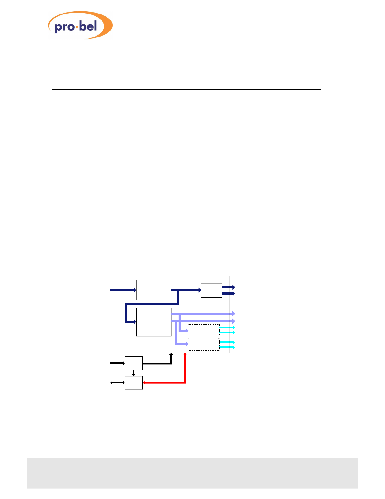
The 4429 extracts up to two dual channel digital audio signals embedded in a serial
digital component video signal. The basic card provides AES3 digital audio outputs
in both balanced and unbalanced formats. Up to two optional DAC sub-boards are
available, each providing electronically balanced programme quality analogue
outputs.
The 4429 automatically adjusts to handle audio embedded either continuously or to
SMPTE 272M. Equalised and regenerated copies of the digital video input are also
provided.
The module is designed to fit in the 1050 3U and 1051 1U Pro-Bel ICON modular
product rackframes.
Characteristics of the 4429 module are:
•
extracts two dual channel audio signals from an SDI input
•
balanced and unbalanced AES3 outputs
• high quality analogue outputs with one or two stereo DACs per module
•
handles synchronous or asynchronous embedded audio
• compatible with COSMOS, Pro-Bel status monitoring
2
chapter 1 Issue 1
4429
DC power and
status data
SDI with
embedded audio
SDI VIdeo with
embedded audio
buffered and reclocked
DIGITAL
AUDIO
EXTRACTOR
POWER
REG
STATUS
MON
REGENERATOR
OUTPUT
DRIVER
Optional DAC
Optional DAC
Two AES 3 serial
digital audio outputs
Analogue
audio outputs
Left 1
Left 2
Right 1
Right 2
AES 1
AES 2
The 4429 SDI Audio Extractor
Page 3

The 4429 module extracts digital audio signals embedded in a video signal fully
meeting the SMPTE 272M standard or the slightly different continuous format used
by Sony Betacam equipment. The module can extract any one of the four groups,
that is channels 1-4, 5-8, 9-12 or 13-16, but not combinations.
Technical Manual
chapter 1
3
4429SDI Audio Extractor
Page 4
2 Installation
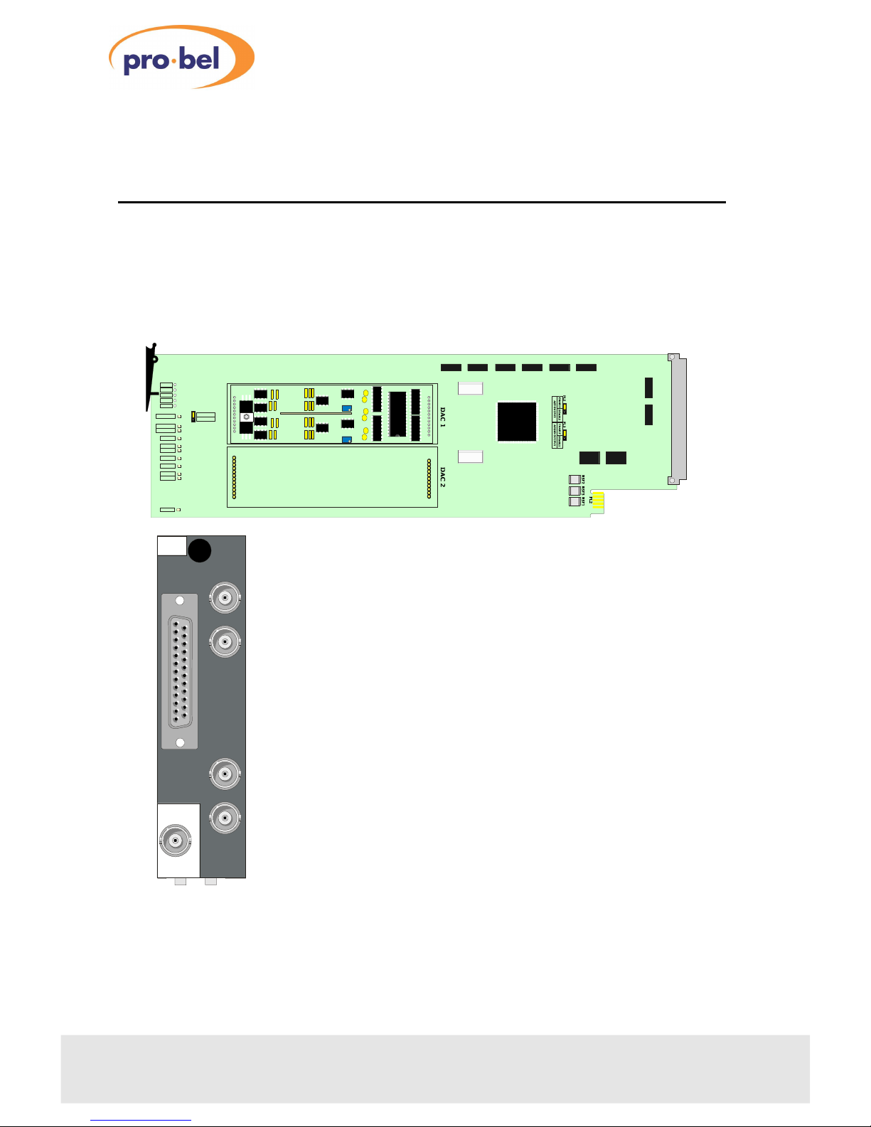
The audio extractor consists of a 4429 ICON module which uses the 30mm K4421.3
rear connector. There are five BNC connections for signal I/O and one 25 way ‘D’ type
female socket for the AES/EBU and analogue audio output. The 30mm rear
connector requires three slots in a 3U 1050 ICON frame and one module position in
the 1U 1051 ICON frame.
4
chapter 2 Issue 1
4429
AES OUT
SDI OUT
SDI
IN
AUDIO
K4421
(29)-3
SDI OUT
AES OUT
POWER
P
+12V
+5V
+15V
-15V
0V
REMOTE
LOCK 1
LOCK 2
4429
ADC 1
2
10
INIT
RA1
RA2
AD
VD
ER
RESET
TP14
TP5
TP6
TP7
TP4
LEFT
RV2
RIGHT
RV1
5635
P
LOCAL
REMOTE
Note: Please refer to the frame manual section for
module and rear connector installation assistance.
Page 5
2.1Audio connector pin-out
Technical Manual
chapter 2
5
4429SDI Audio Extractor
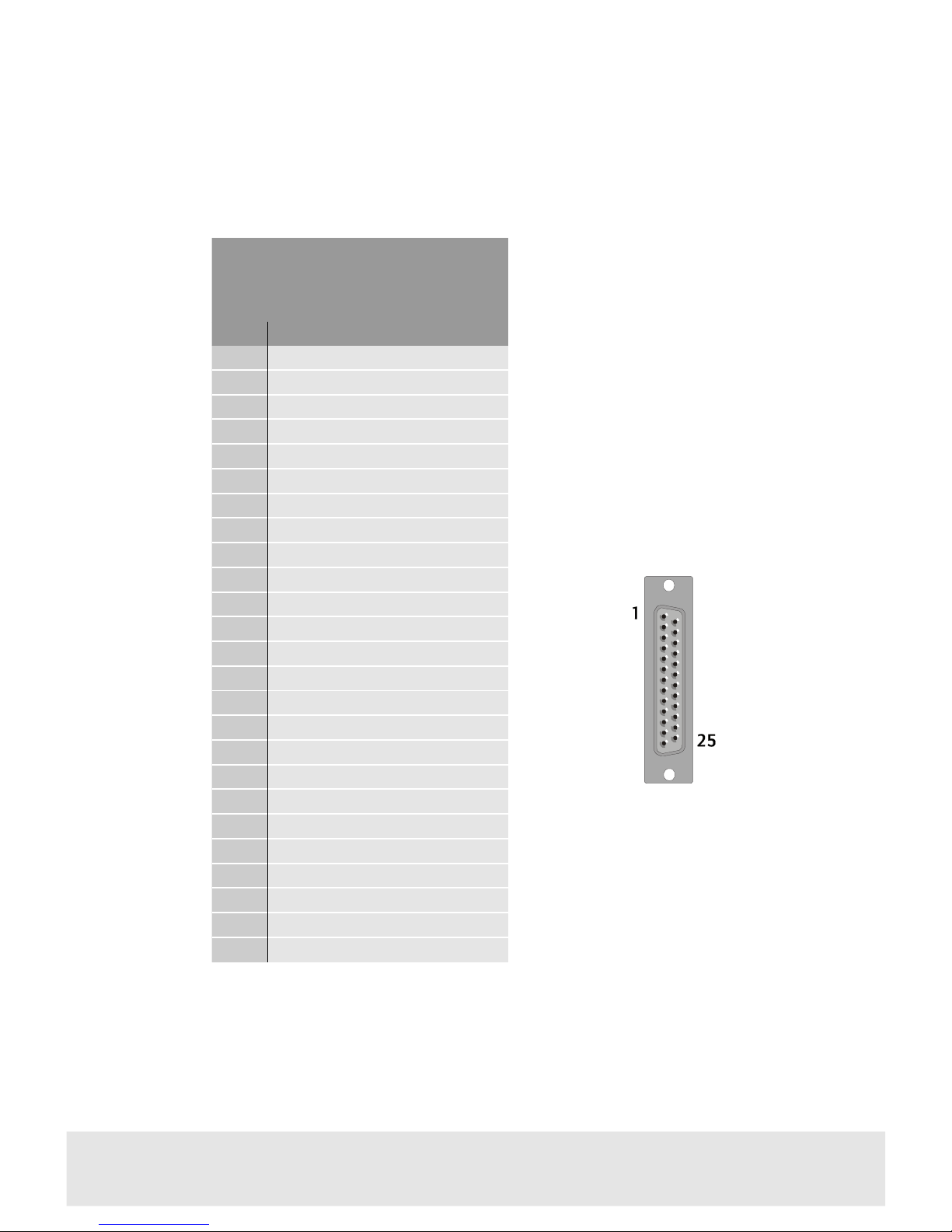
Audio output connector
25 way ‘D’ female socket
PinFunction
1
Analogue 1 - (AES 1A)
2
Analogue 1+ (AES 1A)
3
GROUND
4
Analogue 3 - (AES 2A)
5
Analogue 3+ (AES 2A)
6
GROUND
7
N/C
8
GROUND
9
N/C
10
N/C
11
GROUND
12
N/C
13
N/C
14
Analogue 2- (AES 1B)
15
Analogue 2+ (AES 1B)
16
GROUND
17
Analogue 4- (AES 2B)
18
Analogue 4+ (AES 2B)
19
N/C
20
GROUND
21
AES1-
22
AES1+
23
GROUND
24
AES2-
25
AES2+
Page 6
2.2Installing DAC sub-boards
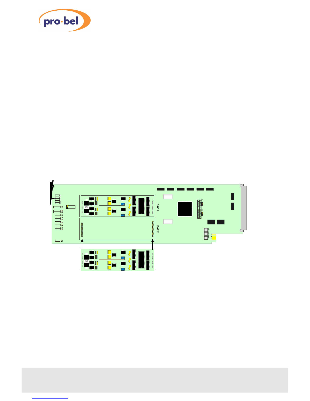
One or two 5635 DAC sub-boards can be fitted to the standard 4429 extractor at any
time to provide analogue audio outputs. DAC 1 provides analogue versions of the
first stereo pair, whilst DAC2 provides analogue versions of the second audio pair
from the selected group.
The converter should only fit one way round into the 4429 base module, since the
two header plugs are of slightly different sizes.
Proceed as follows:
• remove the 4429 base module from the frame
•
fit the converter(s) as shown in the diagram, taking care to line up the pins with
the base board headers
•
push the converter gently into its sockets, taking care not to bend any pins
•
re-insert the module into the frame
Note: Removal and insertion of the 4429 module may be done with the frame
powered
Note: In this drawing the silkscreen writing on the 5635 ADC sub-board is shown the
right way up for clarity. The actual board may have inverted text.
6
chapter 2 Issue 1
4429
Fitting a 5635 DAC sub-board
POWER
P
+12V
+5V
+15V
-15V
0V
REMOTE
LOCK 1
LOCK 2
4429
ADC 1
2
10
INIT
RA1
RA2
AD
VD
ER
RESET
TP14
TP5
TP6
TP7
TP4
LEFT
RV2
RIGHT
RV1
5635
P
LOCAL
REMOTE
LEFT
RV2
RIGHT
RV1
5635
P
11 pin connector12 pin connector
Page 7

Technical Manual
chapter 2
7
4429SDI Audio Extractor
Page 8
3 Configuration
3.1Setting the operating mode
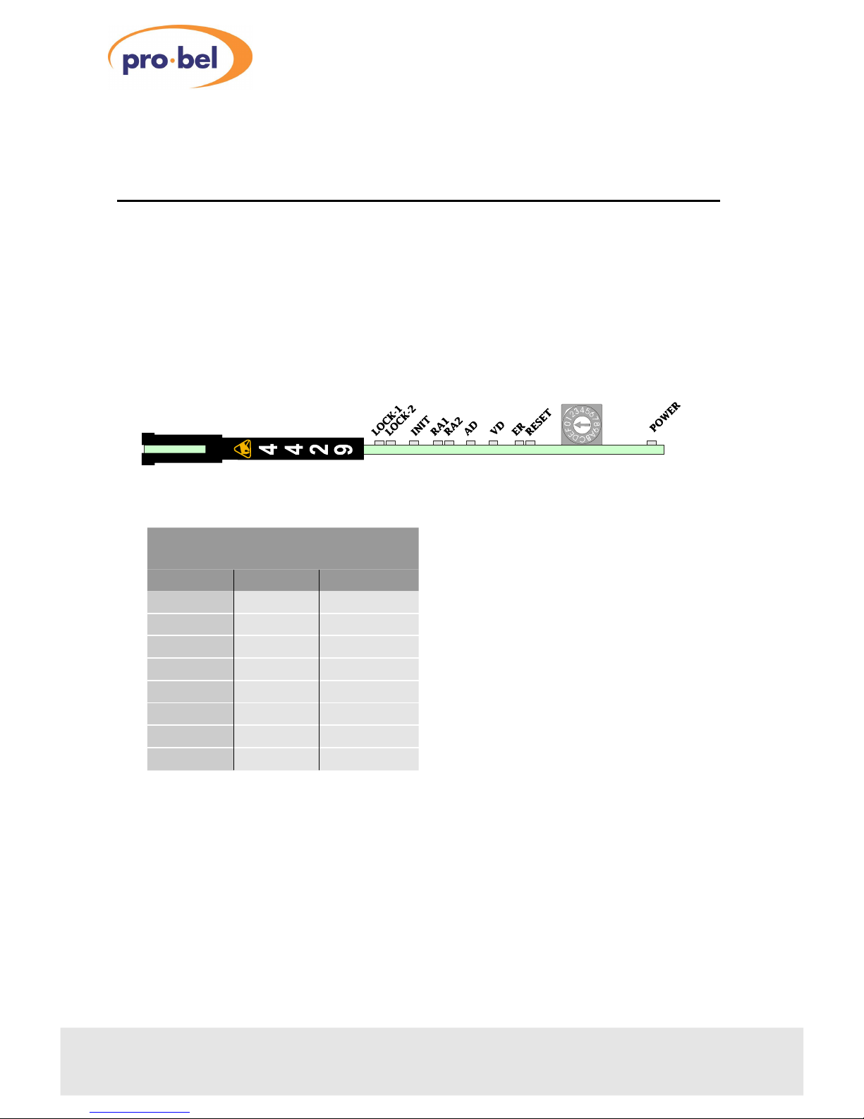
The rotary HEX switch, SW1, mounted on the front edge of the module sets the audio
group to be extracted as detailed in the table below. The asynchronous mode should
be used in situations where the embedded AES3 audio maybe unlocked.
Note: Each audio group selected can provide 2 stereo pairs or 4 mono signals. It is
not possible to select a stereo pair from one group and another stereo pair from a
different group. At any one time all audio outputs will originate from the same group
as selected by SW1.
8
chapter 3 Issue 1
4429
Hex switch settings
ModeGroupSync/Async
0
1Sync
1
2Sync
2
3Sync
3
4Sync
4
1Async
5
2Async
6
3Async
7
4Async
Page 9
3.2Enabling the audio outputs
AES output
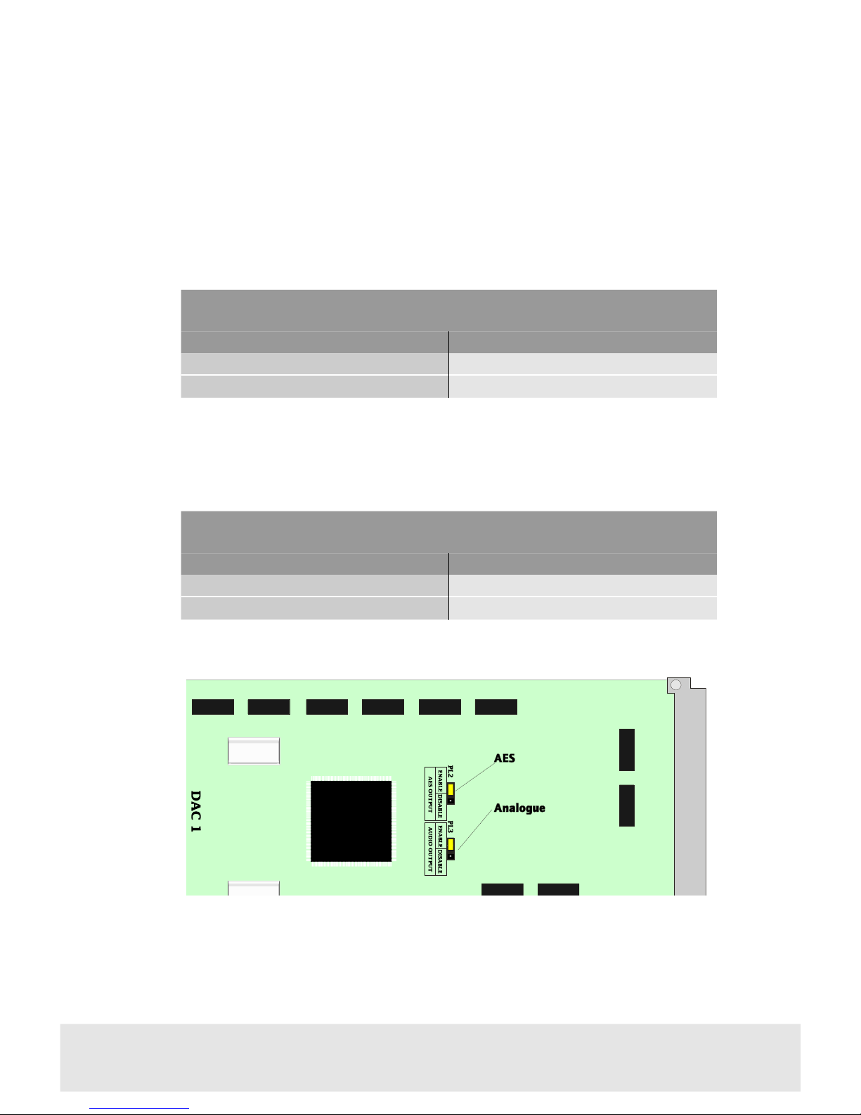
The AES output of the extractor maybe enabled/disabled by jumper PL2 and is
described in the following table.
Analogue Audio output
The audio output of the extractor may be enabled/disabled by jumper PL3 and is
described in the following table.
Technical Manual
chapter 3
9
4429SDI Audio Extractor
Enabling the AES output
PositionFunction
Enable
Enables the AES output
Disable
Disables the AES output
Enabling the analogue audio output
PositionFunction
Enable
Enables the analogue output
Disable
Disables the analogue output
Audio enable Jumper positions
Page 10
3.3Setting analogue output levels
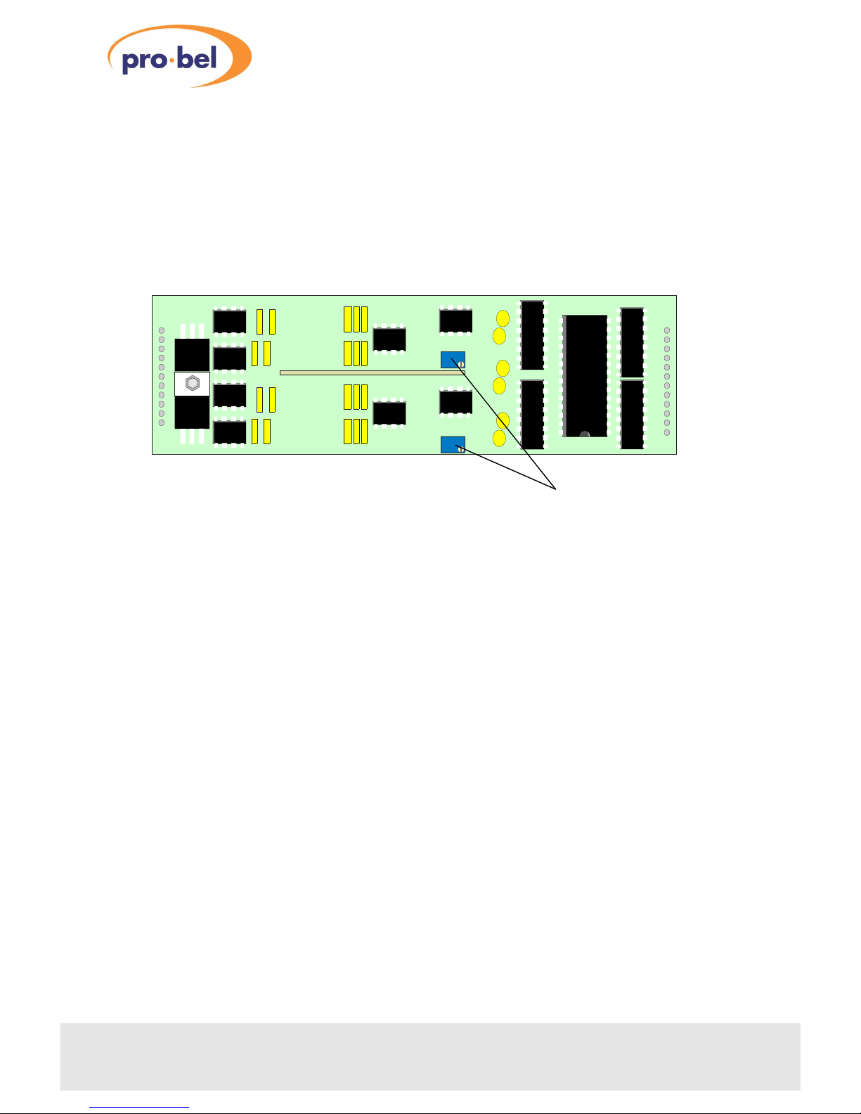
The analogue output levels of each 5635 DAC sub-module can be adjusted with RV1
for the right channel and RV2 for the left channel. The adjustment range is +15dBu
to +24dBu for Full Scale Digital (maximum digital word or clipping). Standard factory
setup is +18dBu=0dB, FSD for Europe and +24dBu=0dB, FSD for the US.
10
chapter 3 Issue 1
4429
LEFT
RV2
RIGHT
RV1
5635
P
Converter gain
Page 11

Technical Manual
chapter 3
11
4429SDI Audio Extractor
Page 12
4 Trouble shooting
Once configured, the module should not need further operational adjustments
unless signal or system requirements change. However, status LEDs are provided to
assist in the unlikely event that problems with configuration or module performance
arise.
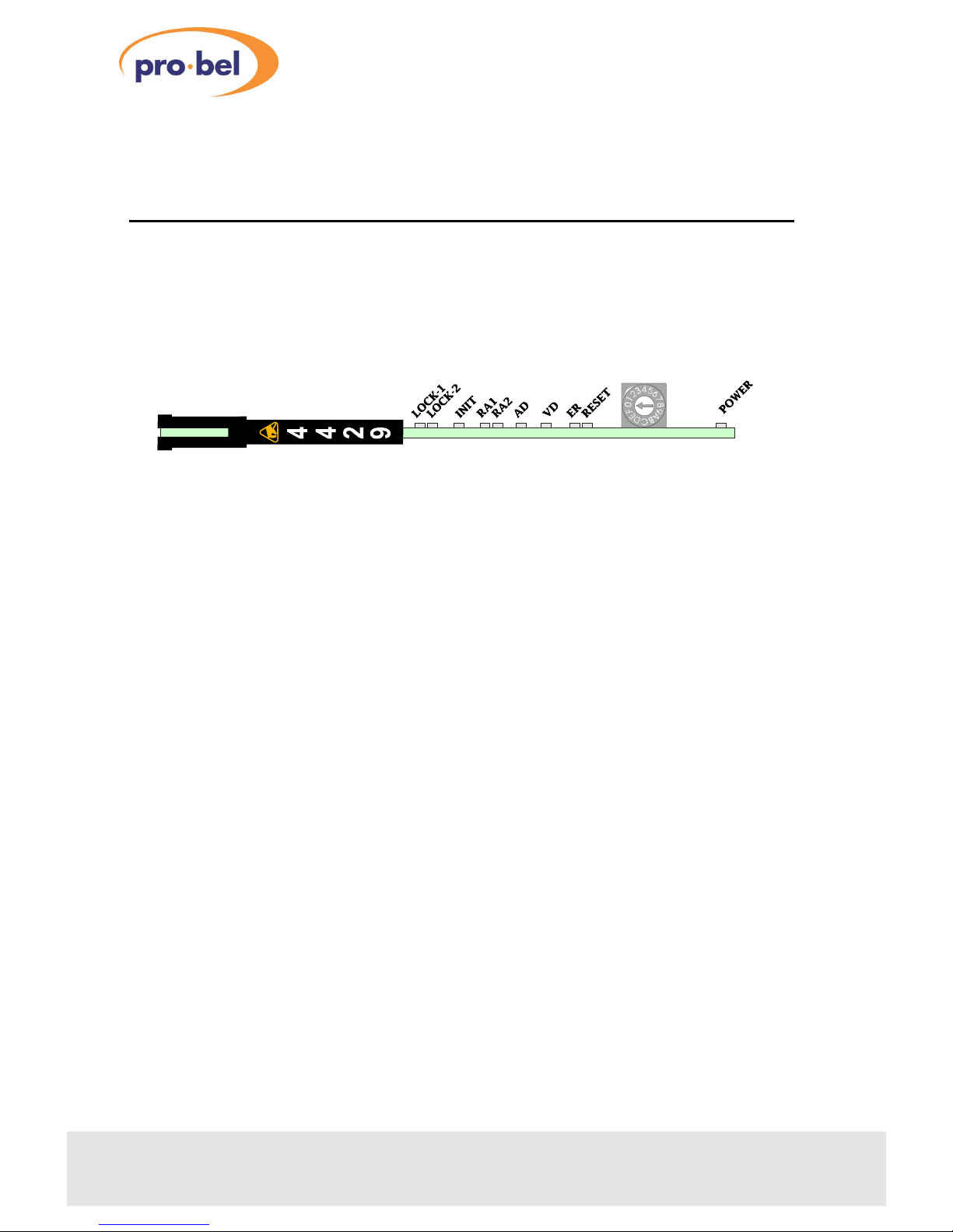
In normal operation the following green LEDs should be illuminated, VD, AD, RA1,
RA2, Lock1, Lock2 and Power. No red or yellow LED should be permanently lit, but
may flash briefly during power-up.
4.1Sample problems and their solutions
The green video present LED, VD is not illuminated
• check that the input cable is connected securely to the BNC socket on the rear
panel
• check that there is a digital video signal of the correct format connected
The red error LED, ER is illuminated
• if this red LED is on, then there is no video signal present
•
perform checks as for VD LED not illuminated
The green audio present LED, AD is not illuminated
• check that the input cable is connected securely to the BNC socket on the rear
panel
•
check that there is a digital video signal of the correct format connected
•
check Hex switch is set for correct mode of operation
12
chapter 4 Issue 1
4429
Page 13

The green read FIFO LEDs, RA1 and RA2 are not illuminated
•
RA1 and RA2 indicate the presence of either of the dual audio channels to be
extracted from the chosen group
•
if audio present LED, AD is lit, a module fault is indicated
The green lock LEDs, LOCK 1 and LOCK 2 are not illuminated
•
these LEDs monitor the output phase lock loops
• if only one audio channel is locked then only one LED will be illuminated
•
LEDs will not be illuminated when module is in asynchronous mode
The red reset LED, RESET stays illuminated
• there is a fault with the module, this LED should flash briefly on power-up
The yellow initialise LED, INIT stays illuminated
• there is a problem initialising the card, this LED should flash briefly on power-up
The green LED, POWER is not illuminated
•
check mains power to the frame is turned on
• if necessary check the PSU as explained in the power supply section
• check the card is plugged in securely
•
check to see if one of the resettable fuses has operated, perhaps after recent
servicing work on the board. To do this turn the power off, wait for thirty
seconds and then restore the power
Technical Manual
chapter 4
13
4429SDI Audio Extractor
Page 14

5 Status monitoring
The module will provide the following information to the status monitoring
controller, if fitted:
• module present
• video present
•
embedded audio present
• audio 1 PLL locked
•
audio 2 PLL locked
• DAC 1 fitted
•
DAC 2 fitted
•
AES output enable
• analogue output enable
•
local/remote mode
• power OK
In addition, the module is programmed with the following information, which can be
read by the status monitoring controller:
•
Module type
•
Module bar code
• Module issue no
In remote mode the following parameters can be controlled by COSMOS.
• group extracted
• synchronous/asynchronous mode
For further details of the Pro-Bel status monitoring system please refer to the
COSMOS status monitoring manual.
14
chapter 5 Issue 1
4429
Page 15

Technical Manual
chapter 5
15
4429SDI Audio Extractor
Page 16

6 Specification
Inputs
Video:One SDI to SMPTE 259M-C (270Mb/s)with
embedded audio to SMPTE 272M level A (locked
48kHz) or level D (unlocked 48kHz). Fully
compliant or embedded on all lines.
Impedance:
75W
Return Loss:>15dB, 10MHz to 300MHz
Equalisation:Up to 200m Belden 8281, PSF1/2 or equivalent
Outputs
Video:Two, SDI as input, equalised and reclocked
Impedance:
75W
Return Loss:>15dB, 10MHz to 300MHz
Digital Audio:
Two, balanced, 110W, to AES3-1992 and
unbalanced, 75W to AES3-id
Sample Rate:48kHz
Analogue Audio:One or two stereo pairs, balanced
Full Scale Level:+15dBu, +18dBu or +24dBu
Noise (typ, +18dBu peak):-86 dBu quasi peak, CCIR 468-2 weighted
-96 dBu rms, DIN audio band
On card controls/Indicators
Group extracted
Synchronous/asynchronous mode
AES output enable
Analogue output enable
Set analogue output levels (up to four)
Temperature range
Operating:
0° to +40°C
Storage:
-10° to +70°C
16
chapter 6 Issue 1
4429
Page 17

Technical Manual
chapter 6
17
4429SDI Audio Extractor
Page 18

7 Ordering information
Part numberDescription
ICO-4429-3xyzSDI Audio Extractor, 30mm
Where x =
yz =
number of stereo D to A converters fitted
0 (none) , S (single), D (dual)
analogue output level in dBu for full scale
digital 15, 18, or 24 ( 00 if no DACs fitted)
18
chapter 7 Issue 1
4429
 Loading...