

Page 1

Contents
1Introduction
2
2Installation
4
2.1Selecting a rear connector
4
3Configuration
6
3.1Configuring AES inputs 6
3.2Setting analogue output levels 7
4Trouble shooting
8
5COSMOS Status Monitoring 10
6Specification 12
7Ordering information
14
44111
Technical Manual
Page 2
1 Introduction
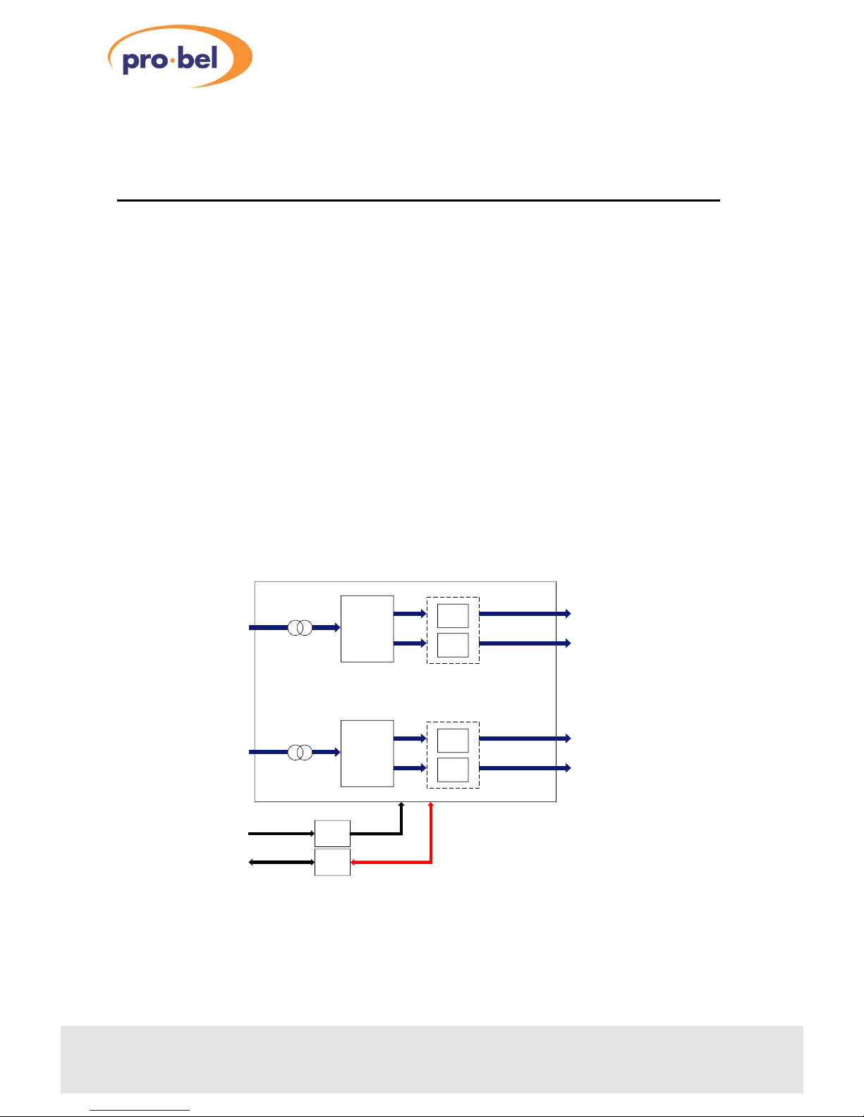
The 4411 module is an audio digital to analogue converter which may be fitted with
one or two stereo DAC sub-boards, each providing electronically balanced analogue
outputs from balanced or unbalanced digital inputs.
Two rear connectors are available depending on the choice of balanced or
unbalanced digital I/O. The module is designed to fit in the 1050 3U and 1051 1U
Pro-Bel ICON modular product rackframes.
Characteristics of the 4411 module are:
• one or two stereo DACs per module
•
balanced or unblanced AES inputs
•
full 20 bit conversion
• electronically balanced outputs
•
conversion gain to match EBU or SMPTE levels
•
sample rate 32kHz to 54kHz (continuous)
• compatible with COSMOS, Pro-Bel status monitoring
2
Issue 1
Audio Digital to Analogue Converter
DC POWER
AND COSMOS
STATUS DATA
POWER
REG
STATUS
MON
AES/EBU
INPUT 1
ANALOGUE
AUDIO
OUTPUTS
DAC
DAC
AES/EBU
DE-MUX
L1
R1
DAC
DAC
AES/EBU
DE-MUX
L2
R2
AES/EBU
INPUT 2
ANALOGUE
AUDIO
OUTPUTS
The 4410 audio analogue to digital converter
Page 3

44113
Technical Manual
Page 4
2 Installation
For module installation instructions please refer to the appropriate ICON rack frame
section of the manual
2.1Selecting a rear connector
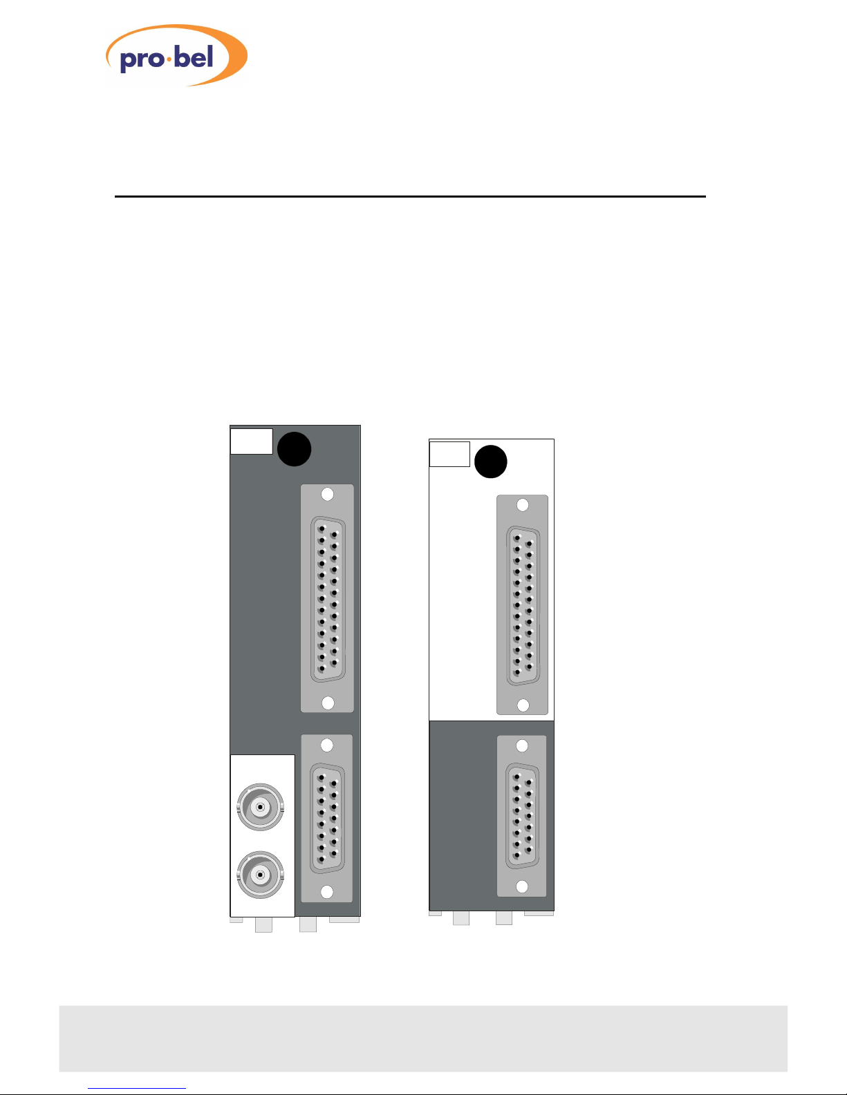
There are two alternative rear connectors available. The K4411.3B is used for
balanced signals, whilst the K4411.3U is used for unbalanced signals. Both occupy
30mm of rack width in the 1050 3U Icon rack frame or 1 slot in the 1051 1U rack
frame.
4
Issue 1
Audio Digital to Analogue Converter
AUX
OUT
K4411
.3U
AES 1 IN
AES 2 IN
AN AUD OUT
AES
IN
+
AUX
OUT
K4411
.3B
AN AUD
OUT
Page 5
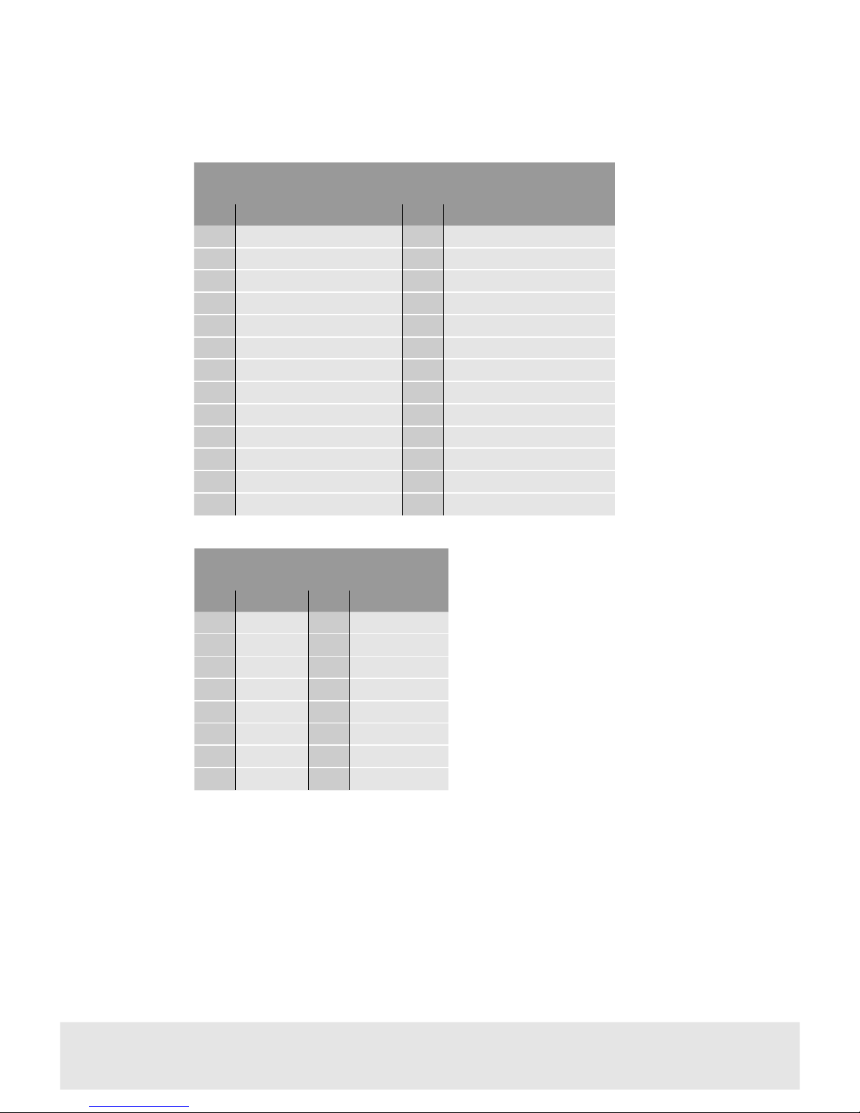
The following 5V ‘auxiliary’ signals are for Pro-Bel use only; CBL(block start), Channel
Status, User Data and Sample Rate Clock. These pins should not be grounded or
terminated.
44115
Technical Manual
Analogue audio out
PinFunctionPinFunction
1
AUDL1+
9
AUDL1-
2
GND
10
AUDR1+
3
AUDR1-
11
GND
4
N/C
12
N/C
5
GND
13
AUDL2+
6
AUDL2-
14
GND
7
AUDR2+
15
AUDR2-
8
GND
AES in + AUX out
PinFunctionPinFunction
1
N/C
14
N/C
2
Sample Rate Clock, Ch 1
15
Sample Rate Clock, Ch 2
3
GND
16
GND
4
N/C
17
N/C
5
CBL, Ch1
18
CBL, Ch 2
6
AES IP2-
19
AES IP 1 -
7
AES IP2+
20
AES IP1+
8
GND
21
N/C
9
N/C
22
Channel Status, Ch 2
10
Channel Status, Ch 1
23
GND
11
GND
24
N/C
12
N/C
25
User Data, Ch 2
13
User Data, Ch 1
Page 6
3
Configuration
3.1Configuring AES inputs
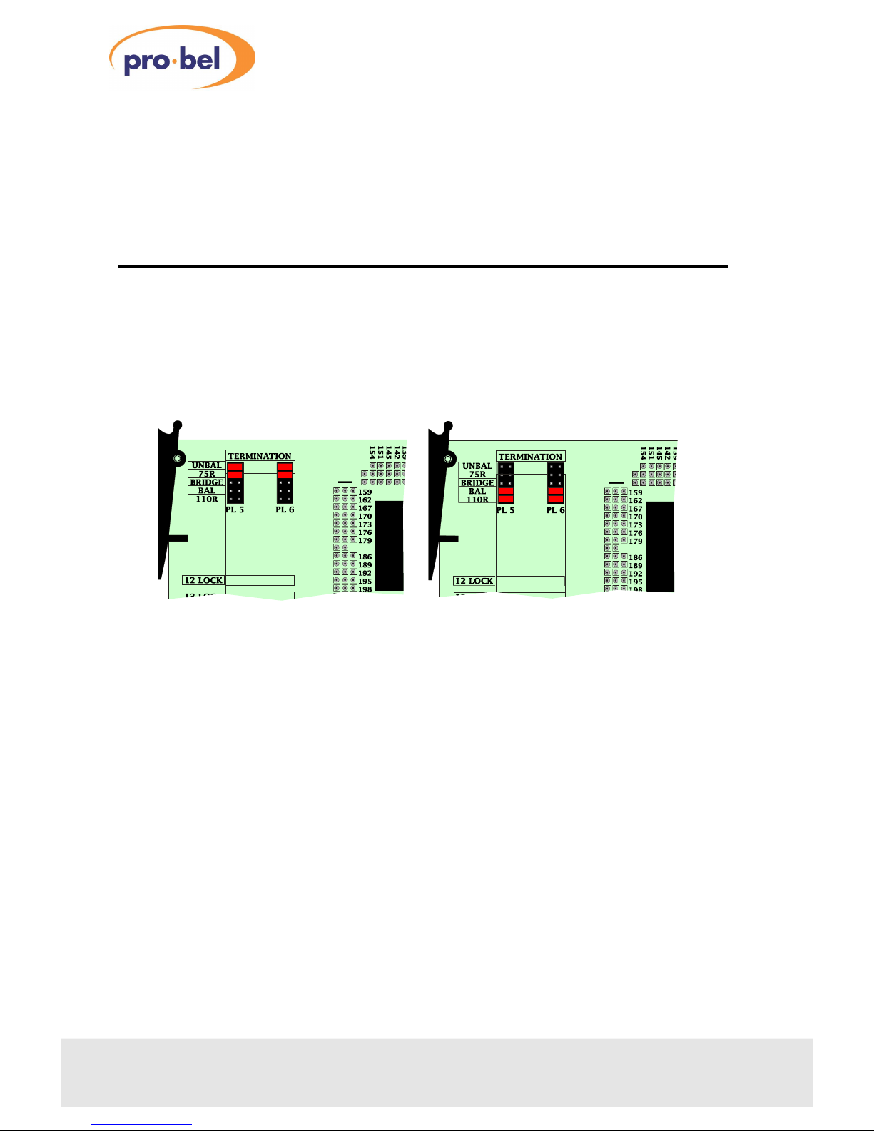
Jumper blocks PL5 and PL6 are provided to set AES input termination values and
select balanced or unbalanced operation.
DAC inputs can be balanced or unbalanced and of different termination values .
However, these parameters will be determined by the system installation and to
some extent the choice of back connector.
6
Issue 1
Audio Digital to Analogue Converter
Example termination for
unbalanced 75 W AES inputs
Example termination for
balanced 110 W AES inputs
Page 7
3.2Setting analogue output levels
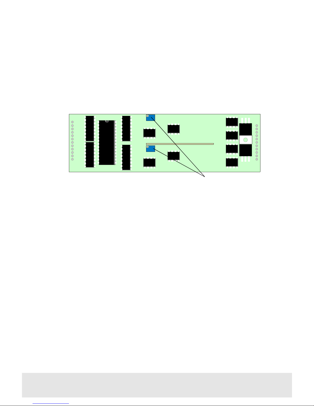
The analogue output levels of each 5635 DAC sub-module can be adjusted with RV1
for the right channel and RV2 for the left channel. The adjustment range is +15dBu
to +24dBu for Full Scale Digital (maximum digital value). Standard factory setup is
+18dBu=0dB, FSD for Europe and +24dBu=0dB, FSD for the US. See ‘Ordering
Information’ for the appropriate order codes for the two setup options.
44117
Technical Manual
LEFT
RV2
RIGHT
RV1
5635
P
Converter gain
Page 8

4 Trouble shooting
There is no output signal
•
ensure that the green power LED on the front of the card is lit
If not:
•
check the resettable fuses protecting the card - do this by removing the power
to the card for about 30 seconds then restore the power
• check the PSU indicators to confirm that there is power to the frame
• check that the inputs are connected to the rear panel and valid signals are
present
• check that the red Invalid LED is not lit for either sub-module
•
check that the red Loss of I/P is not lit for either sub-module
Notes:
The card edge green power LED will only illuminate if all voltage rails regulated on
the module are present.
The Invalid LED will light if the Validity bit in the input bit-stream has been set to 1,
to indicate that the associated sample is not suitable for conversion. This could
occur if other than a linear PCM digital signal, such as Dolby AC3, were ever input
to the card.
The output signal is corrupted
•
check the quality of the input signal
• check that the appropriate terminations have been set
•
check that a green sample rate LED is lit and is appropriate for each sub-module
input
The output signal has pops and clicks sometimes
• check for a valid common reference for all digital audio source or processing
equipment in the system
Note: It is recommended to employ a common station video reference or a common
AES11 reference for all digital audio equipment if accurate phasing to station signals
is required throughout a facility.
8
Issue 1
Audio Digital to Analogue Converter
Page 9
Status indicators
44119
Technical Manual
Status indicators
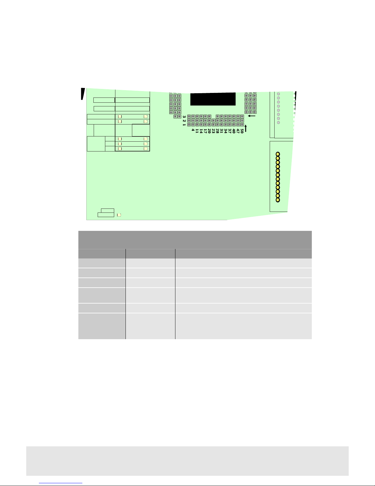
LED label4411 functionMeaning when lit
12 LOCK
Not fitted
13 LOCK
Not fitted
LOSS OF I/P
Loss of inputLights red for loss of input on either sub-module
INVALID
Invalid input
Lights red to Indicate an invalid AES input on either
sub-module
POWER
Power OKLights green if all voltage rails present
SAMPLE
RATE
48K
44K
32K
48kHz sample rate detected
44.1kHz sample rate detected
32kHz sample rate detected
4411 status indicator assignments
POLL
POWER
12 LOCK
13 LOCK
LOSS OF I/P
INVALID
48K
44K
32K
SAMPLE
RATE
CH12
70
67
64
59
56
53
189
192
195
198
203
206
Page 10

5 COSMOS Status Monitoring
If the frame is equipped with a COSMOS controller card, the following parameters
will be reported back to the COSMOS status monitoring system.
• module present
• sample rate detected, DAC one and DAC two
•
loss of input, DAC one and DAC two
• invalid input, DAC one and DAC two
•
power OK
In addition, the module is programmed with the following information, which can be
read by the status monitoring controller:
• Module type
• Module bar code
•
Module issue no
For further details of the Pro-Bel status monitoring system please refer to the
COSMOS status monitoring manual.
10
Issue 1
Audio Digital to Analogue Converter
Page 11

441111
Technical Manual
Page 12

6 Specification
Inputs (per sub-module)
Number and type:1, AES3-1992 balanced or AES3-id
unbalanced
Impedance:selectable 110W, 75W or high impedance
Outputs (per sub-module)
Number and type:2, analogue audio, electronically balanced
Level at 0dB, FSD:+15dBu to +24dBu
Auxiliary 5V logic signals
(per sub-module):Sample rate clock
Channel status
User data
Block start (CBL)
Performance
Sample rate:32kHz to 54kHz continuous automatic
adjustment
Frequency response: ± 0.05dB 50Hz to 15kHz,
± 0.2dB 40Hz to 20kHz
THD+N:<0.007% at 1kHz and -1dB FSD
<0.1%, 50Hz to 15kHz, -28dB FSD
Noise (idle channel):-96dB quasi-peak weighted
(-78dBu for 0dB FSD=+18dBu)
Dynamic range:107dB (measured)
Indicators
Power on:Green LED
Loss of input 1&2:Red LED
Invalid input 1&2:Red LED
Sample rate:yellow LEDs, 48K, 44K and 32K
12
Issue 1
Audio Digital to Analogue Converter
Page 13

Temperature range
Operating:0° to +40°C
Storage:-10°C to +70°C
441113
Technical Manual
Page 14

7 Ordering information
ICO-4411-3BHSAudio DAC with 30mm rear panel, balanced AES3 input, peak
level +24dBu, single stereo converter
ICO-4411-3BHDAudio DAC with 30mm rear panel, balanced AES3 inputs,
peak level +24dBu, dual stereo converter
ICO-4411-3BLSAudio DAC with 30mm rear panel, balanced AES3 input, peak
level +18dBu, single stereo converter
ICO-4411-3BLDAudio DAC with 30mm rear panel, balanced AES3 inputs,
peak level +18dBu, dual stereo converter
ICO-4411-3UHSAudio DAC with 30mm rear panel, unbalanced AES3 input,
peak level +24dBu, single stereo converter
ICO-4411-3UHDAudio DAC with 30mm rear panel, unbalanced AES3 inputs,
peak level +24dBu, dual stereo converter
ICO-4411-3ULSAudio DAC with 30mm rear panel, unbalanced AES3 input,
peak level +18dBu, single stereo converter
ICO-4411-3ULDAudio DAC with 30mm rear panel, unbalanced AES3 inputs,
peak level +18dBu, dual stereo converter
14
Issue 1
Audio Digital to Analogue Converter
 Loading...