

Page 1

Contents
1Introduction
2
2Installation 4
2.1Signal I/O and control pinout
5
2.2Crosspoint control 7
3Configuration 10
3.1Input set-up
12
3.2Configuring an 8x1 switcher 13
3.3Source expansion 14
3.4Level expansion 17
3.5Building a 64 input switcher
19
3.6Using the 4408 with the 4405 re-framer 23
4Trouble shooting 24
5COSMOS status monitoring 26
6Specification
28
7Ordering Information
30
Technical Manual
1
4408Digital Audio 8x1 Switch
Page 2

1 Introduction
The 4408 is an eight input, one output AES/EBU digital audio switcher with a choice
of rear connector to support balanced or unbalanced I/O. It is designed to fit in the
1050 3U and 1051 1U Pro-Bel ICON modular product rackframes.
The switcher provides a solution for small ancillary or monitoring matrices with the
benefit of simple button per crosspoint control.
The architecture of the modules allow crosspoint outputs to be bussed together to
allow switchers above eight inputs to be built. In addition the AES/EBU digital audio
switcher may be configured with other modules in the Pro-Bel range to form married
multi-level matrices.
An onboard rechargeable battery provides retention of crosspoint settings after
power loss.
Characteristics of the 4408 module are:
•
I/O selectable for balanced or unbalanced operation
• easy expansion up to 64 inputs
•
flexible control, with button per crosspoint or binary addressing
•
synchronised switching using an external video field pulse
•
can be used with the 4405 re-framer for glitch-free switching
• standalone and master slave configuration
•
crosspoint memory via battery backup
•
card edge yellow LED crosspoint tally display
• compatible with Pro-Bel COSMOS status monitoring
2
Issue 3
4408
Page 3
Technical Manual
3
4408Digital Audio 8x1 Switch
CONTROL
INPUTS AND
LAMP SUPPLY
DC POWER
AND
STATUS DATA
AUD / CNTL
EXP IN
AUD / CNTL
EXP OUT
ADDRESS
EXP OUT
BAL/UNBAL
DIGITAL
AUDIO
INPUTS
BAL/UNBAL
DIGITAL
AUDIO
OUTPUT
ADDRESS
EXP IN
CONTROL
LOGIC
POWER
REG
EXPANSION
CONFIG
BATT
OUTPUT
SWITCH
STATUS
MON
8x1
SWITCH
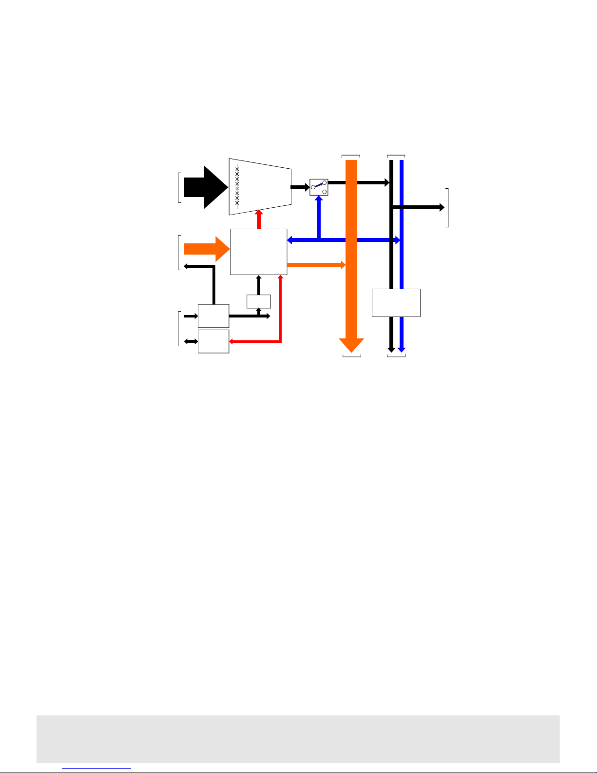
The 4408 audio switch
Page 4
2 Installation
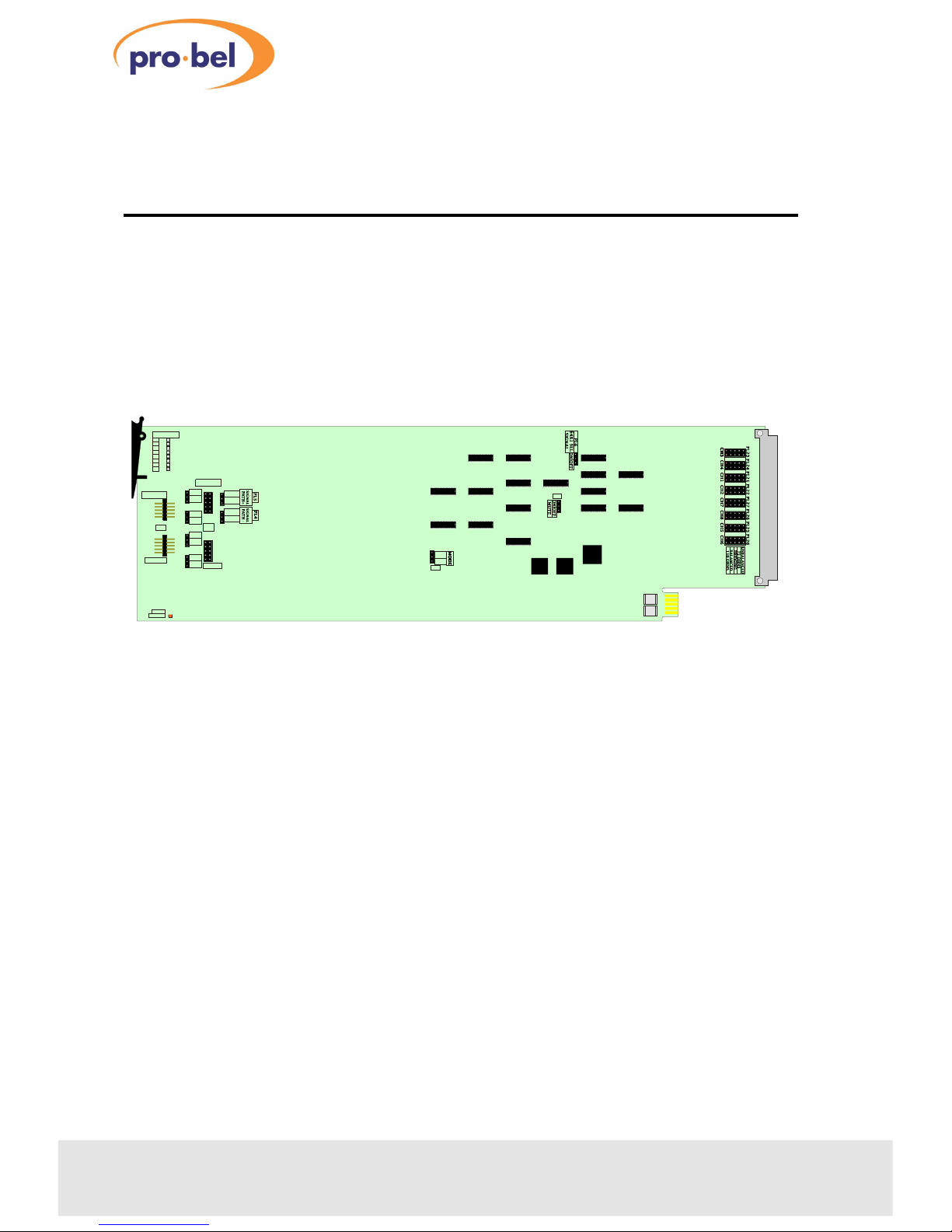
The 8x1 digital audio switch consists of an 4408 ICON module which fits in either a
1U 1051 or a 3U 1050 ICON Pro-Bel modular rackframe. It is available with two rear
connectors, the 20mm K4408.2B for balanced signals and the 30mm K4408.3U for
unbalanced signals.
For module and rear connector installation please refer to the appropriate ICON
rackframe section of the manual.
4
Issue 3
4408
RSF1
RSF2
4408
POLL
POWER
BINARY
PL9
OFF
PL10
ON
PL12
PL13
PL7
OFF
ON
PL8
CHAN SEL
1
2
3
4
5
6
7
8
PL14
OFF
ON
OFF
ON
PL11
CONTROL
CONTROL
BINARY
I/P
1
1
1
1
O/P
MAKE
BRK
MAKE
BRK
BIN
BUT
BIN
BUT
PL3
PL2
P
The 4408 digital audio 8x1 switch
Page 5
2.1Signal I/O and control pinout
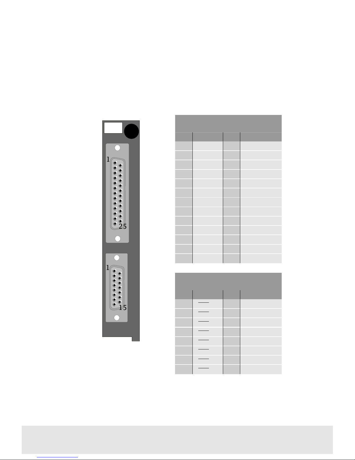
The K4408.2B rear connector has one 25 way ‘D’ female socket for balanced signal
I/O and one 15 way ‘D’ type socket for control.
Technical Manual 5
4408Digital Audio 8x1 Switch
Signal I/O (K4408.2B)
PinFunctionPinFunction
1
IP3-
14
IP7-
2
IP3-+
15
IP7+
3
GND
16
GND
4
IP4-
17
IP8-
5
IP4+
18
IP8+
6
OP-
19
N/C
7
OP+
20
N/C
8
GND
21
IP5-
9
IP1-
22
IP5+
10
IP1+
23
GND
11
GND
24
IP6-
12
IP2-
25
IP6+
13
IP2+
K4408
.2B
S
I
G
N
A
L
I
/
O
C
O
N
T
R
O
L
Control Pin outs
PinFunctionPinFunction
1
SEL 1
9
A0EXT
2
SEL 2
10
A1EXT
3
SEL 3
11
A2EXT
4
SEL 4
12
A3EXT/64x1
5
SEL 5
13
LAMPSUP
6
SEL 6
14
OV
7
SEL 7
15
SCREEN
8
SEL 8
Page 6
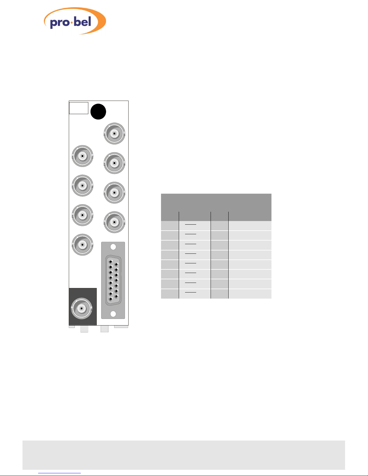
The K4408.3U uses the same 15 way ‘D’ connector for control but BNC connectors
are used for the unbalanced signal I/O. Where possible, the ICON colour scheme
reserves a grey background for outputs and a white background for inputs.
6
Issue 3
4408
K4408
.3U
AES OUT
7
5
3
1
8
6
4
2
CONTROL
AES IN
Control Pin outs
PinFunctionPinFunction
1
SEL 1
9
A0EXT
2
SEL 2
10
A1EXT
3
SEL 3
11
A2EXT
4
SEL 4
12
A3EXT/64x1
5
SEL 5
13
LAMPSUP
6
SEL 6
14
OV
7
SEL 7
15
SCREEN
8
SEL 8
Page 7
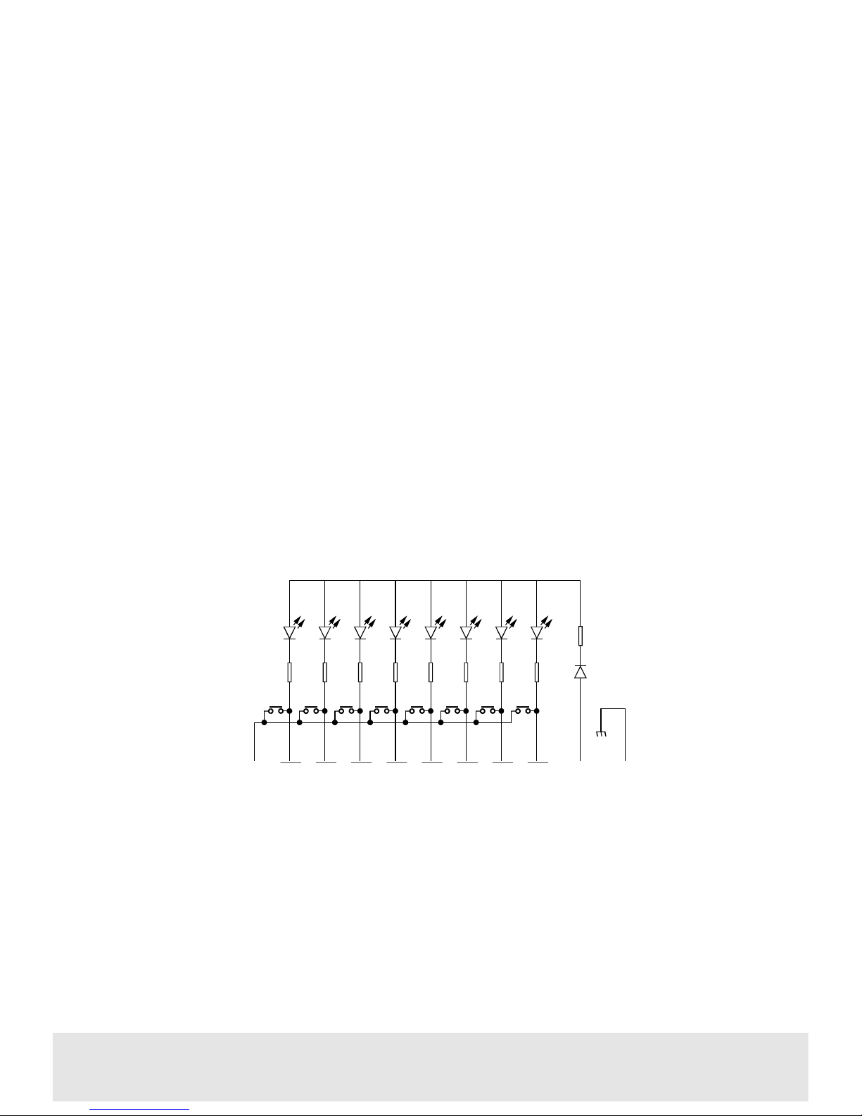
2.2Crosspoint control
Connecting button panels
Crosspoints may be selected by connecting a button panel (eg. Pro-Bel’s 8 button
6200 or 16 button 6202) to the control socket on the rear panel and setting PL3 to
‘BUTTON’.
The analogue audio switcher card has priority switching built in. If two keys are
pressed simultaneously, the higher numbered one will be selected. This feature
allows signal ‘line up’ to be performed quickly. To achieve this, one key must be
held down and a higher numbered key pushed and released. Each time the higher
numbered key is pushed and released that source will be selected, as long as the
button is held down. Once the button is released, the previous source is selected
again.
Two 8x1 modules may be independently controlled from a 16 button panel, such as
the Pro-Bel 6202. This particular panel has two separate connectors to plug into the
control socket on each module, simplifying the installation. If the internal
expansion cables are fitted (see Source expansion), priority switching can be
performed across several modules. The highest priority module will always be the
left most, viewed from the front of the cards.
Using binary control
To use binary control instead of a button panel, PL3 must be set to ‘BIN’. Crosspoints
may be then selected by binary addressing using 12V CMOS levels.
Technical Manual 7
4408Digital Audio 8x1 Switch
SEL 1 SEL 2 SEL 3 SEL 4 SEL 5 SEL 6 SEL 7 SEL 8OV
LAMPSUP GND
Example 8 way button panel wiring
Page 8
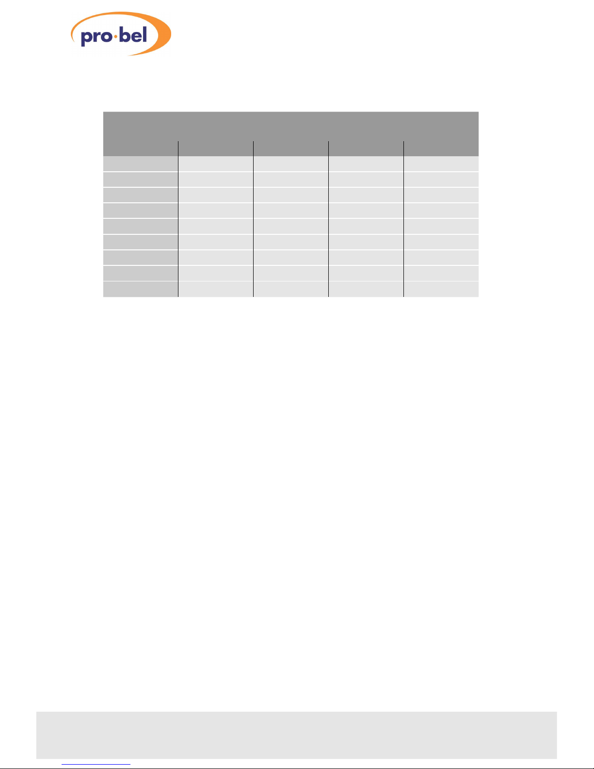
* Crosspoint output is tri-stated - used for system expansion.
LOGIC 1 = +12V, LOGIC 0 = 0V
For externally supplied binary signals wiring must be made to the rear panel. To
select an input the correct binary address is needed and A3EXT must be logic 0. For
source expansion, all other modules whose inputs are not selected, A3EXT must be
at logic 1.
Binary control signals can be generated by one 8x1 module and fed to another, to
create a master slave configuration. To achieve this, the lower expansion cable on
the front of the cards must be fitted, and all slave modules set to binary mode. The
master module can be set to button mode and conveniently driven from a button
panel.
Note: The A3 EXT line (input) becomes the 64x1 select line (output) for systems
expanded to 64x1 with PL6 in the ON position.
8
Issue 3
4408
Binary addressing
I/PA2EXTA1EXTA0EXTA3EXT
1
0000
2
0010
3
0100
4
0110
5
1000
6
1010
7
1100
8
1110
*
XXX1
Page 9

Technical Manual 9
4408Digital Audio 8x1 Switch
Page 10
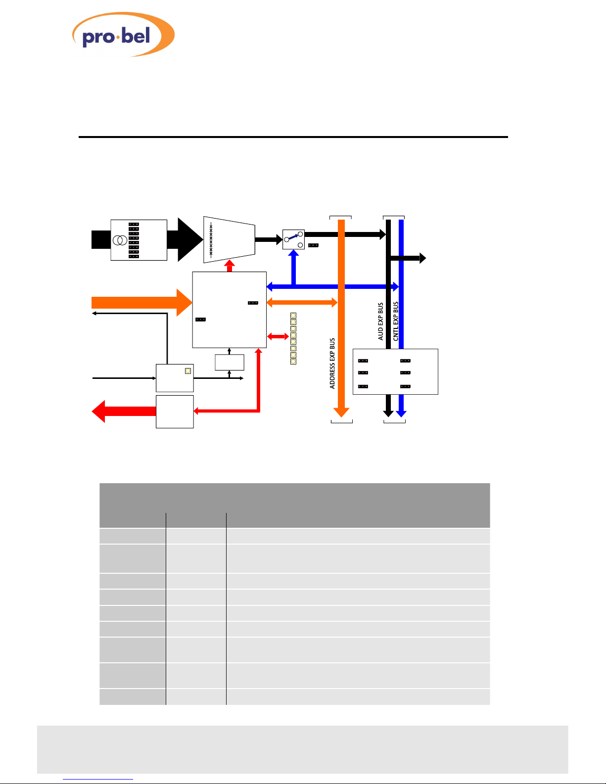
3 Configuration
The module is easy to configure and build into expanded systems using expansion
cables and jumpers.
10
Issue 3
4408
4408 8x1 switch schematic view
PL7
PL8PL10
PL4
PATH +
PL5
DIS OUT
PL11
CLOCK I/O
PL12
FLD TRIG
PL13
BATT SUP
PL14
8x1
8 BALANCED OR UNBALANCED
DIGITAL AUDIO INPUTS
BAL/UNBAL
DIGITAL AUDIO
OUTPUT
PL9
EXPANSION
ENABLE
JUMPERS
STATUS DATA
STATUS
MON
CONTROL PANEL AND
BINARY SELECT LINES
LAMP SUPPLY
LOW VOLTAGE
DC SUPPLY
MODE
BUTTON/BIN
PL3
PL6
PL2
64X1 SELECT
MUTE
CHANNEL SELECT LEDS
CH 1
CH 2
CH 3
CH 4
CH 5
CH 6
CH 7
CH 8
POWER LED
CONTROL
LOGIC
POWER
REG
BATT
PATH -
PL23 - PL26
INPUT
SET-UP
8x1
OUTPUT
SWITCH
Configuration jumpers
JumperConditionFunction
PL2
MUTEUsed with the 4405 re-framer
PL3
BUTTON
BIN
Simple button per crosspoint control
Binary control, used in expanded systems and computer control
PL4&PL5
OFF or ONAudio expansion bus , used when expanding sources
PL6
OFF or ON64x1 select, modifies binary addressing when expanding above 32x1
PL11
OFF or ONDIS OUT, used to disable downstream cards when expanding sources
PL12
OFF or ONCLOCK I/O, output clock for downstream cards when expanding sources
PL13
OFF or ON
FIELD TRIGGER, used to distribute to downstream cards for synchronous
switching
PL14
OFF or ON
Battery supply, used to distribute 3.6V crosspoint retention power to
other boards in a system
PL23-PL26
Five positionUsed to select set-up for each input - see separate chart
Page 11
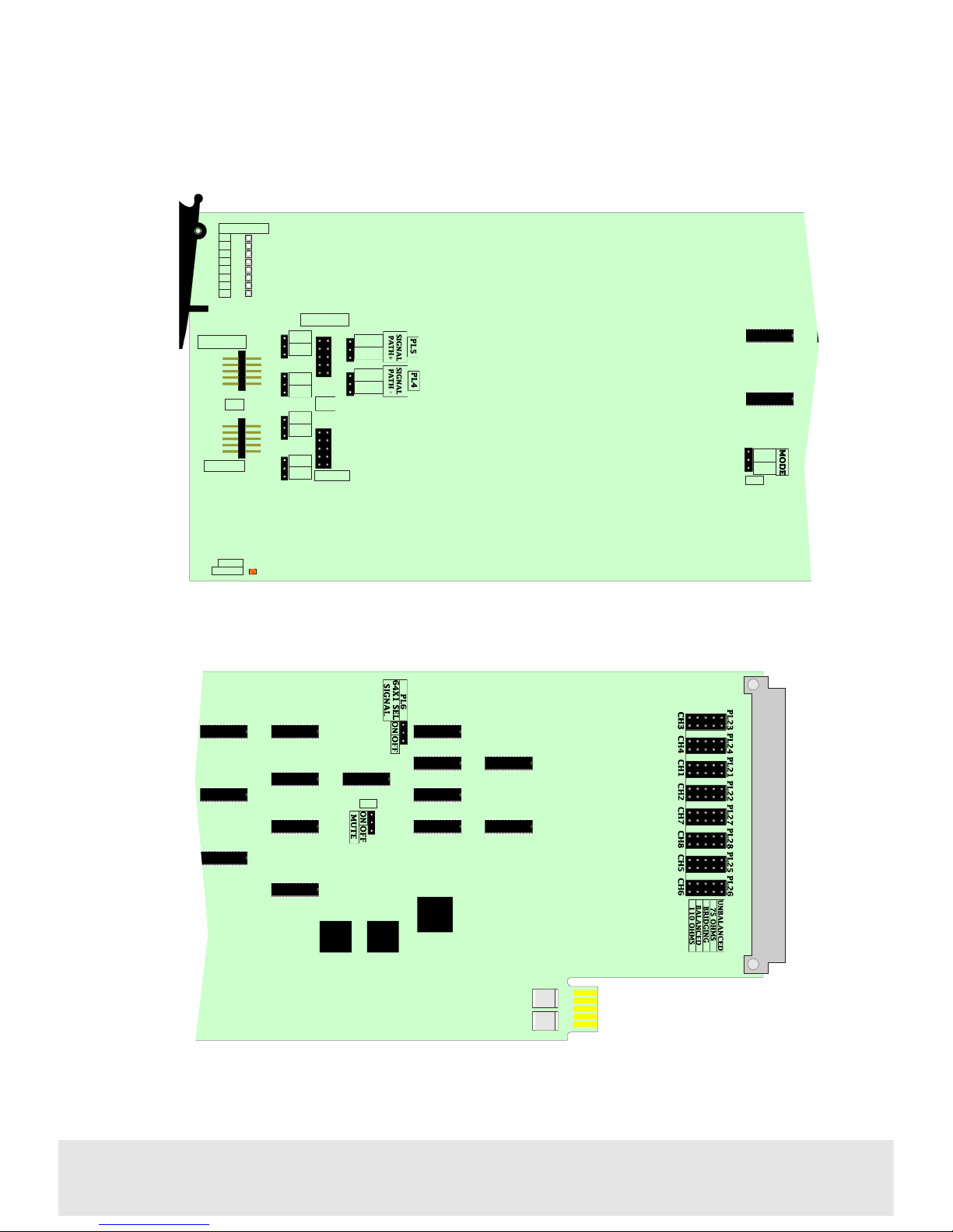
Technical Manual 11
4408Digital Audio 8x1 Switch
Jumper locations at front of card
RSF1
RSF2
PL2
Jumper locations near edge connector
4408
POLL
POWER
BINARY
PL9
OFF
PL10
ON
PL12
PL13
PL7
OFF
ON
PL8
CHAN SEL
1
2
3
4
5
6
7
8
PL14
OFF
ON
OFF
ON
PL11
CONTROL
CONTROL
BINARY
I/P
1
1
1
1
O/P
MAKE
BRK
MAKE
BRK
BIN
BUT
BIN
BUT
PL3
P
Page 12
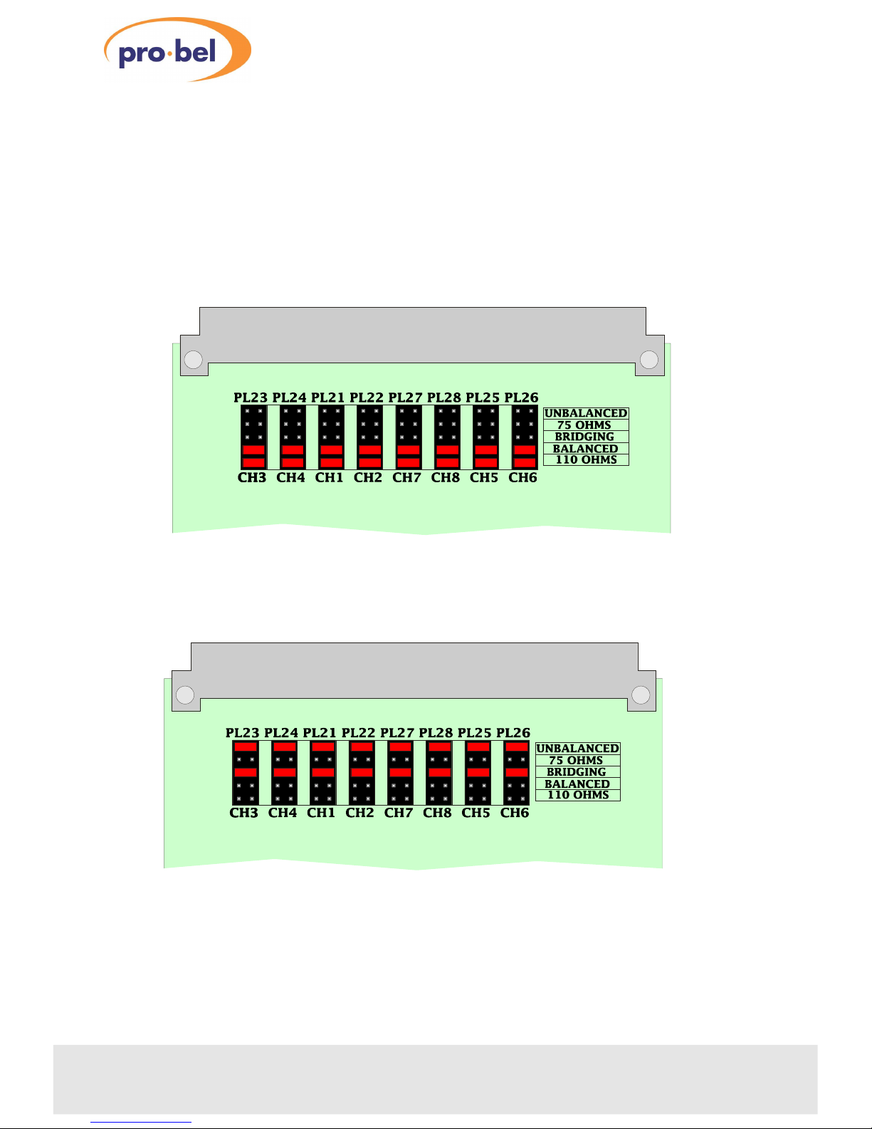
3.1Input set-up
Jumpers are provided so that the eight inputs may be configured for different
termination values and set for balanced or unbalanced operation.
12
Issue 3
4408
Example: all inputs set to balanced, 110 Ω
Example: all inputs set to Hi-Z, unbalanced
Page 13
3.2Configuring an 8x1 switcher
The simplest configuration is a single 8x1 module without expansion.
Control of the switcher may be from either a simple control panel or in binary form
from a more complex control system such as a computer. PL3 is used to establish the
method of crosspoint control. All other jumpers positions can be ignored since they
only affect expansion.
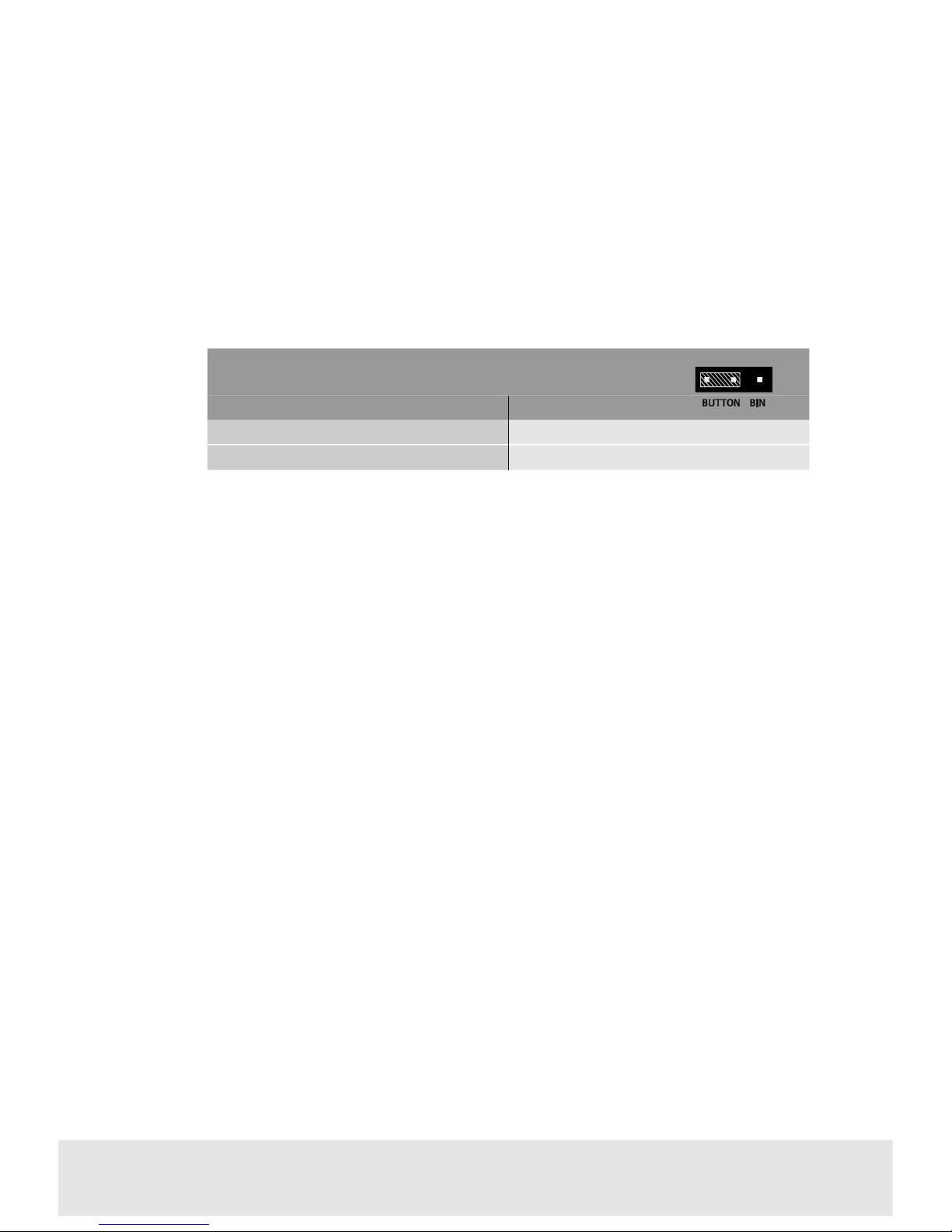
Configuration changes are accomplished by pulling the jumper (the shaded area
above) from its current position on the header pins and moving it to the alternate
position desired. The jumper must make electrical contact with at least two pins.
Technical Manual
13
4408Digital Audio 8x1 Switch
PL3 Crosspoint control mode
PositionFunction
BUTTON
Crosspoint selection using a button panel
BIN
Crosspoint selection using binary control
Page 14
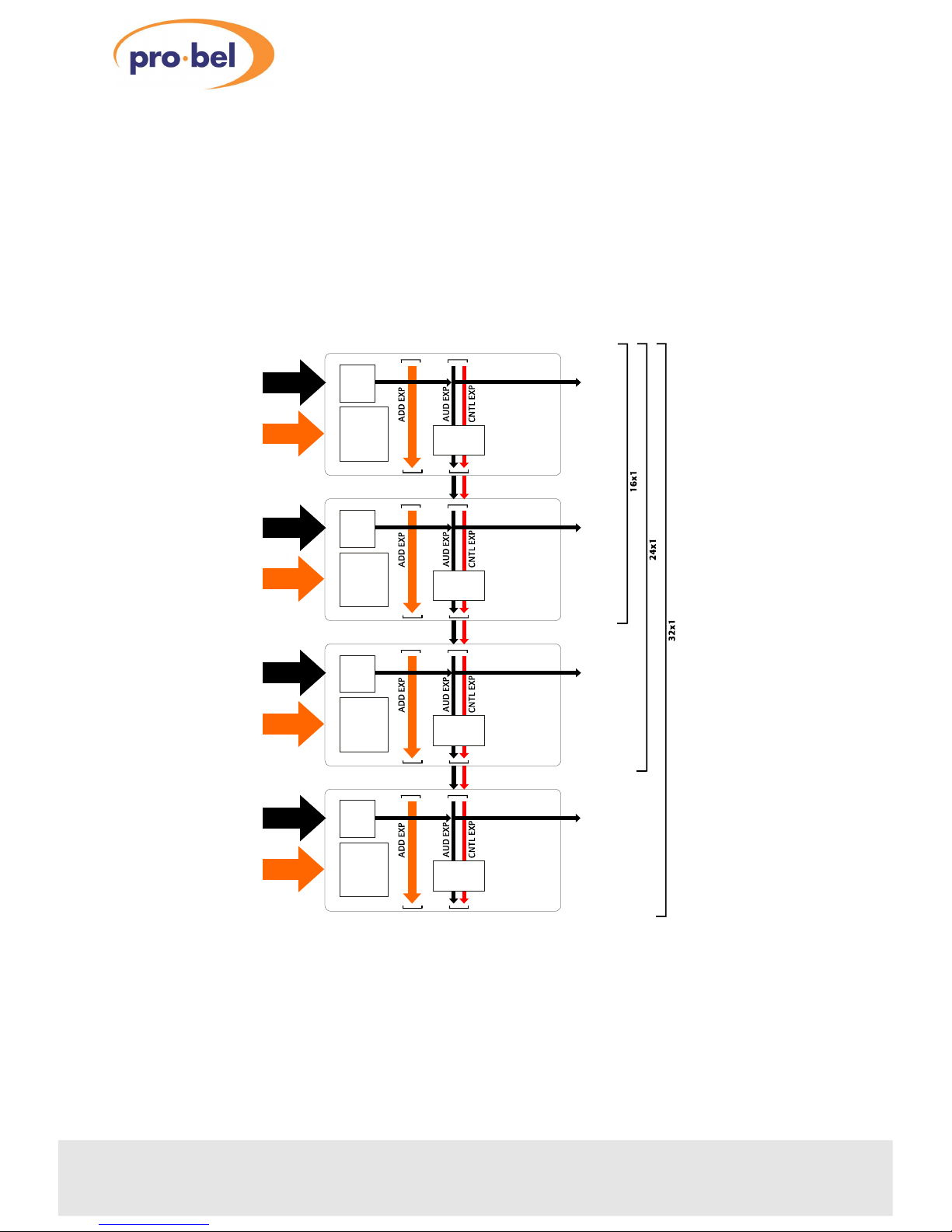
3.3Source expansion
Several analogue audio switcher cards can be linked to make larger switchers up to
64x1. For switchers up to 32x1, only 4 modules are needed. Larger switchers need
an extra 4408 as a combiner module. Expansion employs the front of card
connectors together with the ribbon cables supplied with the card.
14
Issue 3
4408
CONTROL
INPUTS
1 TO 8
AUDIO INPUTS
1 TO 8
AUDIO
OUTPUT
EXPANSION
CONFIG
PL9
8 X 1
PL7
PL10PL8
PL4,5: ON
PL11,12: ON
PL13,14: OFF
CONTROL
INPUTS
9 TO 16
AUDIO INPUTS
9 TO 16
AUDIO
OUTPUT
EXPANSION
CONFIG
PL9
8 X 1
PL7
PL10PL8
CONTROL
INPUTS
17 TO 24
AUDIO INPUTS
17 TO 24
AUDIO
OUTPUT
EXPANSION
CONFIG
PL9
8 X 1
PL7
PL10PL8
CONTROL
INPUTS
25 TO 32
AUDIO INPUTS
25 TO 32
AUDIO
OUTPUT
EXPANSION
CONFIG
PL9
8 X 1
PL7
PL10PL8
PL6 64x1
OFF
PL3 MODE
BUTTON
PL6 64x1
OFF
PL3 MODE
BUTTON
PL6 64x1
OFF
PL3 MODE
BUTTON
PL6 64x1
OFF
PL3 MODE
BUTTON
PL4,5: ON
PL11,12: ON
PL13,14: OFF
PL4,5: ON
PL11,12: ON
PL13,14: OFF
Expanding to 16, 24 and 32 x 1
Page 15
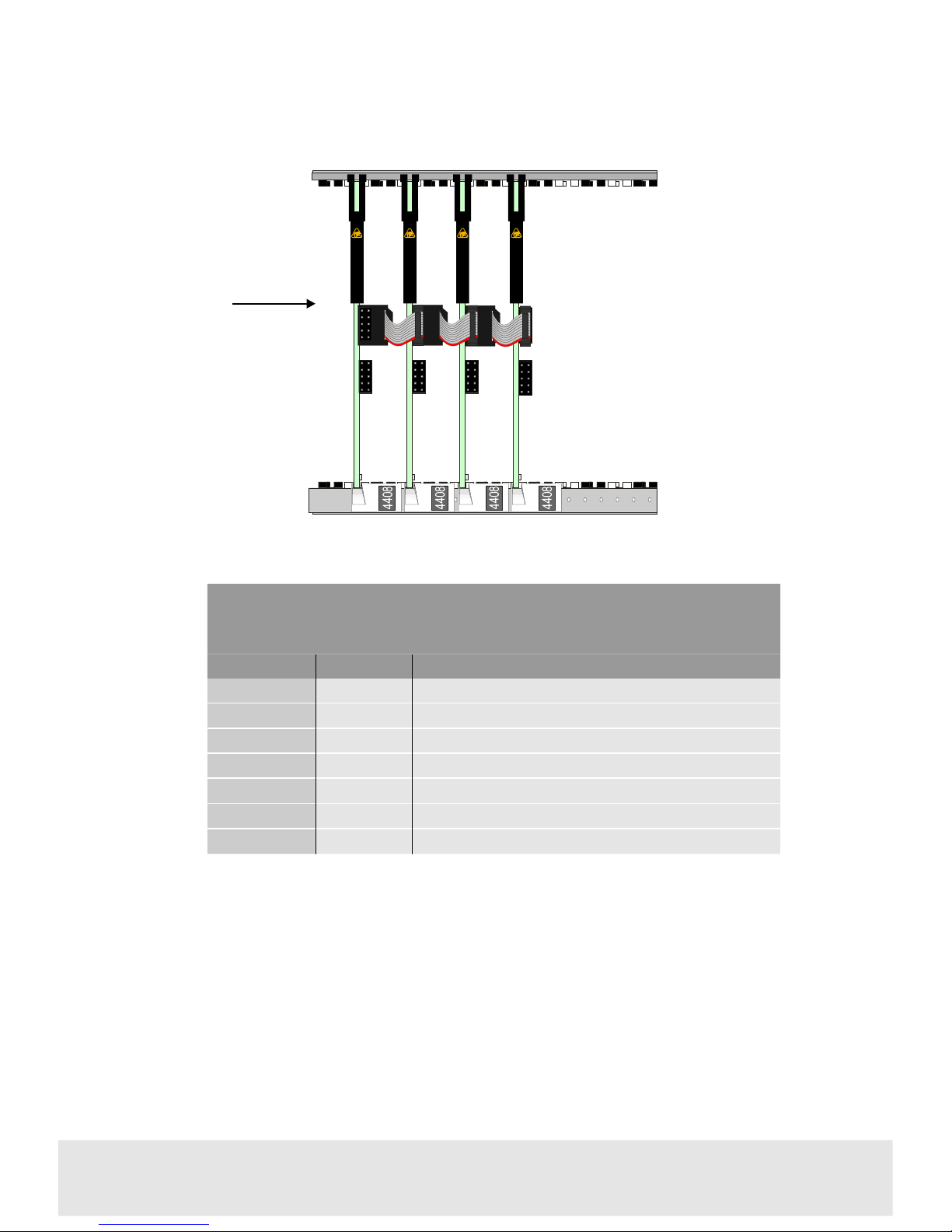
Synchronous switching
If synchronous switching using a video vertical timing pulse is required, an extra
module such as a 3408 digital video 8x1 switch or a 3438 analogue video 8x1 switch
with a 2315 sync separator is required.
In addition, a ribbon cable from PL7 on the 3408/3438, should be connected to PL 7
on the upsteam (left most) 4408 in a system. The 3408/3438 should be jumpered to
only provide the vertical timing pulse on the control bus.
Technical Manual 15
4408Digital Audio 8x1 Switch
PL7
PL8
BEHIND PL7
PL9
PL7
PL8
BEHIND PL7
PL9
PL7
PL8
BEHIND PL7
PL9
PL7
PL8
BEHIND PL7
PL9
4
4
0
8
4
4
0
8
4
4
0
8
4
4
0
8
VID/CNTL EXPANSION
SIGNAL FLOW
Expansion cabling for an asynchronous 32x1 switcher
Source expansion jumper settings with button control and
asynchronous switching
JumperSettingFunction
PL3
BUTTONControl mode
PL4 & PL5
ONDigital audio signal expansion O/P
PL6
OFF64x1 select signal
PL11
ONDIS OUT priority switching signal
PL12
ONOutput clock
PL 13
OFFSynchronous switching mode
PL14
OFFCommon battery supply line
Page 16
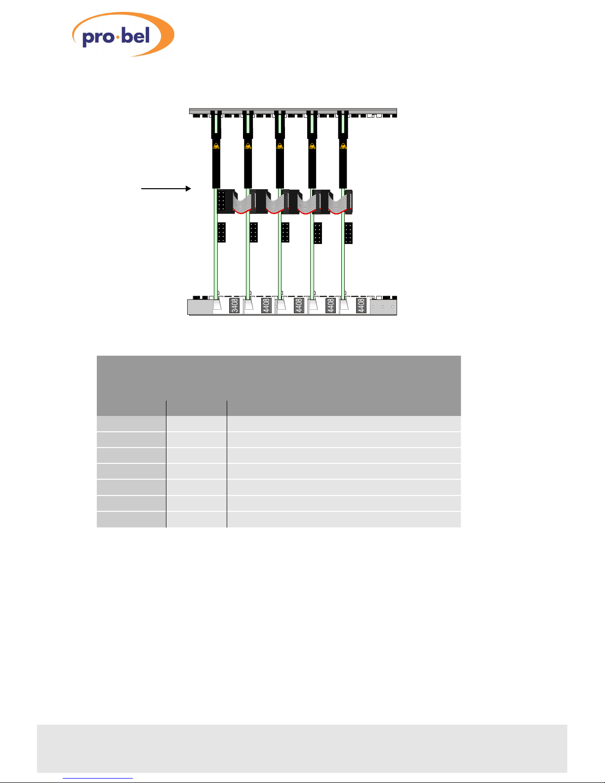
The following rules apply to source expansion from 16x1 to 32x1:
•
only audio/control expansion bus used
•
expansion jumpers not needed on last card in chain
• buffered outputs available from all cards
• Synchronous switching between audio sources is only possible if all sources are
synchronised to one reference.
16
Issue 3
4408
PL7
PL8
BEHIND PL7
PL9
PL7
PL8
BEHIND PL7
PL9
PL7
PL8
BEHIND PL7
PL9
3
4
0
8
4
4
0
8
4
4
0
8
4
4
0
8
VID/CNTL EXPANSION
VERT SYNC
PL7
PL8
BEHIND PL7
PL9
4
4
0
8
Source expansion jumper settings with button control and
synchronous switching
JumperSettingFunction
PL3
BUTTONControl mode
PL4 & PL5
ONDigital audio signal expansion O/P
PL6
OFF64x1 select signal
PL11
ONDIS OUT priority switching signal
PL12
ONOutput clock
PL 13
ONSynchronous switching mode
PL14
OFFCommon battery supply line
Expansion cabling for synchronous 32x1 switcher
Page 17
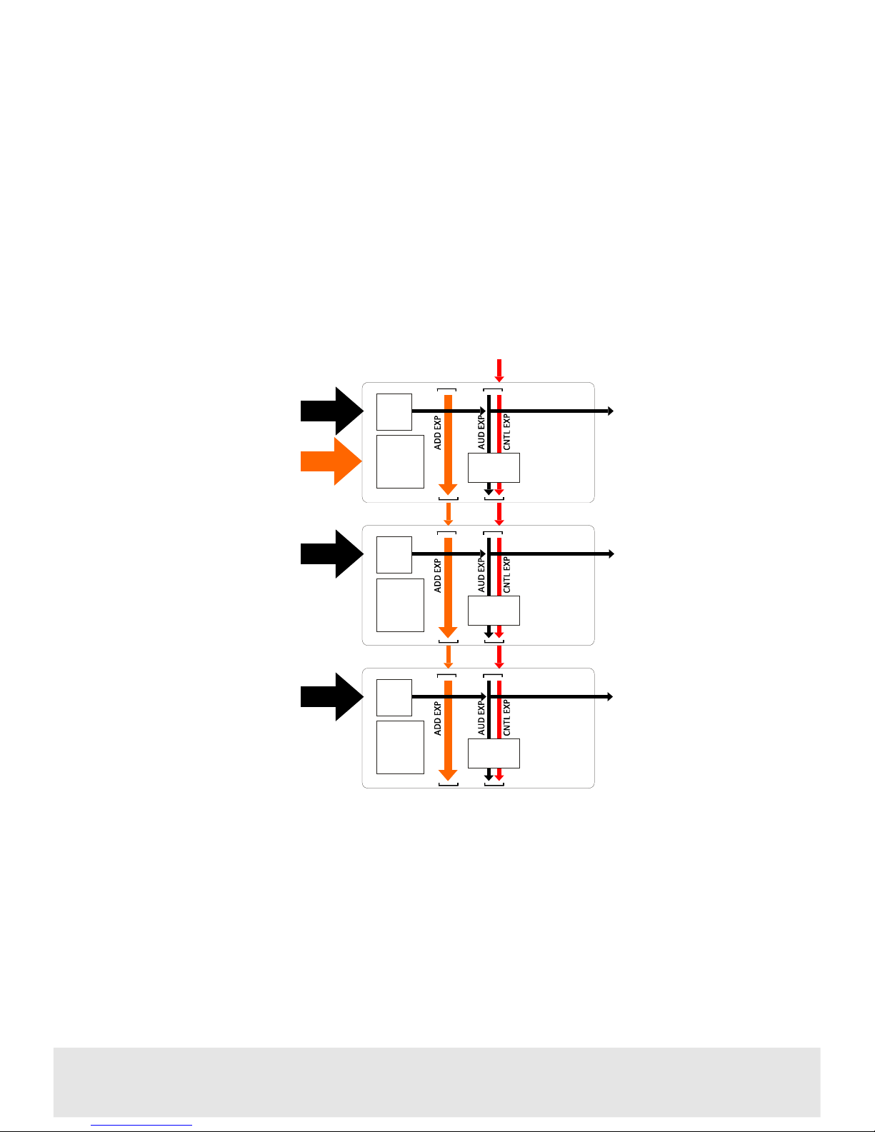
3.4Level expansion
It may be useful in some applications for one card to control the input selection of
other cards to create a multi-level switcher. This mode is called master/slave and
utilises the binary control interconnections.
The master card can be driven from a button panel and all other cards by binary
addressing using only the lower expansion connectors PL8-PL9 on the front of the
card.
In this example of a synchronous three level audio switcher, both address and
control/audio expansion bus connectors are used. It may be desirable to distribute a
vertical interval trigger signal from an external card to ensure switching during the
correct line of a reference video field. This is why the aud/cntl ribbon is used.
However, the AUD expansion jumpers PL4 and PL5 must be off on all cards.
Technical Manual 17
4408Digital Audio 8x1 Switch
CONTROL
INPUTS
1 TO 8
AUDIO LEVEL 1
INPUTS 1 TO 8
AUDIO LEVEL 1
OUTPUT
VERTICAL PULSE
FROM VIDEO MODULE
EXPANSION
CONFIG
PL8
8 X 1
PL6
PL9PL7
AUDIO LEVEL 2
INPUTS 1 TO 8
AUDIO LEVEL 2
OUTPUT
EXPANSION
CONFIG
PL8
8 X 1
PL6
PL9PL7
AUDIO LEVEL 3
INPUTS 1 TO 8
AUDIO LEVEL 3
OUTPUT
EXPANSION
CONFIG
PL8
8 X 1
PL6
PL9PL7
PL6 64x1
OFF
PL3 MODE
BUTTON
PL6 64x1
OFF
PL3 MODE
BIN
PL6 64x1
OFF
PL3 MODE
BIN
PL4,5: OFF
PL11,14: OFF
PL12,13: ON
ONLY CONTROL
MODE JUMPER,
PL3 MUST BE
SET ON
LAST CARD
PL4,5: OFF
PL11,14: OFF
PL12,13: ON
Example of level expansion:
synchronous three level audio 8x1 switcher
Page 18
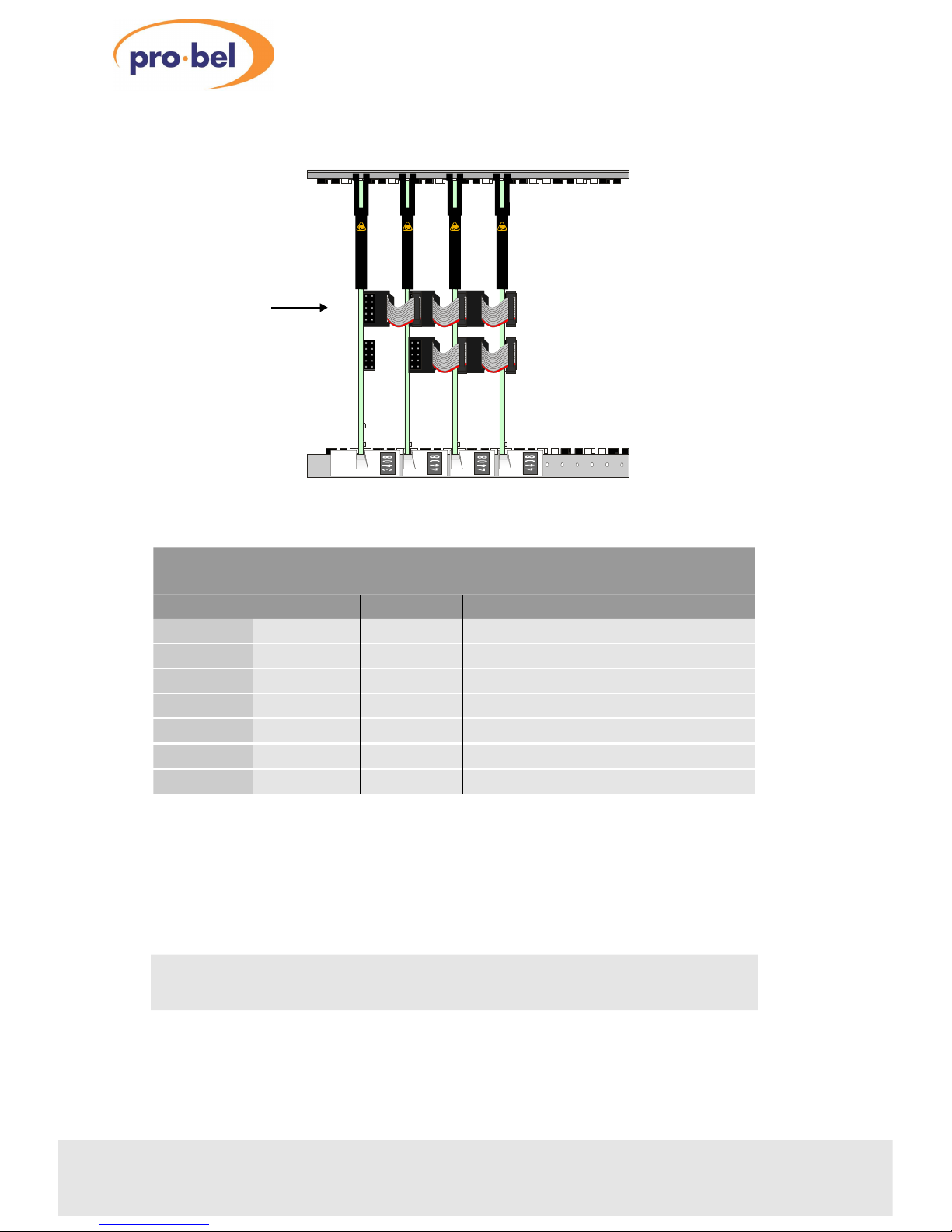
The following rules apply to synchronous level expansion
• Address and control expansion buses used
•
Expansion jumpers not needed on last card in chain
•
Synchronous switching between audio sources is only possible if all sources are
already synchronised to one reference
18
Issue 3
4408
Example of three level expansion wiring
PL7
PL8
BEHIND PL7
PL10
BEHIND PL9
PL9
PL7
PL8
BEHIND PL7
PL10
BEHIND PL9
PL9
PL7
PL8
BEHIND PL7
PL10
BEHIND PL9
PL9
VID/CNTL EXPANSION
4
3
0
8
PL7
PL8
BEHIND PL7
PL9
PL10
BEHIND PL9
4
4
0
8
4
4
0
8
4
4
0
8
ADDRESS EXPANSION
Vert Sync
Configuring level expansion with synchronous switching
JumperMaster card Slave cardsFunction
PL3
BUTTONBINControl mode
PL4 & PL5
OFFOFFAnalogue audio signal expansion O/P
PL6
OFF or ONOFF or ON64x1 select signal
PL11
OFFOFFDISOUT, priority switching signal
PL12
ONONCLK I/O, output clock
PL13
ONONField trigger, crash/sync switching mode
PL14
OFFOFFCommon battery supply
Note: For asynchronous level expansion only the address expansion cabling is
required and PL13 should be OFF on all cards.
Page 19
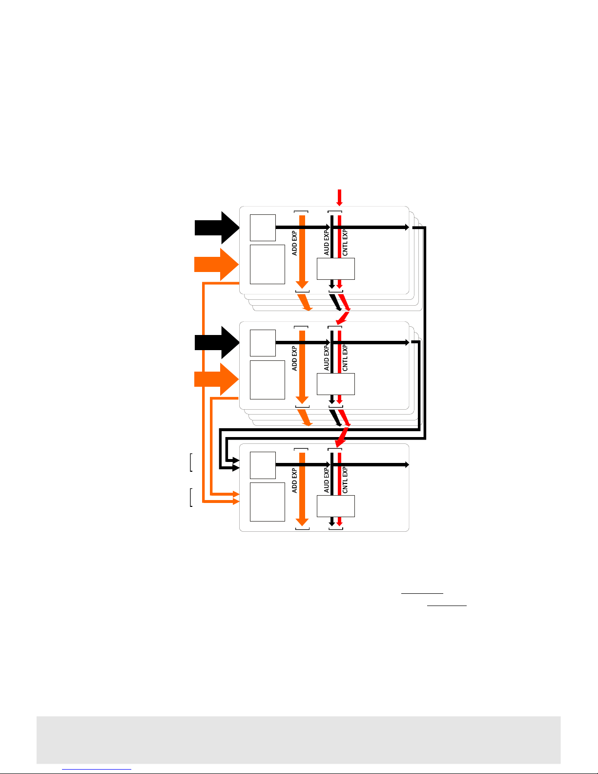
3.5Building a 64 input switcher
To create a 64x1 an extra audio switcher card is needed to act as a combiner module.
Note: With PL6 set to ON, each card in each 32x1 block has the 64x1 SEL address
lines bussed together using the address expansion connectors. The 64x1 SEL line is
also brought to pin 12 of the control connector on each rear connector. This address
line forms an active low select line for each 32x1 block, which then become the 2
channel select signals for combiner module by making external connections.
Technical Manual 19
4408Digital Audio 8x1 Switch
CONTROL
INPUTS
1 TO 32
AUDIO INPUTS
1 TO 32
1ST 32 X 1
AUDIO OUTPUT
VERTICAL PULSE
FROM VIDEO CARD
CONTROL
INPUTS
33 TO 64
AUDIO INPUTS
33 TO 64
CONTROL INPUTS
1-32 TO SEL 1
33-64 TO SEL 2
AUDIO INPUTS
1 AND 2
NOTE:
LAST CARD IN EACH
32X1 BLOCK HAS
EXPANSION JUMPERS
PL4 and PL5 SET
TO OFF
EXPANSION
CONFIG
PL9
8 X 1
32 X 1
PL7
PL10PL8
PL4,5: ON
PL11,12,13: ON
PL14: OFF
PL6 64x1
ON
PL3 MODE
BUTTON
64 X 1
AUDIO OUTPUT
NOTE:
COMBINER NEEDS
ONLY PL3 SET TO
BUTTON
EXPANSION
CONFIG
PL9
8 X 1
PL7
PL10PL8
PL6 64x1
ON
PL3 MODE
BUTTON
32 X 1
EXPANSION
CONFIG
PL9
8 X 1
PL7
PL10PL8
PL6 64x1
ON or OFF
PL3 MODE
BUTTON
COMBINER
2ND 32 X 1
AUDIO OUTPUT
PL4,5: ON
PL11,12,13: ON
PL14: OFF
NOTE:
LAST CARD IN EACH
32X1 BLOCK HAS
EXPANSION JUMPERS
PL4 and PL5 SET
TO OFF
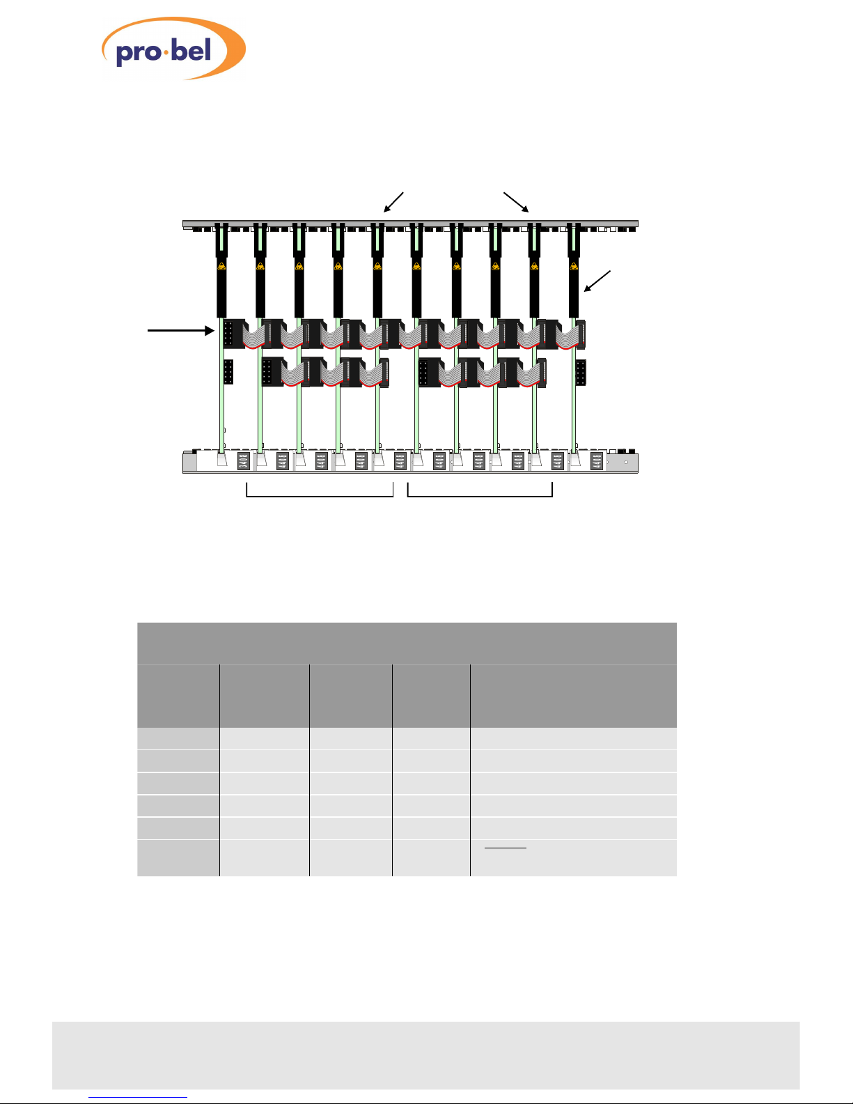
Building a synchronous 64x1 switch
Page 20
20
Issue 3
4408
Building a 64x1 synchronous switch
Jumper
1st 3 cards
in 32x1
block
Last card
in 32x1
block
Combiner
Function
PL3
BUTTONBUTTONBUTTONControl mode
PL4 & PL5
ONOFFOFFAnalogue signal expansion O/P
PL6
ONON ON or OFF64X1 select signal
PL11
ONOFFOFFDISOUT, priority switching signal
PL12
ONOFFOFFCLK I/O, output clock
PL13
ONONON
FTLOGIC, synchronous switching
mode
4
3
0
8
4
4
0
8
4
4
0
8
4
4
0
8
4
4
0
8
4
4
0
8
4
4
0
8
4
4
0
8
4
4
0
8
4
4
0
8
VID/CNTL
EXPANSION
COMBINER
LAST CARD IN 32X1 BLOCKS
VERT SYNC
ADDRESS
EXPANSION
1ST 32 X 1 BLOCK
2ND 32 X 1 BLOCK
Source expansion with vertical sync reference
Page 21
Technical Manual 21
4408Digital Audio 8x1 Switch
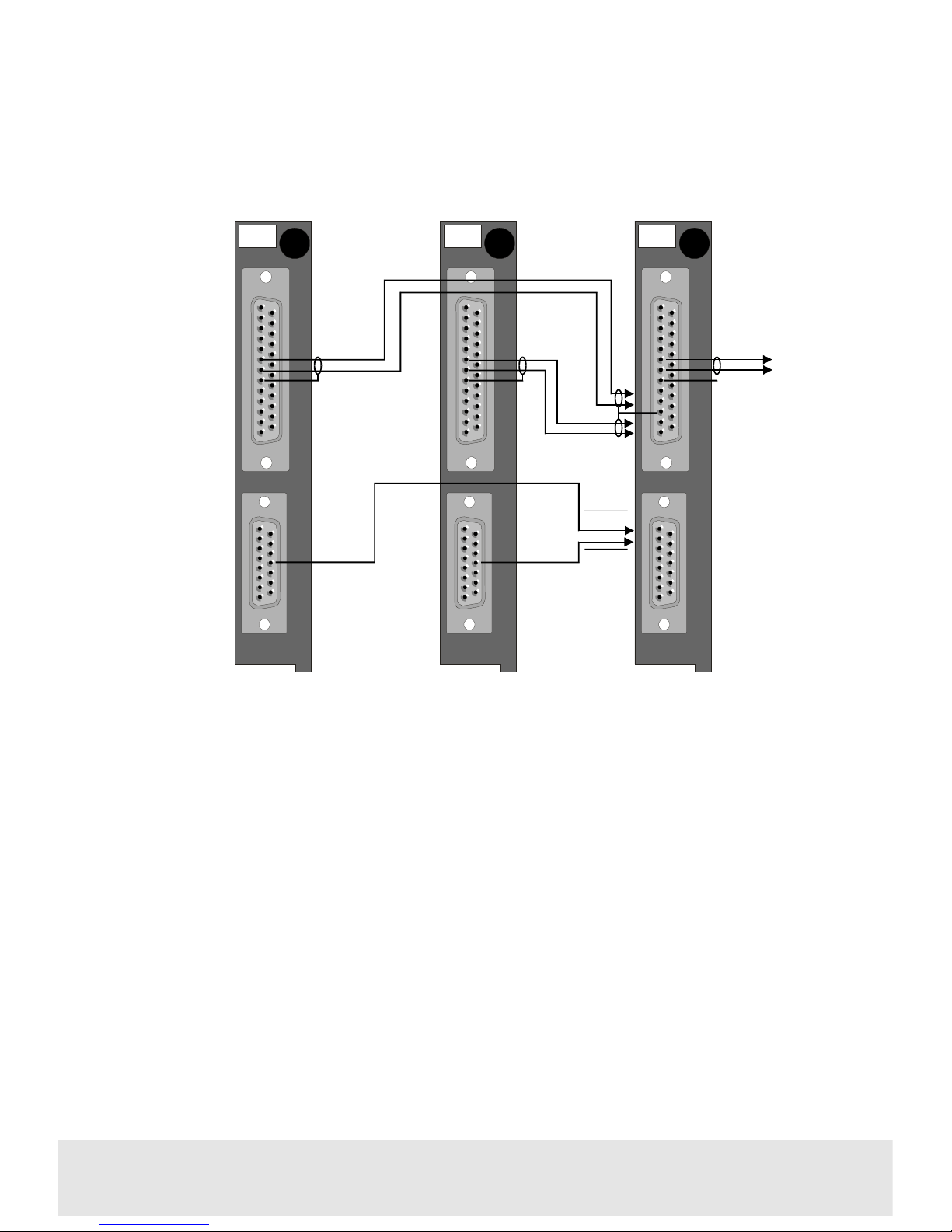
Combiner wiring for 64x1 expansion using balanced I/O
K4408
.2B
S
I
G
N
A
L
I
/
O
C
O
N
T
R
O
L
K4408
.2B
S
I
G
N
A
L
I
/
O
C
O
N
T
R
O
L
SEL 1
SEL 2
Any card in 1st
32x1 block
Any card in 2nd
32x1 block
Combiner
I/O and CNTL
K4408
.2B
S
I
G
N
A
L
I
/
O
C
O
N
T
R
O
L
1
9
10
1
25
25
25
12
13
64x1 O/P
6
7
1
32x1 O/P
32x1 O/P
8
6
7
8
6
7
8
1
15
1
2
12
15
12
1
15
A3 EXT/
64x1
A3 EXT/
64x1
Page 22
22
Issue 3
4408
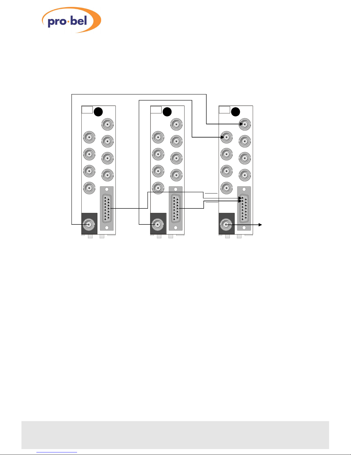
Combiner wiring for 64x1 expansion using unbalanced I/O
K4408
.3U
AES OUT
7
5
3
1
8
6
4
2
CONTROL
AES IN
K4408
.3U
AES OUT
7
5
3
1
8
6
4
2
CONTROL
AES IN
K4408
.3U
AES OUT
7
5
3
1
8
6
4
2
CONTROL
AES IN
SEL 1
SEL 2
Any card in 1st
32x1 block
Any card in 2nd
32x1 block
Combiner
I/O and CNTL
64x1 O/P
32x1 O/P
32x1 O/P
1
15
1
2
12
A3 EXT/
64x1
15
12
1
15
A3 EXT/
64x1
Page 23
3.6Using the 4408 with the 4405
re-framer
It is possible that bitstream corruption may occur when switching inputs. This may
occur even if all signals are co-timed and referenced to video and when the 4408
uses a vertical switching reference derived from the same reference.
Bitstream corruption could cause downstream equipment to lose lock briefly,
resulting in audible defects. The 4405 detects the corruption and inserts mute audio
samples whilst maintaining a constant bitsream.
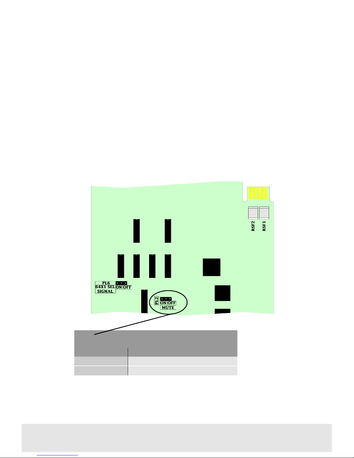
The 4408 can be configured to always produce a gap in the output bitsream,
guaranteeing that the re-framer will see a disturbance and re-frame.
Please refer to the 4405 re-framer manual for further details.
Technical Manual 23
4408Digital Audio 8x1 Switch
PL2 Switch mute
positionfunction
ON
Bitstream gap forced during input switch
OFF
Normal
Page 24

4 Trouble shooting
The green card edge POWER LED is not lit
•
check the PSU indicator to confirm that there is power to the frame
• check the resettable fuses protecting the card - do this by removing the power
to the card for about 30 seconds then restoring the power
•
if necessary, refer to the power supply trouble shooting guide in the appropriate
ICON rackframe manual section
There is no output signal
•
ensure that the green power LED on the front of the card is lit
• check that the inputs are connected to the rear panel and a valid signal is present
•
verify that the correct channel is selected - the LED on the button panel should
show the same channel number as the CHAN SEL LED on the front of the 4408
module
•
check the output connection from the rear panel to the monitoring device and
the output cable
• ensure that the cable wiring and jumper link settings are correct for the
configuration used
The button panel will not select a different input
•
ensure that the jumper PL3 is correctly set to ‘BUTTON’ on all modules
• check that the expansion cables are correctly installed
•
check that another, higher numbered, input is not permanently selected
The output signal is corrupted
•
check that jumpers PL4 and PL5 are set correctly for the configuration
• ensure all expansion cables are installed correctly
In a 64x1 configuration, only half of the inputs are being routed
•
check that the 64x1 SEL line (PL6 ON) from pin 12 of CNTL on the rear panel from
each 32x1 block is properly connected to the SEL 1 and SEL 2 pins of the
combiner CNTL connector
•
check that an audio output is connected from each 32x1 block to the first two
combiner inputs
24
Issue 3
4408
Page 25

Technical Manual
25
4408Digital Audio 8x1 Switch
Page 26

5 COSMOS status monitoring
If the frame is equipped with a COSMOS controller card the following parameters will
be reported back to the COSMOS status monitoring system:
• module present
• power OK
•
input selected
In addition, the module is programmed with the following information, which can be
read by the status monitoring controller:
• module type
•
module bar code
•
module issue no
For further details of the Pro-Bel status monitoring system please refer to the
COSMOS status monitoring manual.
26
Issue 3
4408
Page 27

Technical Manual 27
4408Digital Audio 8x1 Switch
Page 28

6 Specification
Inputs
Number and type:8, balanced, transformer coupled to AES3-1992 or
unbalanced to AES3-id
Termination:
High, 75Ω or 110Ω
Outputs
Number and type:1, transformer coupled, balanced to AES3-1992 or
unbalanced to AES3-id
Performance
Bitstream integrity:Transparent to all AES/EBU parameters
Sample rate:32 to 54kHz
Switch transition:Normal or mute (jumper selectable)
Control
Battery supply voltage:
(BATTSUP)
If supplied by external DC source -3.5V to 12V
External field trigger:
(FTLOGIC)
Allows switch transition to be synchronised to
external source
BUTTON mode:Max current sunk by select line 8mA for 24V
external supply, 4mA for +12V on board supply.
(LAMPSUP 12V @ 100mA maximum)
BINARY mode:3 bit binary address, 12V CMOS positive logic
convention
Indications
Power:Green LED
Input selected:8 x yellow LEDs
Temperature range
Operating:
0° to +40°C
Storage:
-10°C to +70°C
28
Issue 3
4408
Page 29

Technical Manual 29
4408Digital Audio 8x1 Switch
Page 30

7 Ordering Information
ICO-4408-2B008x1 Digital Audio Switch with 20mm rear panel
providing balanced AES3 interfaces
ICO-4408-3U008x1 Digital Audio Switch with 30mm rear panel
providing unbalanced AES3 interfaces
30
Issue 3
4408
 Loading...