

Page 1
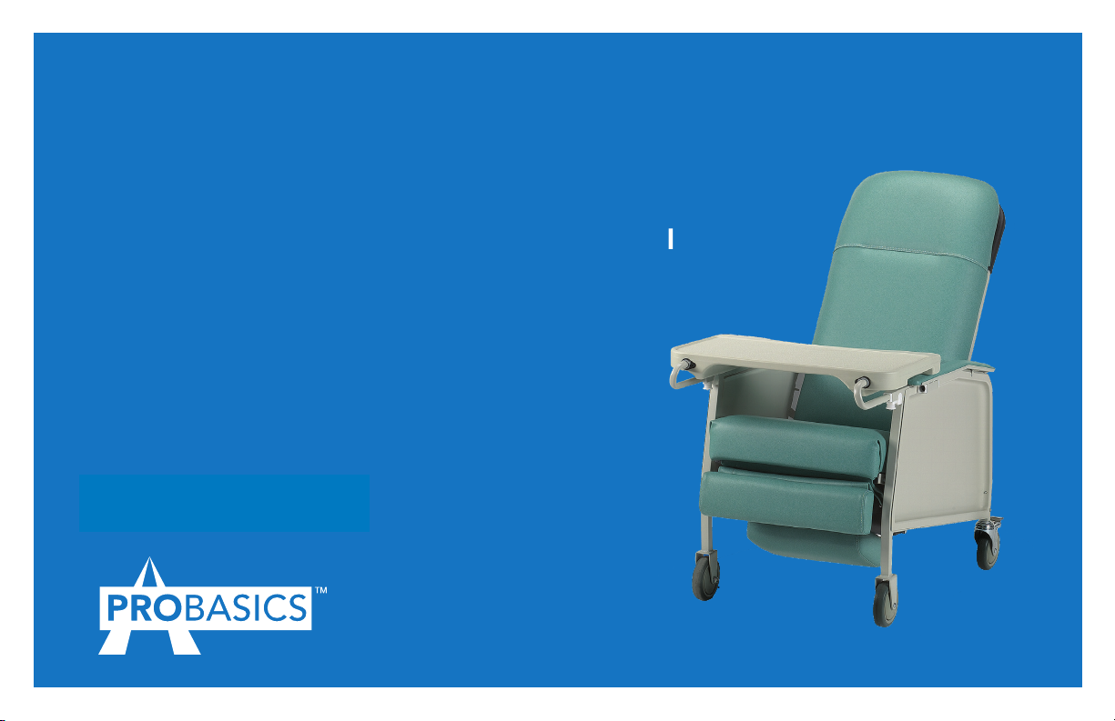
Three-Position Recliner
Owner’s Operation and Maintenance Manual
For use with Item #PB6074
DEALER: This manual MUST be given to the user
of the product.
USER:
• BEFORE using this product, read this manual
in its entirety and save for future reference.
• Initial and ongoing maintenance MUST be
performed only by qualied personnel.
For more information regarding ProBasics
products, parts, and services, please visit
www.compasshealthbrands.com
Page 2

WARNINGS
WARNINGS
NEVER USE THIS PRODUCT OR ANY AVAILABLE OPTIONAL
EQUIPMENT WITHOUT FIRST COMPLETELY READING
AND UNDERSTANDING THESE INSTRUCTIONS AND ANY
ADDITIONAL INSTRUCTIONAL MATERIAL SUCH AS OWNER’S
MANUALS, SERVICE MANUALS OR INSTRUCTION SHEETS
SUPPLIED WITH THIS PRODUCT OR OPTIONAL EQUIPMENT.
IF YOU ARE UNABLE TO UNDERSTAND THE WARNINGS,
CAUTIONS OR INSTRUCTIONS, CONTACT A HEALTHCARE
PROFESSIONAL, DEALER OR TECHNICAL PERSONNEL
BEFORE ATTEMPTING TO USE THIS EQUIPMENT - OTHERWISE,
INJURY OR DAMAGE MAY OCCUR.
ACCESSORIES WARNINGS
PROBASICS PRODUCTS ARE SPECIFICALLY DESIGNED
AND MANUFACTURED FOR USE IN CONJUNCTION WITH
PROBASICS ACCESSORIES. ACCESSORIES DESIGNED BY
OTHER MANUFACTURERS HAVE NOT BEEN TESTED BY
PROBASICS AND ARE NOT RECOMMENDED FOR USE WITH
PROBASICS PRODUCTS.
PROBASICS MOBILE RECLINER TIE-DOWN RESTRAINTS
Compass Health Brands recommends that Mobile Recliner users NOT
be transported in vehicles of any kind while in mobile recliners. Currently,
the US Department of Transportation (DOT) has not approved any tiedown systems for transportation of a user while in a ProBasics Mobile
Recliner, in a moving vehicle of any type.
ProBasics Mobile Recliners have not been designed and/or tested for
seating surfaces or vehicle chairs for occupant use within any type of
vehicle.
Compass Health Brands recommends that users of Mobile Recliners
should always be transferred into appropriate, DOT-approved seating
in vehicles for transportation and use be made of the restraints made
available by the auto industry. Presently, Compass Health Brands
does not have any participation in the manufacture of Mobile Recliner
transportation systems.
MAINTENANCE
Maintenance MUST be performed only by qualied personnel.
ProBasics Mobile Recliners should be regularly inspected for worn/
damaged mechanism guards. Chairs with damaged guards MUST be
removed from service and repaired.
2
Page 3

TABLE OF CONTENTS
LABEL LOCATION ................................... 4
SPECIAL NOTES ..................................... 4
PRODUCT PARAMETERS .............................. 5
SECTION 1—WARNINGS AND GENERAL GUIDELINES ...... 6
Service Information ...................................6
Operation Information ................................6
Weight Limitation ....................................7
Recline Option Operated by an Attendant ................7
SECTION 2—SAFETY INSPECTION ...................... 8
Safety Inspection Checklists ............................8
SECTION 3—ASSEMBLY............................... 9
Assembling the Recliner ...............................9
SECTION 4—OPERATION ............................ 10
Reclining the Chair ..................................10
Positioning the Articulating Headrest....................10
Locking/Unlocking the Rear Wheels.....................11
Installing/Storing the Tray .............................11
Adjusting the Tray Position ............................11
SECTION 5—MAINTENANCE ......................... 12
Replacing the Back Cushion ...........................12
Replacing the Footrest Cushion ........................12
Replacing the Recline Mechanism Guard .................13
Replacing Position Lock Lever .........................14
Removing Position Lock Lever .........................14
Installing Position Lock Lever ..........................14
Replacing Casters ...................................14
Replacing Caster Assembly............................14
Replacing Caster Wheels .............................14
Replacing Plunger Release Knob .......................15
Removing/Installing the Side Panel .....................15
Removing Side Panels................................15
Installing Side Panel .................................16
Replacing the Armrest Cushion ........................16
Removing Armrest Cushion ...........................16
Installing Armrest Cushion ............................16
Cleaning the Upholstery ..............................17
LIMITED WARRANTY ..............................17-18
INDICATIONS FOR USE
This mobile recliner has been designed for use in the home or a clinical
environment where a user may need a more substantial seating platform.
Mobile recliners may be used with those who may require reclined
seating for the following reasons:
• Dialysis or chemo
• Same-day surgery
• Post-operative seating
• Cardiac or outpatient care
• Arthritis
• Neuromuscular disorders
• Limited of reduced mobility
• Other conditions which may necessitate the need for a recliner chair
3
Page 4
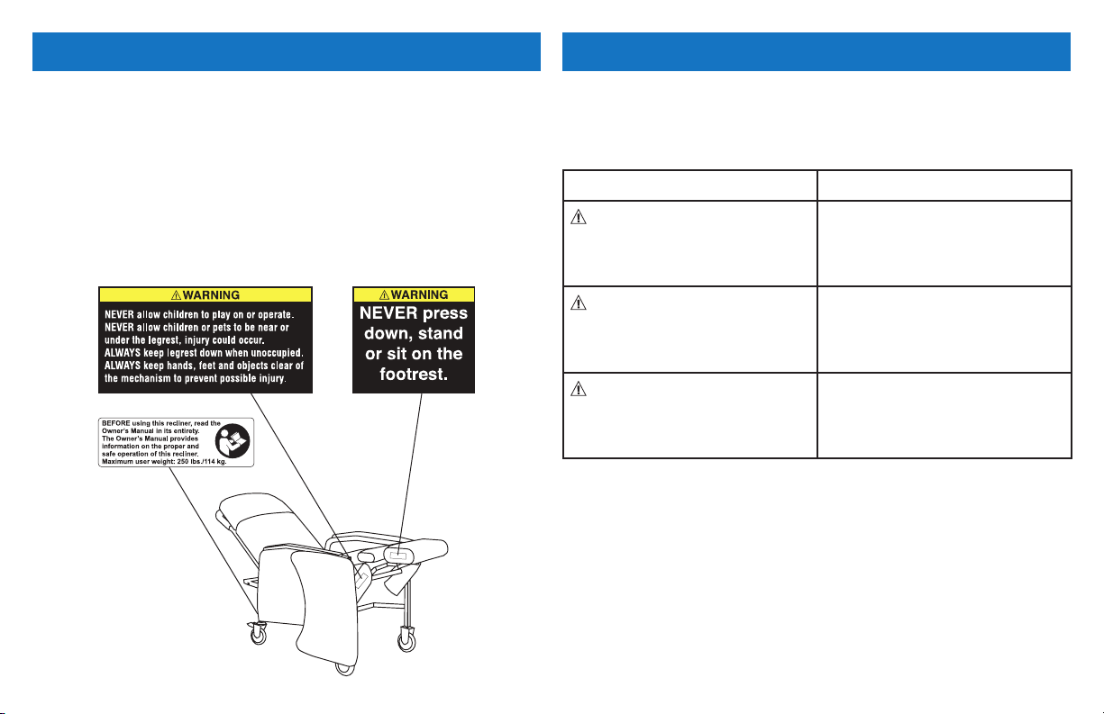
LABEL LOCATION SPECIAL NOTES
NEVER allow children to operate the recliner. The legrest lowers down
upon closing so that a child could possibly be severely injured.
NEVER allow children or pets to play on or under the recliner. The
legrest lowers down upon closing so that a child or pet could possibly be
severely injured.
When unoccupied ensure the legrest is down. Keep hands and feet clear
of mechanism. NEVER press down or stand on the footrest.
1143177 Rev. A - 4/25/06
Signal words are used in this manual and apply to hazards or unsafe
practices which could result in personal injury or property damage. Refer
to the following table for denitions of the signal words.
SIGNAL WORD MEANING
DANGER Danger indicates an imminently
hazardous situation which, if not
avoided, will result in death or
serious injury.
WARNING Warning indicates a potentially
hazardous situation which, if not
avoided, could result in death or
serious injury.
CAUTION CAUTION calls attention to a
low risk; indicates some injury or
property damage may result if
proper precautions are not taken.
NOTICE
THE INFORMATION CONTAINED IN THIS DOCUMENT IS SUBJECT
TO CHANGE WITHOUT NOTICE.
4
NOTE: Updated versions of this manual are available on www.compasshealthbrands.com.
Page 5

TYPICAL PRODUCT PARAMETERS
MODEL NO. PB6074
OVERALL HEIGHT: 47 inches
OVERALL WIDTH: 28 inches
OVERALL DEPTH UPRIGHT: 41 inches
OVERALL DEPTH RECLINE: 68 inches
SEAT WIDTH: 19 inches
SEAT DEPTH: 20 inches
SEAT-TO-BACK HEIGHT: 34 inches
SEAT-TO-FLOOR HEIGHT: 21 inches
SEAT ANGLE RANGE: 11° - 35°
BACK ANGLE RANGE: 38° - 61°
OVERALL TRAY LENGTH
AND WIDTH:
WEIGHT LIMITATION: 250 lbs
PRODUCT WEIGHT: 91 lbs
SHIPPING WEIGHT: 105 lbs
25½ x 15 inches
MODEL NO. PB6074WD
OVERALL HEIGHT: 47 inches
OVERALL WIDTH: 32 inches
OVERALL DEPTH UPRIGHT: 43 inches
OVERALL DEPTH RECLINE: 68 inches
SEAT WIDTH: 22¾ inches
SEAT DEPTH: 20½ inches
SEAT-TO-BACK HEIGHT: 34 inches
SEAT-TO-FLOOR HEIGHT: 22 inches
SEAT ANGLE RANGE: 14° - 38°
BACK ANGLE RANGE: 36° - 61°
OVERALL TRAY LENGTH
AND WIDTH:
WEIGHT LIMITATION: 400 lbs
PRODUCT WEIGHT: 91 lbs
SHIPPING WEIGHT: 107 lbs
N/A
5
Page 6

SECTION 1—WARNINGS AND GENERAL GUIDELINES
SECTION 1 - WARNINGS AND GENERAL GUIDELINES contains
important information for the safe operation and use of this product.
Check all parts for shipping damage. In case of damage, DO NOT USE.
Contact Carrier/ Dealer for further instructions.
Every month, inspect all pivot points and fasteners for wear. If the metal
is worn, DO NOT USE, the parts MUST be replaced. Refer to pg. 8 &
12 of this manual for proper maintenance and inspection guidelines.
Regular maintenance of the mobile recliner and accessories is necessary
to assure proper and safe operation. Ensure that casters are free of
debris.
ALWAYS keep hands and ngers clear of moving parts to avoid injury.
NEVER use near an open ame or heat source, as all upholstery
materials, even though treated with ame retardant, can ignite when
exposed to open ame.
Rear caster wheels MUST be locked during user transfer to or from
recliner and while tilting and/or reclining or inclining (sitting up).
Casters and axle bolts require inspection every month to check for
tightness and wear.
NEVER enter or exit the recliner when footrest is elevated.
NEVER sit on the footrest when recliner is extended. The recliner will
tip and bodily injury may occur.
6
NEVER push or pull footrest to position the recliner.
NEVER stand on the footplates. When getting in or out of the
wheelchair, make sure that the footplates are in the upward position or
swing the footrests towards the outside of the wheelchair.
NEVER place hands or feet into any openings when adjusting the
recliner. Attendant or care provider should always verify placement of
user ’s hands and feet prior to adjusting the recliner. Failure to do so
may result in serious bodily injury.
Operation of recliner with missing or broken footrest or recline
mechanism guards may result in bodily injury. Periodic inspection of the
footrest guard and recline mechanism guard MUST be made monthly.
Torn, cracked or otherwise damaged guards MUST be replaced prior to
use. Recliner MUST be removed from service until replacement guards
are installed.
NEVER lift the recliner by the footrest. Lifting by means of the footrest
may result in injury to the user and/or damage to the recliner.
NEVER attempt to stop the recliner with the wheel locks, while in
motion. Wheel locks are not brakes.
Before attempting to transfer in or out of the recliner, every precaution
should be taken to reduce the gap distance. Turn the recliner toward
the object you are transferring onto. When transferring to and from
the recliner, ALWAYS engage both wheel locks. Special care MUST BE
taken with people that have physical limitations and who may require an
assistant.
Page 7

SECTION 1— WARNINGS AND GENERAL GUIDELINES (CONT)
NEVER traverse, climb or go down ramps or slopes greater than 9°
with a user seated in the chair.
ProBasics products are specically designed and manufactured for use
in conjunction with ProBasics accessories. Accessories designed by
other manufacturers have not been tested by Compass Health Brands
or the manufacturer and are not recommended for use with ProBasics
products.
NEVER allow children to operate the recliner. The legrest lowers down
upon closing so that a child could possibly be severely injured.
NEVER allow children or pets to play on or under the recliner. The
legrest lowers down upon closing so that a child or pet could possibly
be severely injured.
When unoccupied ensure the legrest is ALWAYS down. Keep hands
and feet clear of mechanism. NEVER press down or stand on the
footrest.
WEIGHT LIMITATION
The weight limitation for ProBasics Mobile Recliners is 250 lbs
(113.6 kg). The weight limitation for model PB6074WD Wide Recliner is
400 lbs (181.44 kg). The tray for model PB6074 has a weight limitation
of 40 lbs (18.2 kg).
RECLINE OPTION OPERATED BY AN ATTENDANT
Test the recline feature of the recliner rst without an occupant to
ensure the gas cylinder is operational. NEVER operate the recline
option if the gas cylinder is not operational.
ALWAYS make sure that the recliner is stable before using the recline
option.
Make sure the patient is properly positioned in the recliner before
reclining or inclining to maintain maximum stability and safety.
When returning the occupant of the recliner to the full upright position,
more body strength will be required for approximately the last twenty
degrees of incline (sitting up). Make sure to use proper body mechanics
(use your legs) or seek assistance to avoid injury.
Physical limitations of a user and larger occupants of the recliner can
present conditions that can injure the assistant. When in doubt, ensure
that additional assistants are present before operating the recline
feature.
This recliner is intended for indoor use only.
7
Page 8

SECTION 2—SAFETY INSPECTION
NOTE: Every six months or as necessary take your recliner to a qualied
dealer for a thorough inspection and servicing. Regular cleaning
service and inspection will reveal loose or worn parts and enhance the
smooth operation of your recliner. To operate properly and safely, your
recliner must be cared for appropriately as any other vehicle. Routine
maintenance will extend the life and efciency of your recliner.
SAFETY INSPECTION CHECKLISTS
WARNING
As with any transport device, casters should be checked periodically for
cracks and wear and should be replaced as necessary.
Initial adjustments should be made to suit your personal body structure
needs and preference. Thereafter follow these maintenance procedures:
INSPECT/ADJUST BEFORE FIRST USE
❑ Ensure that the recliner rolls straight (no excessive drag or pull to
one side).
❑ Ensure seat, back and/or armrest upholstery have no rips and do not
sag. Replace if necessary.
❑ Ensure that the seat upholstery is fastened to the seat frame.
❑ Clean seat upholstery and armrests.
❑ Inspect caster assembly to ensure it has proper tension when caster
is spun. Caster should come to a gradual stop.
❑ Loosen/tighten caster locknut if wheel wobbles noticeably or binds
to a stop.
❑ Ensure that the caster assembly is free from debris.
❑ Inspect for any loose hardware on the recliner.
❑ Check that all labels are present and legible (as illustrated on p.4).
Replace if necessary.
8
INSPECT/ADJUST WEEKLY
❑ Ensure that the seat upholstery is fastened to the seat frame.
❑ Ensure seat, back and/or armrest upholstery have no rips and do not
sag. Replace if necessary.
❑ Ensure that the caster assembly is free of debris.
INSPECT/ADJUST MONTHLY
❑ Ensure that the recliner rolls straight (no excessive drag or pull to
one side).
❑ Ensure that the seat upholstery is fastened to the seat frame.
❑ Inspect caster assembly to ensure it has proper tension when caster
is spun. Caster should come to a gradual stop.
❑ Loosen/tighten caster locknut if wheel wobbles noticeably or binds
to a stop.
❑ Inspect for any loose hardware on the recliner.
❑ Ensure recliner rolls straight (no excessive drag or pull to one side).
❑ Ensure seat, back and/or armrest upholstery have no rips and do not
sag. Replace if necessary.
❑ Clean upholstery and armrests.
❑ Check that all labels are present and legible. Replace if necessary.
❑ Inspect all pivot points and fasteners for wear. Replace if necessary.
Page 9
SECTION 3—ASSEMBLY
WARNING
After ANY adjustments, repair or service and before use, make sure
that all attaching hardware is tightened securely - otherwise injury or
damage may result.
ASSEMBLING THE RECLINER
WARNING
Tighten mounting screws securely. Failure to do so may result in bodily
injury or damage to the recliner.
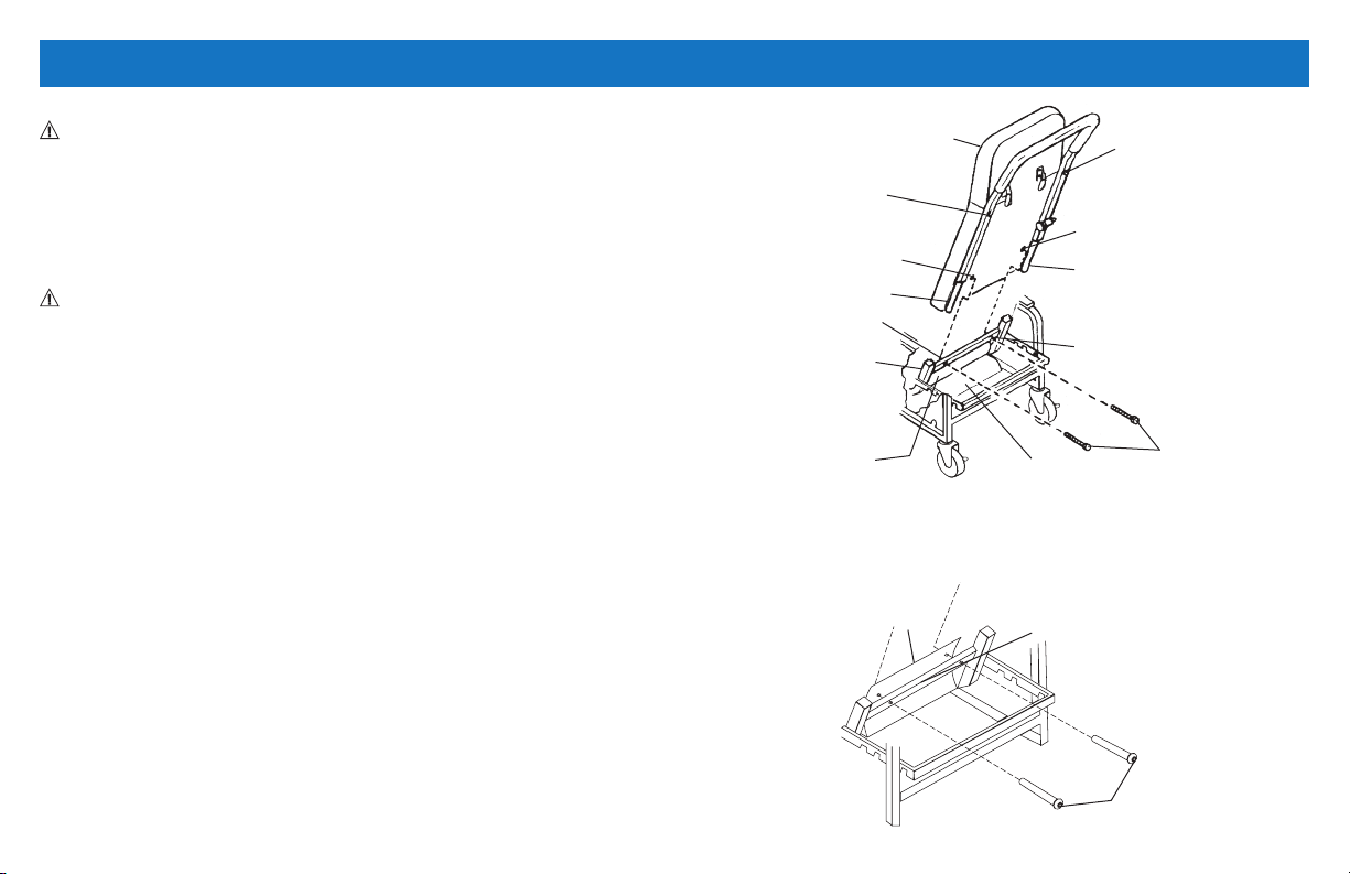
NOTE: For this procedure, refer to FIGURE 3.1 on this page.
1. Remove back frame with back cushion from its carton.
2. Lock the rear casters. Work from the rear of the recliner base.
NOTE: Ensure that footrest is in closed position before installing the
back frame with cushion.
3. Lift the chair back in an upright position behind the rear seat cross
brace.
4. Slide the back tubes into the open tube ends of the rear seat cross
brace.
5. Lift the plastic skirt mounted on the bottom of the seat and align
behind the rear seat frame crossbrace
(DETAIL “A”).
6. Align the holes in the skirt to the holes in the chair back by fastening
the hardware.
7. Securely tighten the two hex screws to secure the back cushion to
the back frame.
Back Frame with
Back Cushion
Hex Screw
Mounting Hole
Guide Tube
Mounting
Hole
Seat Frame
Rear Seat Frame
Crossbrace
Plastic Skirt
FIGURE 3.1 Assembling the Recliner
DETAIL “A” - Plastic Skirt
Plastic
Skirt
Rear Seat
Frame
Crossbrace
Hex Screw
Mounting Hole
Guide Tube
Mounting Hole
Hex
Head
Screws
Hex
Head
Screws
9
Page 10
SECTION 4—OPERATION
WARNING
After ANY adjustments, repair or service and BEFORE use, ensure
that all attaching hardware is tightened securely - otherwise injury or
damage may result.
CAUTION
Ensure that there is adequate room to operate the ProBasics Mobile
Recliner. There must be at least three feet clearance between the top of
the recliner back and the surrounding objects, otherwise damage to the
recliner and or surrounding property may occur.
RECLINING THE CHAIR
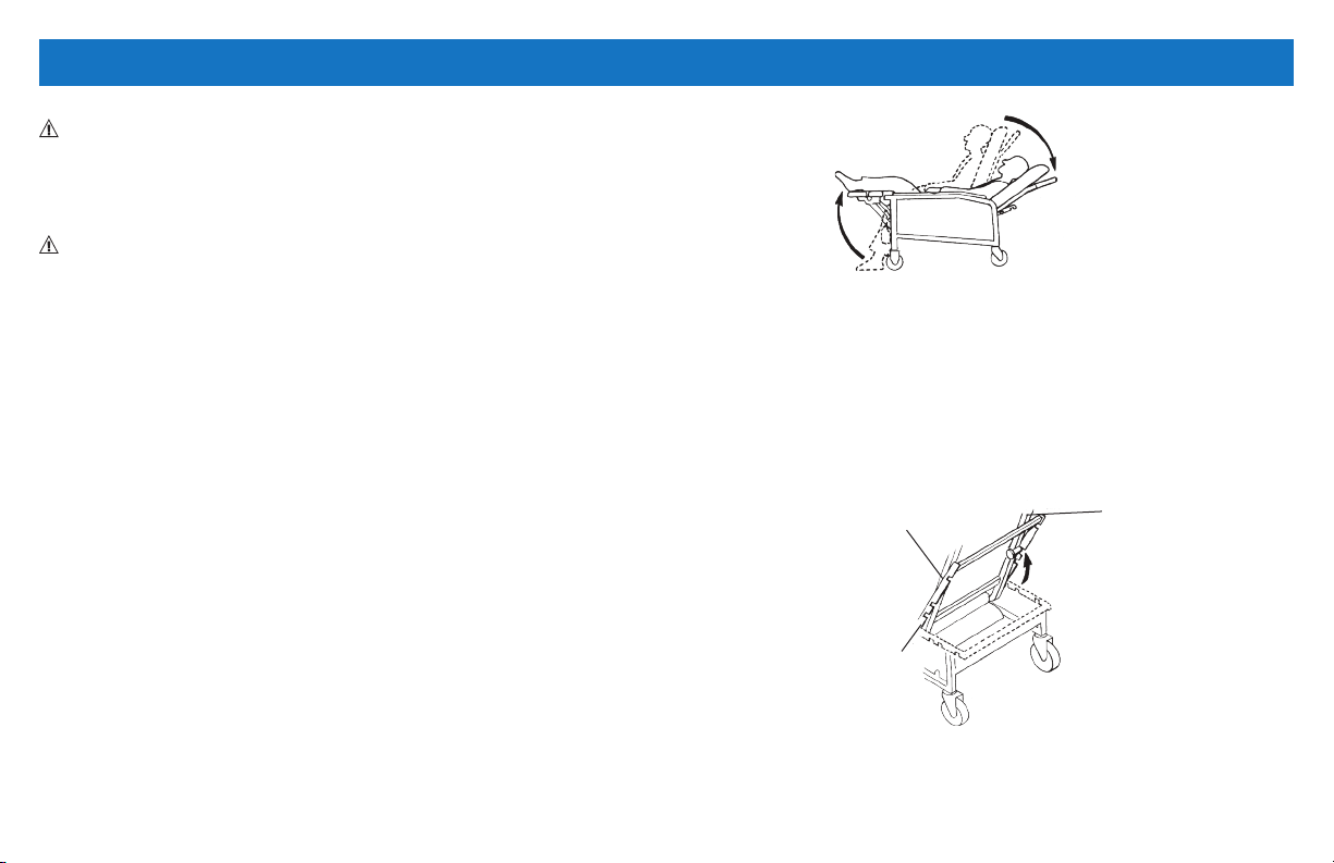
USER RECLINE
NOTE: For this procedure, refer to FIGURE 4.1.
NOTE: The chair cannot recline if the recline lock bar is engaged. An
assistant must rst swing recline lock bar up to the chair back and lock
into position.
1. While seated in the recliner, grip the armrests and simultaneously
lean body weight back and push forward with your arms until a
recline position reached.
NOTE: The footrest will lift automatically when the chair back reclines.
FIGURE 4.1 RECLINING THE CHAIR - USER RECLINE
ASSISTED RECLINE
NOTE: For this procedure, refer to FIGURE 4.2.
1. Swing recline lock bar up to chair back and lock into position.
2. Grasp the armrest with one hand and the push bar with the other
hand.
3. Push the back of the chair down slowly until a desired position is
reached.
Position
Lock Lever
Storage
Position
Back
Assembly
NOTE: The occupant should not be required to exert excessive force to
change recline positions. If the recliner exhibits difculty in reclining, an
attendant should be called for assistance.
10
FIGURE 4.2 RECLINING THE CHAIR - ASSISTED RECLINE
NOTE: The caregiver can set recline lock bar at one of the three locking
positions.
Page 11
SECTION 4—OPERATION (CONT)
LOCKING/UNLOCKING THE REAR WHEELS
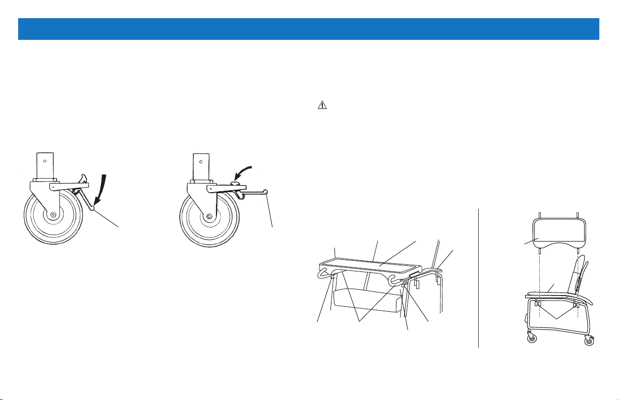
NOTE: For this procedure, refer to FIGURE 4.3.
1. Push down on the wheel lock mechanism to engage the wheel
locks.
2. Release the wheel locks by pushing the other side of the lock
mechanism downward.
LOCKING UNLOCKING
Wheel Lock
Mechanism
FIGURE 4.3 Locking/Unlocking the Rear Wheels
Wheel Lock
Mechanism
INSTALLING/STORING THE TRAY
NOTE: For this procedure, refer to FIGURE 4.4.
NOTE: Reverse this procedure to remove the tray.
WARNING: The tray has a weight limitation of 40 lbs. (18.2 kg).
1. Pull down on the plunger release knobs on both arms and twist
them ¼-turn to lock them in the open position.
2. Pull the tray up and clear from the hangers located on the side of
the recliner.
3. Align the alignment rods with the mounting brackets under the
armrests of the recliner.
4. Insert the alignment rods into the mounting brackets.
5. Slide the tray to the desired position until an audible click is heard.
Mounting Bracket
(Hidden from View)
Plunger
Release
Knob
Alignment
Rods
Tray
Plunger
Release Knob
DETAIL “A” FRONT VIEW
Armrest
Mounting
Brackets
DETAIL “B” SIDE VIEW
Tray
Armrest
Hangers
FIGURE 4.4 Installing/Storing the Tray
11
Page 12
SECTION 5— MAINTENANCE
WARNING
After ANY adjustments, repair or service and BEFORE use, make sure
that all attaching hardware is tightened securely - otherwise injury or
damage may result.
REPLACING THE BACK CUSHION
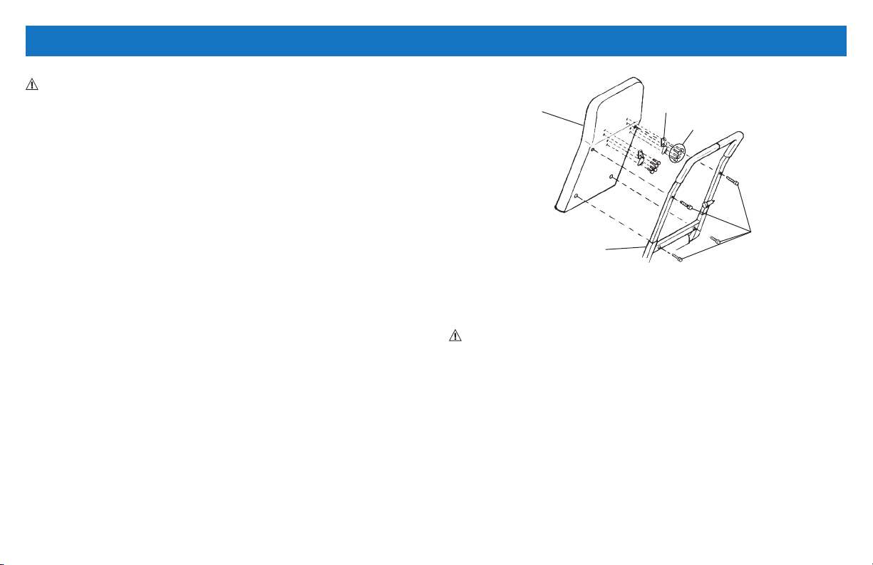
NOTE: For this procedure, refer to FIGURE 5.1.
REMOVING
1. Remove the four long hex screws that secure the back cushion to
the back frame.
2. Remove the four short hex screws that secure headrest bracket to
the back cushion.
3. Repeat for remaining headrest bracket.
Cushion
Back Frame
Headrest Bracket
Short Hex Screws
FIGURE 5.1 Replacing the Back Cushion
Long Hex
Screws
INSTALLING
1. Align back cushion with the back frame.
2. Install four long hex screws to secure the back cushion to the back
frame. Securely tighten.
3. Secure the headrest bracket to the back cushion with four short hex
screws.
4. Securely tighten. Repeat for remaining headrest bracket.
12
REPLACING THE FOOTREST CUSHION
WARNING
NEVER stand on the footrest or seat when entering or exiting the
recliner. The recliner will tip and bodily injury may occur.
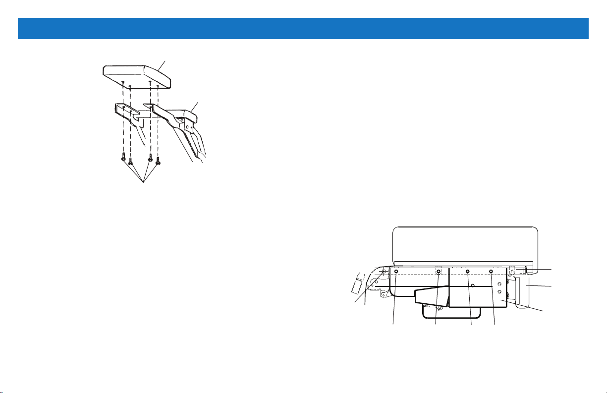
NOTE: For this procedure, refer to FIGURE 5.2 on page 13.
1. Recline the recliner to raise the footrest assembly. Refer to Reclining
the Chair on page 10.
2. Remove the four hex screws that secure the existing footrest
cushion to the recline mechanism.
3. Align the four mounting holes of the recline mechanism with the
four mounting holes of the new footrest cushion.
4. Using four hex screws, secure the footrest cushion to the recline
mechanism.
Page 13
SECTION 5— MAINTENANCE (CONT)
Footrest Cushion
Footrest
Assembly
Recline
Mechanism
Hex Screws
FIGURE 5.2 Replacing the Footrest Cushion
REPLACING THE RECLINE MECHANISM GUARD
NOTE: For this procedure, refer to FIGURE 5.3.
NOTE: Right and left sides are determined from the user’s seated
position.
1. Engage wheel locks.
2. Carefully tip recliner onto the right side. Be sure there are no
obstructions on or around the oor before doing this.
3. Remove the side panel. Refer to Removing/Installing the Side Panel
on page 15.
4. Remove four existing bolts A, B, C, and D from side frame as shown
in FIGURE 5.3.
5. Remove existing recline mechanism guard.
6. Position new recline mechanism guard against the side frame with
the folded edge down.
7. Align holes of new recline mechanism guard with holes on side
frame.
8. Secure new recline mechanism guard to side frame with bolts A, B,
C, and D. Securely tighten.
9. Install the side panel. Refer to Removing/Installing the Side Panel on
page 15.
10. Place chair in the upright position.
NOTE: If binding or pinching of recline mechanism guard occurs,
contact Compass Health Brands Corp. (see back panel of this manual).
11. Carefully tip recliner onto the left side. Ensure there are no
obstructions on or around the oor before doing this.
12. Repeat STEPS 3-10 to install remaining recline mechanism guard.
Side View
Rear of Chair Front of Chair
Side Frame
Footrest
DO NOT
Remove
This Bolt
Bolt A
Bolt DBolt CBolt B
Recline Mechanism
Guard
FIGURE 5.3 Replacing the Recline Mechanism Guard
13
Page 14
SECTION 5— MAINTENANCE (CONT)
REPLACING POSITION LOCK LEVER
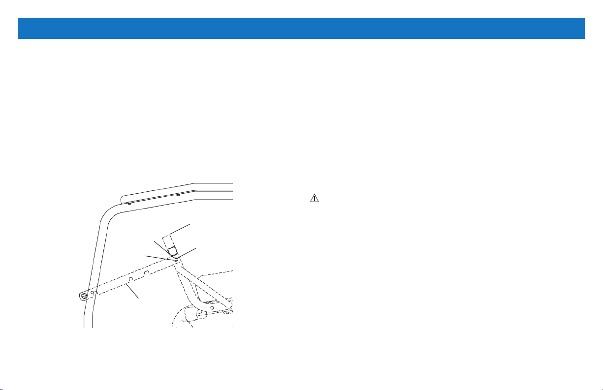
NOTE: For this procedure, refer to FIGURE 5.4.
REMOVING POSITION LOCK LEVER
1. Remove two screws, nylon washers and locknuts securing the
position lock lever to the seat frame.
INSTALLING POSITION LOCK LEVER
1. Secure the position lock lever to the seat frame with the two screws,
nylon washers and locknuts.
Seat Frame
14
Screw
Nylon
Washer
Position Lock
Lever
FIGURE 5.4 Replacing Position Lock Lever
Locknut
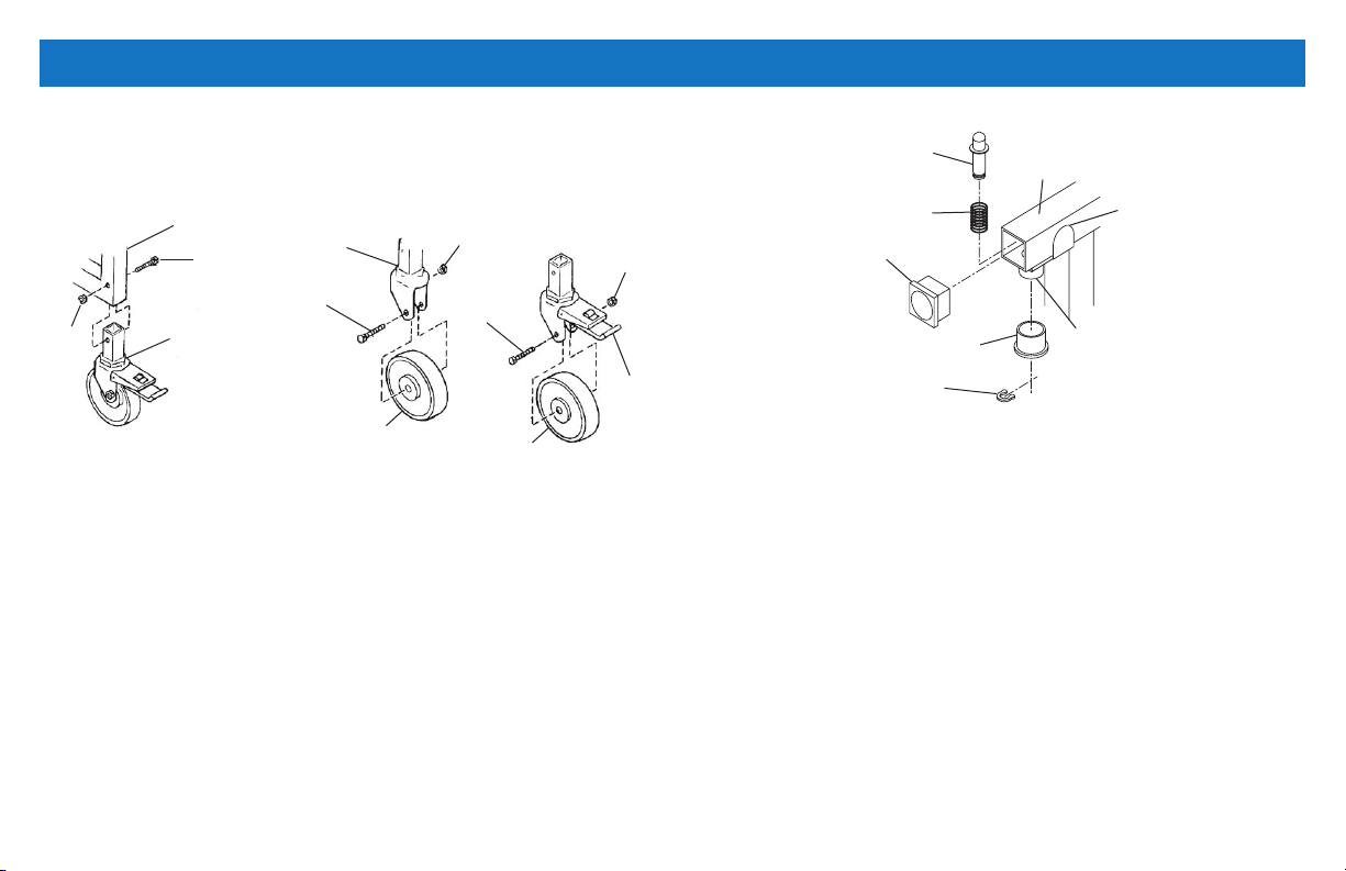
REPLACING CASTERS
REPLACING CASTER ASSEMBLY
NOTE: For this procedure, refer to DETAIL “A” of FIGURE 5.5.
1. Place the recliner on its side to gain access to the existing caster
assemblies.
2. Remove the hex screw and locknut that secures the caster assembly
to the recliner frame.
3. Align hole in caster insert with hole in recliner frame and install new
caster assembly.
4. Reinsert and tighten the hex head screw and nut.
5. Return the recliner to its upright position.
WARNING: Periodic inspection of the hex head screws and nuts
is recommended to ensure that they are tight. Time and usage may
cause them to become loose and could cause breakage of the caster
assemblies.
REPLACING CASTER WHEELS
NOTE: For this procedure, refer to DETAIL “B” of FIGURE 5.5
NOTE: When replacing the rear locking caster wheel, note the
orientation of the locking actuator and axle bolt for proper
reinstallation.
1. Remove axle bolt and locknut that secure the existing caster wheel
to the fork.
2. Remove existing caster wheel from fork.
3. Install the new caster wheel into the fork.
4. Install the axle bolt and locknut and tighten securely.
Page 15
SECTION 5— MAINTENANCE (CONT)
NOTE: The rear casters are locking/swivel casters and the front casters
are free-wheeling and non-pivotal.
DETAIL “A” - CASTER ASSEMBLY DETAIL “B” - CASTER WHEELS
Locknut
Recliner Frame
Hex Head
Screw
Caster
Insert
Fork
Axle Bolt
Caster Wheel
Nut
Axle Bolt
Caster Wheel
Locknut
Locking
Acruator
FIGURE 5.5 Replacing Casters
REPLACING PLUNGER RELEASE KNOB
NOTE: For this procedure, refer to FIGURE 5.6.
1. Remove glide from end of frame.
2. Remove retaining ring from end of plunger pin.
3. Slide plunger release knob off the plunger pin.
4. Lift plunger pin and spring out of the frame tube.
5. Insert new plunger pin and spring into the frame so that grooved
end of pin extends below the frame tube.
6. Place plunger release knob over the plunger pin.
7. Snap the retaining ring into groove of the plunger pin.
8. Replace the glide into the end of the frame.
Plunger Pin
Spring
Glide
Plunger Release Knob
Retaining Ring
Frame
Plastic
Keeper
Frame Tube
FIGURE 5.6 Replacing Plunger Release Knob
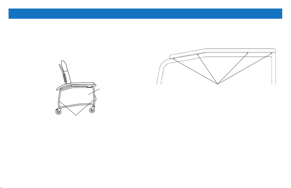
REMOVING/INSTALLING THE SIDE PANEL
NOTE: For this procedure, refer to FIGURE 5.7 on page 16.
REMOVING SIDE PANELS
1. Press the push buttons near the bottom of the right-side panel.
2. Hold the push buttons in while pulling the panel outward.
3. Repeat STEPS 1 and 2 for the other side panel.
15
Page 16
SECTION 5— MAINTENANCE (CONT)
INSTALLING SIDE PANEL
1. Slip the top of the right-side panel into the mounting tab.
2. Push the side panel upward until the side panel t into the side
frame.
3. Pop the side panel into position when the push buttons are visible,
through the push pin holes, near the bottom of the side frame.
Side
Panel
Push Buttons
FIGURE 5.7 Removing/Installing the Side Panel
REPLACING THE ARMREST CUSHION
NOTE: For this procedure, refer to FIGURE 5.8.
REMOVING ARMREST CUSHION
1. Remove four screws securing the armrest cushion to the
recliner frame.
2. Remove the armrest cushion from the recliner frame.
16
INSTALLING ARMREST CUSHION
1. Align the armrest cushion with the recliner frame.
2. Secure the armrest cushion to the recliner frame with the
four screws.
Screws
FIGURE 5.8 Replacing the Armrest Cushion
Page 17

SECTION 5— MAINTENANCE (CONT) LIMITED WARRANTY
CLEANING THE UPHOLSTERY
DANGER
When kerosene or naptha is being used, care should be exercised.
Keep away from re and ame and use only in a well-ventilated area.
WARNING
Carefully follow cleaning instructions provided with cleaning product.
NEVER use paint remover or any liquid brush cleaner.
NOTE: A variety of products may be used to clean the upholstery on
the recliner dependent upon the severity of the stain. The following list
should be helpful:
• Ordinary dirt stains: Clean upholstery with warm water and mild
detergent to remove supercial soil.
• Ground-in dirt stains: Use soft bristle brush and powdered cleanser
or similar detergent.
• Chewing gum: Scrape off carefully. Remove remainder with soap and
water.
• Paint or shoe polish: Remove immediately. Use a white cloth
dampened with soap and water.
• Excrement: Remove immediately. Clean with 1:10 mix of bleach and
water. Rinse area thoroughly.
NOTE: The durability of your chair can be improved by using a quality
paste wax periodically.
This warranty is extended only to the original purchaser/user of our
products. This warranty gives you specic legal rights and you may also
have other legal rights which vary from state to state.
Compass Health Brands warrants the products manufactured to be
free from defects in materials and workmanship for a period of three
years; and one year on the upholstery and Gas Spring Recline Cylinder
from the date of purchase. If within such warranty period any such
product shall be proven to be defective, such product shall be repaired
or replaced, at Compass Health Brands’ option. This warranty does
not include any labor or shipping charges incurred in replacement part
installation or repair of any such product. Compass Health Brands’
sole obligation and your exclusive remedy under this warranty shall be
limited to such repair and/or replacement.
For warranty service, please contact the dealer from whom you
purchased your ProBasics product. In the event you do not receive
satisfactory warranty service, please write directly to Compass Health
Brands at the address on the back cover, provide dealer’s name,
address, date of purchase, indicate nature of the defect.
Compass Health Brands will issue a serialized return authorization. The
defective unit or parts MUST be returned for warranty inspection using
the serial number, when applicable as identication within
30 days of return authorization date. Do not return products to our
factory without our prior consent. C.O.D. shipments will be refused;
please prepay shipping charges.
PLEASE NOTE: THE WARRANTY BELOW HAS BEEN DRAFTED
TO COMPLY WITH FEDERAL LAW APPLICABLE TO PRODUCTS
MANUFACTURED AFTER JULY 4, 1975.
17
Page 18

LIMITED WARRANTY (CONT)
LIMITATIONS AND EXCLUSIONS: THE FOREGOING WARRANTY
SHALL NOT APPLY TO SERIAL NUMBERED PRODUCTS IF
THE SERIAL NUMBER HAS BEEN REMOVED OR DEFACED,
PRODUCTS SUBJECTED TO NEGLIGENCE, ACCIDENT, IMPROPER
OPERATION, MAINTENANCE OR STORAGE, PRODUCTS
MODIFIED WITHOUT COMPASS HEALTH BRANDS’ EXPRESS
WRITTEN CONSENT (INCLUDING, BUT NOT LIMITED TO,
MODIFICATION THROUGH THE USE OF UNAUTHORIZED PARTS
OR ATTACHMENTS; PRODUCTS DAMAGED BY REASON OF
REPAIRS MADE TO ANY COMPONENT WITHOUT THE SPECIFIC
CONSENT OF COMPASS HEALTH BRANDS, OR TO A PRODUCT
DAMAGED BY CIRCUMSTANCES BEYOND COMPASS HEALTH
BRANDS’ CONTROL, AND SUCH EVALUATION WILL BE SOLELY
DETERMINED BY COMPASS HEALTH BRANDS. THE WARRANTY
SHALL NOT APPLY TO PROBLEMS ARISING FROM NORMAL
WEAR OR FAILURE TO ADHERE TO THE INSTRUCTIONS IN THIS
MANUAL.
THE FOREGOING WARRANTY IS EXCLUSIVE AND IN
LIEU OF ALL OTHER EXPRESS WARRANTIES. IMPLIED
WARRANTIES, IF ANY, INCLUDING THE IMPLIED WARRANTIES
OF MERCHANTABILITY AND FITNESS FOR A PARTICULAR
PURPOSE, SHALL NOT EXTEND BEYOND THE DURATION OF
THE EXPRESSED WARRANTY PROVIDED HEREIN AND THE
REMEDY FOR VIOLATIONS OF ANY IMPLIED WARRANTY SHALL
BE LIMITED TO REPAIR OR REPLACEMENT OF THE DEFECTIVE
PRODUCT PURSUANT TO THE TERMS CONTAINED HEREIN.
COMPASS HEALTH BRANDS SHALL NOT BE LIABLE FOR ANY
CONSEQUENTIAL OR INCIDENTAL DAMAGES WHATSOEVER.
SOME STATES DO NOT ALLOW EXCLUSION OR LIMITATION OF
INCIDENTAL OR CONSEQUENTIAL DAMAGE, OR LIMITATION
ON HOW LONG AN IMPLIED WARRANTY LASTS, SO THE ABOVE
EXCLUSIONS AND LIMITATIONS MAY NOT APPLY TO YOU.
THIS WARRANTY SHALL BE EXTENDED TO COMPLY WITH STATE
OR PROVINCIAL LAWS AND REQUIREMENTS.
18
Page 19

Manufactured for:
Compass Health Brands Corp.
Middleburg Heights, OH 44130
www.compasshealthbrands.com
800.376.7263 • Made in China
42-PB6074_01 © 2018
 Loading...