

Page 1
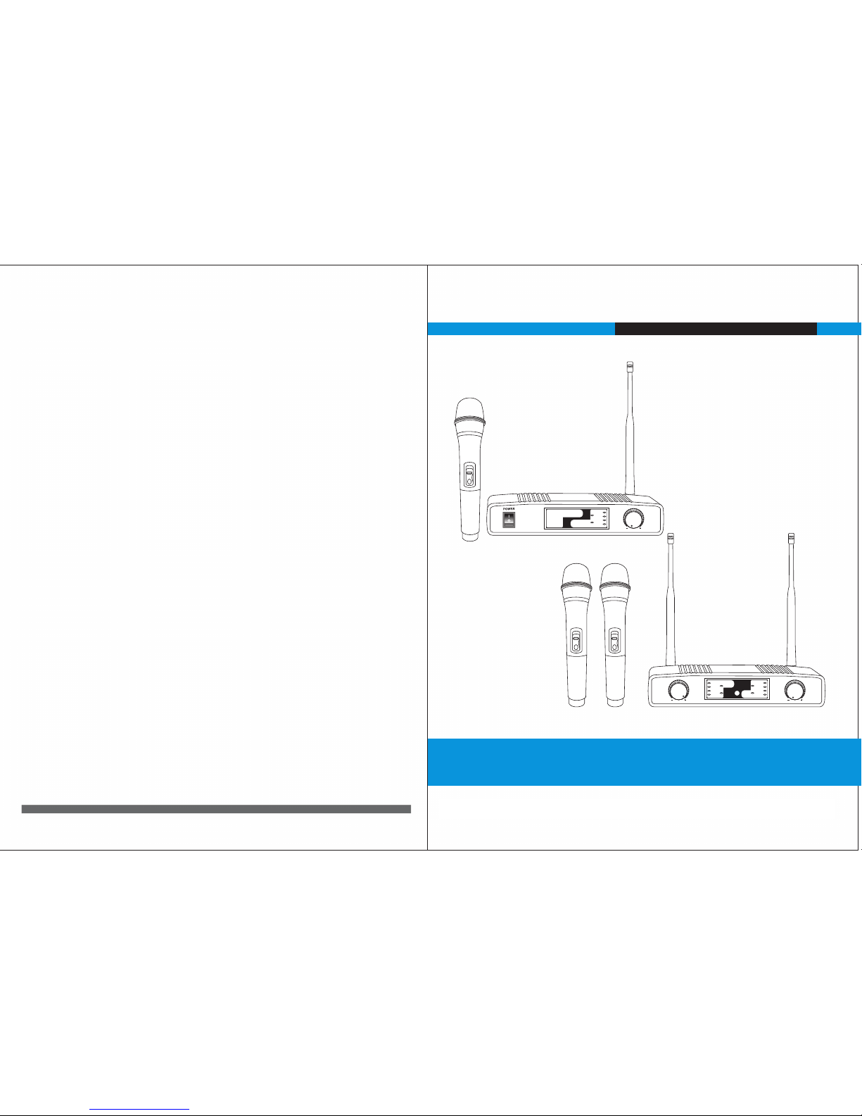
WIRELESS MICROPHONE SYSTEM
US ER G UI DE
VOLVOL
CHA
CH4
CH3
CH2
CH1
RF
AF
RF
AF
CHB
CH8
CH7
CH6
CH5
POWER
VOL
RF
AF
CH4
CH3
CH2
CH1
WIRELES S MICRO PHONE
OFF
OFFOFF
FCC Caution.
This device complies with part 15 of the FCC Rules. Operation is subject to the following two
conditions: (1)This device may not cause harmful interference, and (2) this device must accept
any interference received, including interference that may cause undesired operation.
Any Changes or modifications not expressly approved by the party responsible for compliance
could void the user's authority to operate the equipment.
Note: This equipment has been tested and found to comply with the limits for a Class B digital
device, pursuant to part 15 of the FCC Rules. These limits are designed to provide reasonable
protection against harmful interference in a residential installation. This equipment generates
uses and can radiate radio frequency energy and, if not installed and used in accordance with the
instructions, may cause harmful interference to radio communications. However, there is no
guarantee that interference will not occur in a particular installation. If this equipment does
cause harmful interference to radio or television reception, which can be determined by turning
the equipment off and on, the user is encouraged to try to correct the interference by one or
more of the following measures:
-Reorient or relocate the receiving antenna.
-Increase the separation between the equipment and receiver.
-Connect the equipment into an outlet on a circuit different from that to which the receiver
is connected.
-Consult the dealer or an experienced radio/TV technician for help.
* RF warning for Portable device:
The device has been evaluated to meet general RF exposure requirement. The device can be used
in portable exposure condition without restriction.
Page 2
Thank yo u for purchasi ng the Wirel ess Mi croph one Sy stem a nd con gratula tions on your cho ice.
The mode l is loaded with to p professional operating featu res and is the best price value availa ble in UHF wireless
systems.
This Wireless System contains the following components:
4 frequencies selec table each channel wireless receiver
8 fre quenc ies sel ectab le tran smitt er
Volu me Cont rol
Cha nnel In dicat or
RF LE D-Ind icate s stren gth of in comin g RF sign al
Aud io LED- Indic ates st rengt h of inco ming au dio sig nal
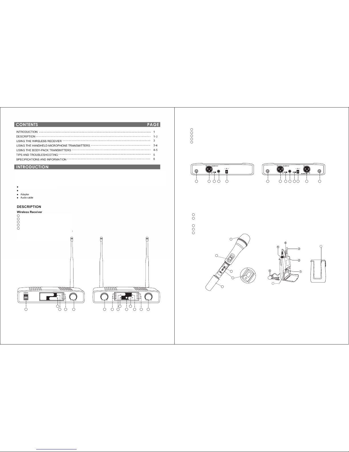
Pow er/ON /OFF sw itch
1
2
3
4
5
FIG URE 1
PAGE 1
VOL
RF
AF
CH4
CH3
CH2
CH1
WIRELESS M ICROP HONE
VOLVOL
CHA
CH4
CH3
CH2
CH1
RF
AF
RF
AF
CHB
CH8
CH7
CH6
CH5
POWER
11
2 23 3
4 4
55
2
1
3
4
REA R (FIGU RE 2)
Ant ennas -to rec eive si gnals f rom the t ransm itter
Bal ance- Outpu t
Fre quenc y Chann el Sele cting S witch
Unb alanc ed Audio a nd Mixe d Outpu t
Pow er-DC I nput
6
7
8
9
10
FIG URE 3
FIG URE 4
Body-P ack Transmitter (F IGURE 4)
1 .Battery Comp artment.
2.Power and Low Bat tery Indicator. When this red ligh t is glowing ,you have 20 minutes or less of useful ope rating time;
change the batt ery.
3. Antenna
4.Power and Mic MUT E ON/OFF Switch.
5.Microp hone Input Connector. Conne ctor provides connec tion to a variety of lavaliere and head set microphone cables .
6.Lavali er Microphone. Conde nser lavaliere microp hone supplied with a mount that cli ps onto a tie,lapel,or acous tic instrument.
7.Channe l Selector.
8. Belt Clip.
FIG URE 2
Handhe ld Microphone Tran smitter (FIG URE 3)
1 Cha nge to He ad
2 Pow er ON/O FF and MU TE ON/O FF Swit ch.
Whe n this re d light i s glowi ng, you h ave 20 mi nutes o r less of u seful o perat ing tim e; chan ge the ba ttery.
3 2 AA Alkal ine Bat tery. Pro vides p ower to t he micr ophon e trans mitte r. Typica l batte ry life i s 8 hours .
4 Bat tery Co ver. Take off t he batt ery cov er for tw o 1.5V al kalin e batte ries.
5 Cha nnel Se lecto r
OF
F
2
1
3
4
5
8
7
8
8
.
C
H
AN
N
EL
S
ELECT
8
7
8
PAGE 2
DC IN
12VDC
MIXED OUTPUT
87 65 43 21
CHANNEL CHANNEL
ANT.B ANT.A
DC IN
12VDC
MIXED OUTPUT
43 21
CHANNEL
ANT.B
43 21
6 6 67 7 78 89 1098 10
Page 3
1. Clip the body pack transmitter to your belt or guitar strap.
2. Connect the lavaliere microphone, headset or instrument adapter cable to the body-pack transmitter.
3. Select the transmitter to the right frequency.
4. Turn the transmitter POWER switch ON and MUTE switch OFF.
5. Check the RF Signal Indicator on the receiver to see if the RF signal is being received.
6. Begin speaking or playing your instrument.
7. During the performance or presentation, slide the MUTE ON/OFF switch to the ON position when the system is not being used.
8. When the performance or presentation is over, slide the transmitter MUTE ON/OFF switch to ON position and Power ON/OFF
switch to the OFF position to conserve battery power.
3. Inse rt two 1.5VAA alk aline bat teries in to the batt ery compa rtment. Two fr esh 1.5V al kaline ba tteries s hould typ ically pr ovide 8
hours o f perform ance time . Two fully char ged 1.2V Ni cad batte ries (1800 m A) should p rovide 12 ho urs of perf ormance t ime.
When th e LOW BATTERY lig ht on the tra nsmitte r turns on, yo u have 20 minu tes of less of u seful bat tery life r emainin g.
Chang e the batte ry at you firs t opportu nity.
IMPOR TANT: Carbon- zinc and zinc-chlor ide will not provid e adequat e power and ar e not recom mended.
4. S lid e the batt ery cov er ba ck on to th e mi c bod y.
1. Slid e the trans mitter Po wer ON/OF F switch to th e OFF positi on.
2. Pull u p on the OPEN si de of the batt ery compa rtment co ver, flip it op en, as shown i n FIGURE 8.
3. Inse rt fresh 1. 5VAA alkalin e batterie s into the ba ttery com partmen t as shown in Fi gure 8. Two 1.5VAA ba tteries sh ould prov ide 8
hours o f perform ance time . When the red L OW BATTERY ligh t on the tran smitter gl ows, you ha ve 20 minut es or less if use ful
batte ry life rem aining; c hange the ba ttery at yo ur first opp ortuni ty.
Oper ating Bod y-Pack Tra nsmitte rs
NOTE : The body-pack syst em is designed for use with othe r equipment, such as lav aliere microph ones, guitars , headset
micro phones, e tc. Conta ct your dea ler for deta ils on orde ring the pro per equip ment for yo ur needs.
Transmitter Battery Installatio n (FIGURE 8)
IMPOR TANT: Carbo n-zinc and zi nc-chlor ide batteri es will not prov ide adequat e power and are not re commende d.
4. Slid e the batte ry cover bac k onto the bo dy-pack tr ansmit ter.
3. Se lect th e trans mitfe r to the ri ght fre quenc y
4.
5.
6.
7.
8.
PAGE 4
OFF
OFF
FIG URE 5
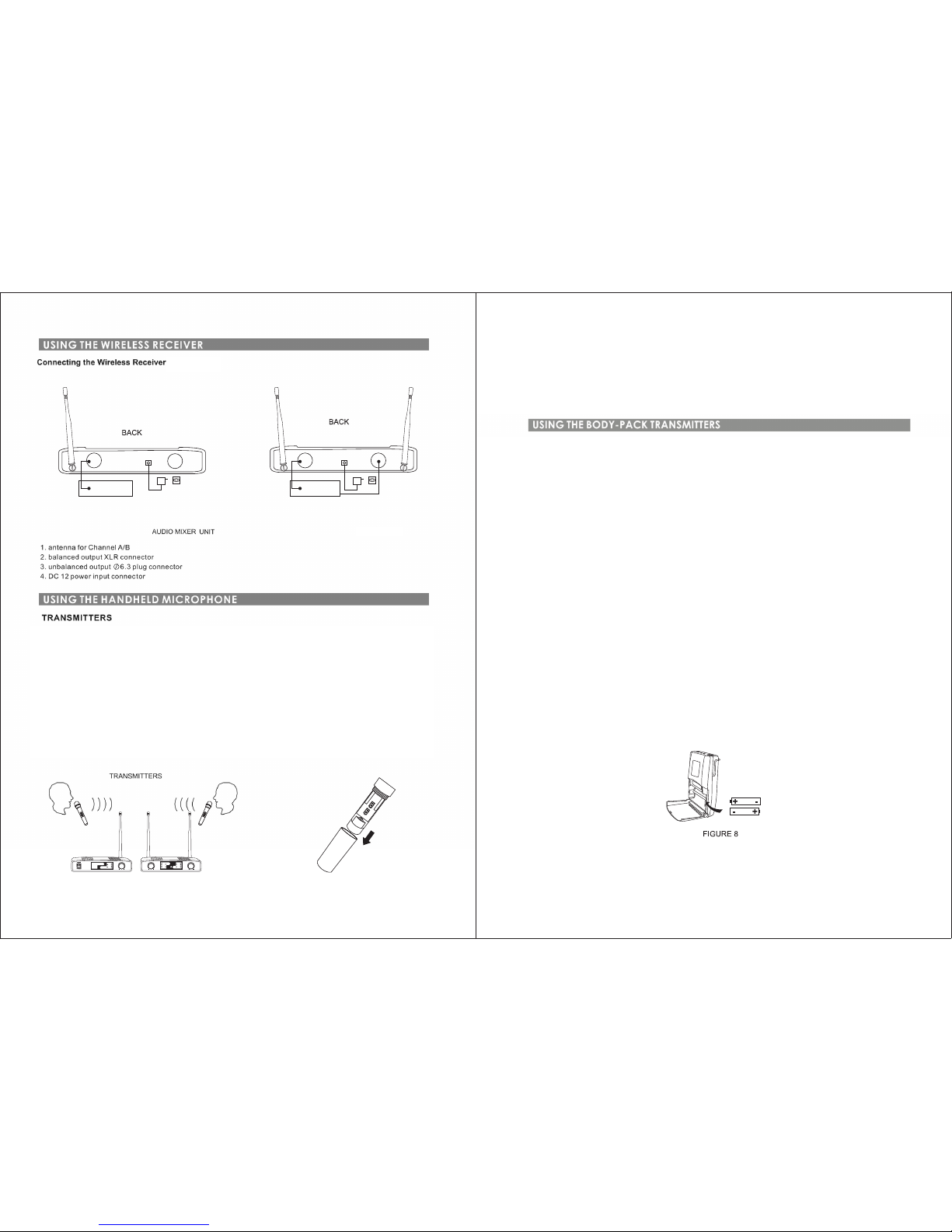
Operating the Hand Microp hone Transmitte rs (FIGURE 6)
1. Press the Power ON/OFF switch on the receiver to the ON postion.
2. Slide the transmitter POWER ON/O FF switch to the ON position. Check the batte ry level. If the LOW BATTERY indicator is lit,
Chan ge the bat teris. (see Transmitter Battery Installation below. )
3. Select the transmitter to the right freque ncy
4. Check the RF indicator on the receiver to see if the radio signal is being received.
5. If the RF light is lit, begin speaking or singing.
6. When the performance or presentation is over, slide the transmitter Power ON/OFF switch to OFF position , to conserve battery
power.
Transmit ter Battery Insta llation (FIGUR E 7)
1. Slide the transm itter Power ON/OFF switc h to the OFF positi on.
2. Take off the transmitter batte ry cover to expose the battery termi nals.
(FIGURE 5)
PAGE 3
FIG URE 6
FIG URE 7
VOLVOL
CHA
CH4
CH3
CH2
CH1
RF
AF
RF
AF
CHB
CH8
CH7
CH6
CH5
POWER
VOL
RF
AF
CH4
CH3
CH2
CH1
WIRELESS MICROPHONE
REC EIVER
Page 4
PAGE 5
100 d B
<-1 05
50
60
180
Pha se Lock L oop Dua l Chann el rece iving
<10 mW
> 102dB
PAGE 6
213 x115x4 2mm
902.6 to 925.3 MHz
Transmitter
 Loading...