

Page 1
PROAUDIO
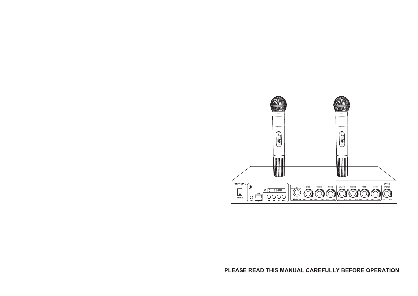
SV-55 PROFESSIONAL MIXER
WITH VHF-302 WIRELESS MICROHONE
AUXUSB
SD
USER’S MANUAL
Page 2
MIXER HANDHELD MIC
Front Panel
USB
AUX
SD
5
1 2
3
4
678 9
10
11 12
13
15 161718 19 2 0
14
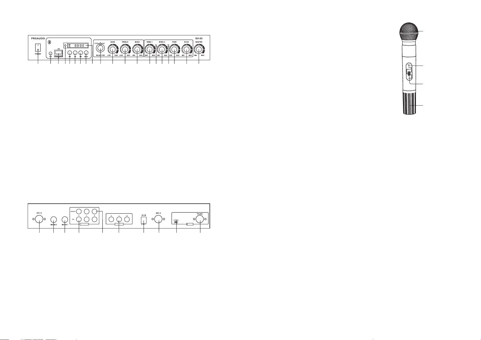
1. Power: Press to turn on/off the unit.
2. AUX: To be connected with mobile phone, Ta ble t or an oth er ex ter nal a udi o sou rce .
3. USB/TF port: Enables playing audio from USB (DOK) or SD (TF) cards, this is the
"PLAYER".
4. PLAYER IR Remote Sensor.
5. PLAYER previous track.
6. PLAYER Play / Pause.
7. PLAYER next track.
8. PLAYER MODE : Choose input of Player in between USB, SD, AUX or Bluetooth.
9. PLAYER LED Display.
10. Selector: Turn to choose Mp3 player, TV or DVD input.
11. Bass control: Turn to adjust bass of music.
12. Treble control: Turn to adjust treble of music.
13. Volume control of music
14. Volume control of wireless microphone/MIC in 1
15. RF1: Light green when wireless microphone 1 is powered on.
16. Volume control of wireless microphone/MIC in 2
17. RF2: Light green when wireless microphone 2 is powered on.
18. TONE : Turn t o adj ust t one o f mic rop hon e.
19. ECHO: Turn to adjust echo level.
20. Master volume control
Rear Panel
INPUT
21 22 23 26 27 28 29 3024 25
TXOUTPUT
21. ANT B: Antenna of wireless microphone 2.
22. MIC IN 2: To connect wired dynamic MIC.
23. MIC IN 1: To connect wired dynamic MIC.
24. DVD Input: To be connected to DVD , Streamer, Computer or any other Audio or
A/V source.
25. Cable/TV Input: To be connected to Cable TV ou tpu t or an y oth er Aud io or A/ V sou rce .
26. OUTPUT: To be connected to Active Speakers, Hi Fi system, T V or Sc ree ns fo r the
Video out.
27. DC IN: Connect DC end of supplied power adapter here. Connect AC end of power
adapter into a suitable mains power socket.
28. ANT A: Antenna of wireless microphone 1.
29. Channel Switch: Selects one of 3 channels of Wireless Headphones (To buy
separately). Any quantity of Headphones can be operated in 2 different frequencies
at same site.
30. Antenna for DA-601 Headphones.
1. Unscrew the battery cover at the end of the microphone.
Install the provided two 1.5V AA batteries and then close
the cover. Make sure to connect with the correct polarity.
2. Slide power switch to ON position, power LED indicator
should flash once briefly indicating that the transmitter
has sufficient power. If the power LED indicator stays on
or does not light at all, it indicates that the battery has
insufficient power or dead. Please replace new battery.
3. Slide the power switch to MUTE position to mute the
sound.
4. If the microphone is not going to be used for a long
period of time, please slide the power switch to OFF
position and remove the battery from microphone.
SPECIFI CATIONS
A. Overall System
Oscillation Mode: Quartz Controlled
Carrier Frequency Range: Fixed permitted
Frequency Stability: 30ppm
Modulation Mode: F3E
Maximum Deviation: +/-35Khz
Audio Dynamic Range: >100dB
S/N: >100dB
Frequency Response: 80~20000Hz at ±3dB
T.H.D: <0.5%
Operating Distance: 30M
Operating Temperature: -20℃~5 0℃
B. Receiver
Mirror Image Rejection: >50dB
De-emphasis: 50μs
LINE input sensitivity: 380mV/-8.5dB
MIC input sensitivity: 5mV/-46dB
LINE input impedance: 10KΩ
MIC input impedance: 8KΩ
Power Supply: DC18V/500mA
Power Dissipation: <800mW
C. Microphone
Mike Capsule: dynamic
Pre-emphasis: 50μs
Antenna: Built-in housing
RF Output: <10mW
Spurious Emission: >40dB
Power Supply: 2x 1.5V AA batteries
Power Dissipation: <250mW
Gri lle
(Capsule inside)
Power/low battery
indicator
Power on/off/
mute switch
Battery c over /
Compartment
 Loading...