

Page 1
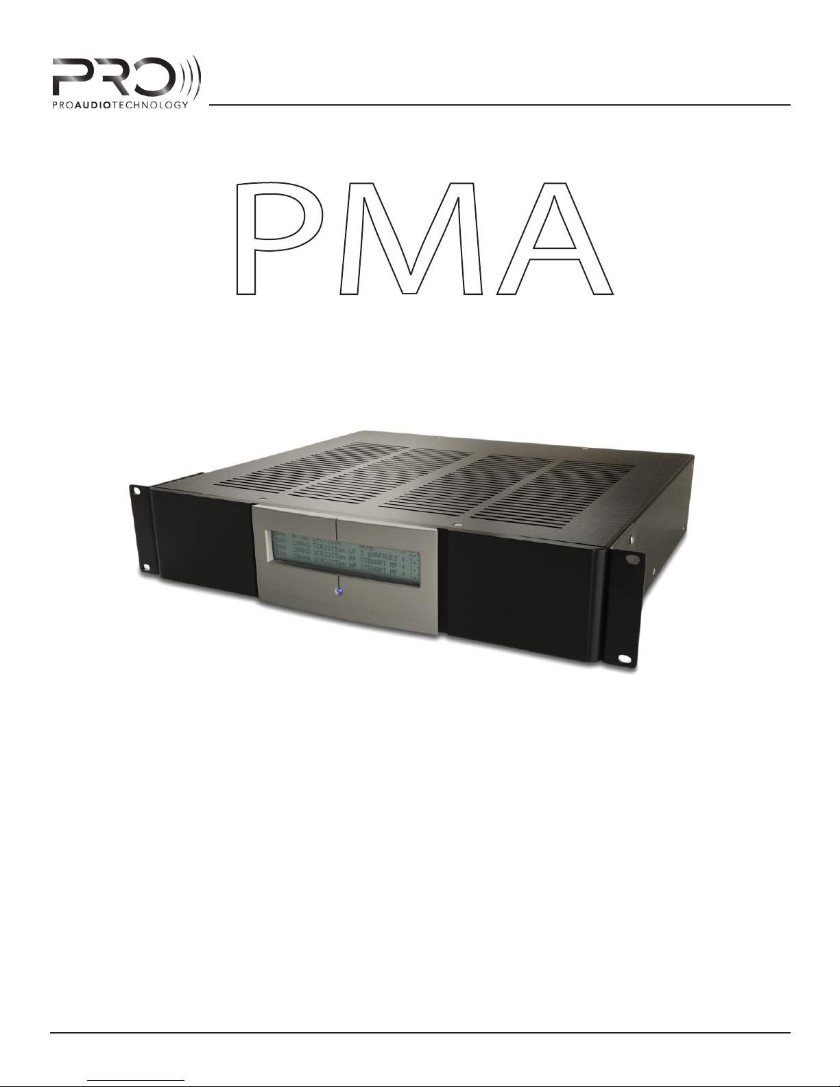
PROGRAMMABLE MODULAR
AMPLIFIER
PMA AMPLIFIER SERIES
PROGRAMMING GUIDE
PMA Installation Guide Rev A
INSTALLATION AND
PMA-2222
PMA-4242
PMA-4444
PMA-9900
PMA-9922
PMA-9942
PMA-9944
PMA-9999
1
Page 2

PMA AMPLIFIER SERIES
CONTENTS
IMPORTANT SAFETY INSTRUCTIONS 4
WELCOME 5
MODEL NUMBERS 5
POWER APPLICATIONS 5
RACK MOUNTING 6
HARDWARE FEATURES: 7
FRONT PANEL 7
1 - LCD DISPLAY 7
2 - POWER LED 9
REAR PANEL 10
1 - POWER AND STATUS AREA 11
2 - PROGRAMMING AND CONTORL AREA 12
3 - INPUT/OUTPUT AREA 13
SOFTWARE FEATURES 15
PMA MANAGER MAIN SCREEN 16
1 - TITLE BAR 16
2 - MAIN MENU 17
3 - INFORMATION PANE 18
4 - DSP CONTROL PANEL 19
5 - UPDATE AMPLIFIER MEMORY BUTTON 22
6 - STATUS BAR 22
COMPENSATION FILTERS 23
SCREEN COMPENSATION 23
CLOTH COMPENSATION 24
ROOM BOUNDARY COMPENSATION 24
HIGH AND LOW PASS FILTERS 26
AMPLIFIER HOOKUP EXAMPLES 27
TWO-WAY BI-AMP “CENTER CHANNEL” HOOKUP EXAMPLE 27
THREE-WAY TRI-AMP “CENTER CHANNEL” HOOKUP EXAMPLE 28
DUAL SUB / BI-AMP CENTER CHANNEL HOOKUP EXAMPLE 28
2
Page 3

PMA AMPLIFIER SERIES
AMPLIFIER PROGRAMMING 29
PROGRAMMING OVERVIEW 29
CONCEPTS TO KNOW 30
PROGRAMMING STEPS 32
STEP 1 : MAKE A PLAN 32
STEP 2 : CONNECT AMPLIFIER TO COMPUTER 32
STEP 3 : POWER ON AMPLIFIER 32
STEP 4 : RUN PMA MANAGER SOFTWARE 33
STEP 5 : SET DSP PARAMETERS FOR EACH AMPLIFER CHANNEL 34
STEP 6 : STORE DSP PARAMETERS IN AMPLIFIER MEMORY 36
TROUBLESHOOTING 37
SPECIFICATIONS 40
WARRANTY 41
Professional Home Cinema, LLC 3-Year Limited Warranty 41
CONTACTING PROFESSIONAL HOME CINEMA, LLC 41
3
Page 4
PMA AMPLIFIER SERIES
IMPORTANT SAFETY INSTRUCTIONS
1. Read all instructions.
2. Keep these instructions.
3. Heed all warnings.
4. Follow all instructions.
5. Do not use this apparatus near water.
6. To prevent re or shock, do not expose this equipment to moisture or water.
7. Clean only with a dry cloth.
8. Do not block any ventilation openings. Install in accordance with manufacturer’s instructions.
9. Do not install near any heat sources such as radiators, heat registers, stoves or other apparatus (including other rack
equipment) that produce heat.
10. Do not defeat the safety purpose of the grounding -type plug. A grounding plug has two blades and a grounding
prong. The wide blade and third prong are provided for your safety. If the provided plug does not t your outlet, consult an electrician for the replacement of the obsolete outlet.
11. Protect power cord from being walked on or pinched, particularly at plugs, convenience receptacles, and point where
they exit the apparatus.
12. Use only attachements/accessories specied by Professional Home Cinema, LLC.
13. Use only with hardware, brackets, stands, and components sold with the apparatus or supplied by Professional Home
Cinema, LLC
14. Unplug the apparatus during lightning storms or when unused for long periods of time.
15. Refer all servicing to qualied service personel. Servicing is required when the apparatus is damaged in any way, such
as power supply cord or plug is damaged, liquid has been spilled or objects have fallen into the apparatus, the apparatus has been exposed to rain or moisture, does not operate normally or has been dropped.
16. To completely disconnect this apparatus from the AC Mains, disconnect the power supply cord from the AC receptacle.
17. The mains plug of the power supply cord shall remain readily operable.
The lightning ash with arrowhead symbol with equilateral triangle
is intended to alert the user to the presence of uninsulated “dangerous voltage” within the product’s enclosure that may be of sucient
magnitude to constitute a risk of electric shock to persons.
The exclamation point within an equilateral triangle is intended to
alert the user to the presence of important operating and mainte-
!
nance (servicing) instructions in the literature accompanying the
product.
CAUTION: TO REDUCE THE RISK ELECTRIC SHOCK, DO NOT REMOVE
THE COVER, NO USER-SERVICEABLE PARTS INSIDE. REFER SERVICING TO QUALIFIED PERSONEL.
WARNING: TO PREVENT FIRE OR ELECTIC SHOCK, DO NOT EXPOSE
EQUIPMENT TO RAIN OR MOISTURE.
© COPTYRIGHT 2011, PROFESSIONAL HOME CINEMA., LLC
4
Page 5

PMA AMPLIFIER SERIES
WELCOME
The PMA series ampliers represent the second generation ampliers from Pro Audio Technology
and were developed with a single primary goal: to make installing, conguring and optimizing your
PRO audio system straight forward and as painless as possible.
MODEL NUMBERS
The model number of your PMA amplier designates the installed amplier power. The numeral
in the rst (left-most) position indicate the power in Channel 1, the second numeral indicates the
power installed in Channel 2, and so on.
Model numerals:
'2' = 200W
'4' = 450W
'9' = 1000W
'0' = No power installed
Model number sux:
'T' = Indicates optional input transformers are installed
Example: PMA-9942T has 1000W installed in Channels 1 and 2, 450W installed in Channel 3 and
200W installed in Channel 4 and has optional input isolation transformers installed.
POWER APPLICATIONS
As a general rule, each of the three power levels is intended to drive certain loudspeaker drivers or
systems within the home cinema or distributed audio application.
Bi or Tri-Amplied Large Format Full Range Systems (i.e. SCR-2215sm):
LF Driver : 450W or 1000W
MF Driver : 450W
HF Driver : 450W
Bi-Amplied Medium Format Full Range Systems (i.e. SCR-12sm):
LF Driver(s) : 450W
HF Driver : 200W
Passive or Bi-Amp Small Format and Architectural Full Range Systems (i.e. iw models):
Bi-amp LF Driver : 200W
Bi-amp HF Driver : 200W
Passive Mode : 200W
Subwoofers:
Small Format Architectural Subwoofers : 200W
Medium Format Subwoofers : 450W
Large Format Subwoofers : 1000W
5
Page 6
PMA AMPLIFIER SERIES
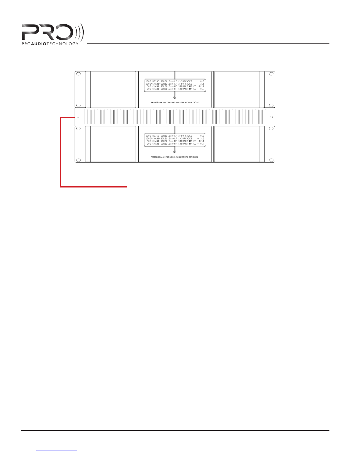
PLACE A 1U SPACER BETWEEN AMPLIFIERS AND
OTHER COMPONENTS IN THE RACK
PMA AMPLIFIERS WITH 1U RACK SPACER
RACK MOUNTING
The PMA series ampliers ship from the factory with rack mount ears installed and are ready to be
placed into any industry-standard 19” equipment rack. The PMA chassis is 2U high.
To keep the equipment and listening rooms as quiet as possible, the PMA ampliers do not have
cooling fans and therefore rely on convection to remove waste heat from the chassis. The good
news is, however, that the PMA ampliers are extremely ecient (> 80% eciency). Still, with EIGHT
HUNDRED to FOUR THOUSAND WATTS per chassis, even with 80% eciency they do generate a
modest amount of heat, especially at idle. (Refer to the SPECIFICATIONS section for more information).
For this reason, it is recommended that you place a 1U spacer between the PMA amplier chassis
and any neighboring equipment, including other PMA ampliers, to insure adequate ventilation.
During normal operation, the front panels of the PMA ampliers will become warm to the touch, but
will not become hot.
To further minimize heat generated at idle, it is recommended that you take advantage of the
STANDBY feature of the amplier, and place the amps into STANDBY whenever not in use. This will
keep power consumption and therefore waste heat to a minimum.
RACK MOUNTING
6
Page 7
HARDWARE FEATURES:
2 - POWER LED
PMA AMPLIFIER SERIES
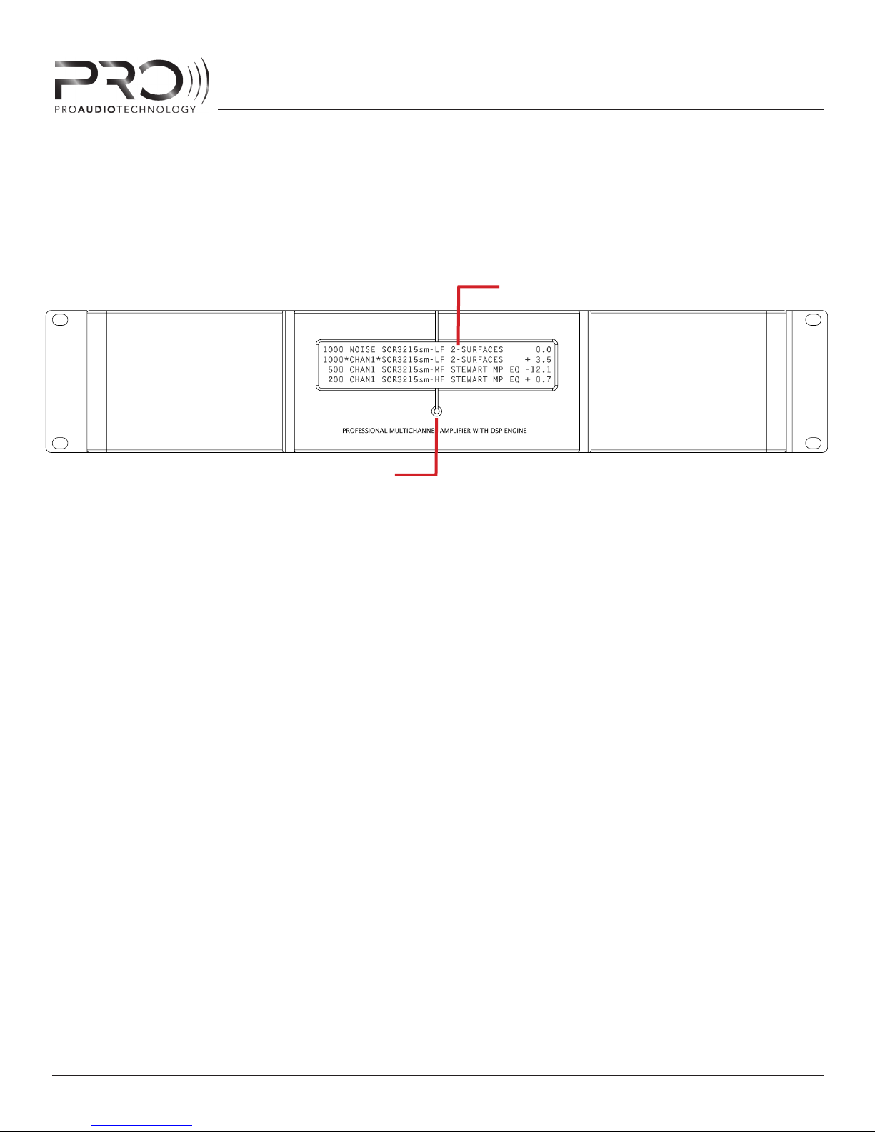
1 - LCD DISPLAY
PMA FRONT PANEL
FRONT PANEL
1 - LCD DISPLAY
The display will illuminate and text will appear when the amplier main power is turned on. At start
up, the display will temporarily display the amp model and serial number along with rmware version currently installed in the amplier. Once the amplier has completed its initialization process,
the display will show details about the amplier conguration and programming.
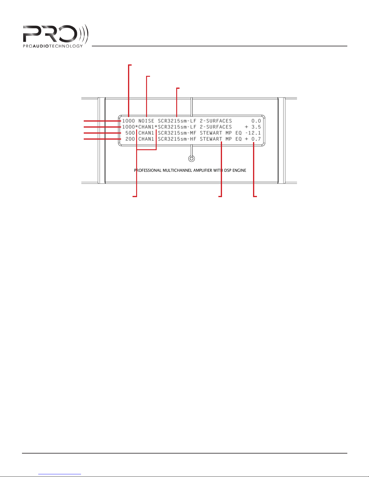
The text on each row of the display corresponds to an amplier channel. The top row, Row 1, corresponds to Channel 1 of the amplier. All data shown on this row applies only to Channel 1. Rows 2
through 4 correspond to Channels 2 through 4, respectively.
Each column of the LCD display indicates an important parameter of the amplier status and/or amplier programming. Column headings have intentionally been omitted from the chassis front panel
to preserve a clean appearance. Please review the descriptions below to learn what information is
shown in each column. After reviewing the information, deciphering the displayed text will be easy
and intuitive.
When the amp is placed into STANDBY mode, the display backlight will dim but the text will still be
visible.
HARDWARE FEATURES - FRONT PANEL
7
Page 8
CHANNEL 1
CHANNEL 2
CHANNEL 3
CHANNEL 4
PMA AMPLIFIER SERIES
1.1 - INSTALLED POWER
1.3 - SIGNAL ROUTING
1.4 - SPEAKER PROGRAM
1.2 - CHANNEL MODIFIED
INDICATORS
1.5 - COMPENSATION
FILTER
1.6 - CHANNEL GAIN
LCD DISPLAY
1.1 - INSTALLED POWER
The rst display column indicates the installed amplier power in Watts into 4-ohms. Most PRO
LF drivers are 4-ohm nominal impedance, so this number is an accurate description of power
available. If no power module is installed, this column will read “NONE”.
1.2 - CHANNEL MODIFIED INDICATORS
When a DSP setting has been modifed on a amplier channel but the changes have not yet been
saved to amplier memory, an aesterisk will appear on each side of the Signal Routing column.
Once the current settings have been saved to amplifer memory, the asterisks will disappear. No
asterisks on the front panel display indicates that settings in amp memory are “in-sync” with the
running DSP programming.
1.3 - SIGNAL ROUTING
The second display column indicates the source currently routed to the amplier channel (as set
up in PMA Manager control software, see “Amplier Programming”). The source may be any one
of the four balanced audio input jacks on the amplier back panel, or the channel may be routed
to the internal pink noise generator. If the channel is routed to the internal pink noise generator,
this column will read “NOISE”.
If the channel is currently muted via software control, this column will show “MUTE”. From the
factory, each channel is by default routed to its corresponding balanced audio input jack. That is,
Channel 1 of the amplier is “listening” to Channel 1 balanced audio input. Channel 2 is routed to
the Channel 2 balanced audio input, and so on. Signal routing can easily be changed as required
by the system design via PMA Manger control software.
HARDWARE FEATURES - FRONT PANEL
8
Page 9

PMA AMPLIFIER SERIES
1.4 - SPEAKER PROGRAM
Column three of the display indicates the speaker program that is installed (as set up in PMA
Manager control software, see “Amplier Programming”) for the channel. From the factory, the
amplier is pre-programmed with no speaker program and this column will display “NONE”.
1.5 - COMPENSATION FILTER
The forth column indicates any acoustic compesation lter installed (as set up in PMA Manager
control software, see “Amplier Programming”) for the channel. These customized lters are used
to correct for the acoustic eect of perforated video screens, nearby room boundaries or to apply
high or low pass ltering. From the factory, the amplier is pre-programmed with no compensation lter installed and this column will read “NONE”.
1.6 - CHANNEL GAIN ADJUSTMENT
The fth column indicates the channel gain setting (as set up in PMA Manager control software,
see “Amplier Programming”). Channel gain should only be used in certain circumstances such
as adjusting mulitple subwoofer levels when the preamp processor in the system has only a
single LFE output. From the factory, all channel gains are set to 0.0dB
CAUTION:
All PRO loudspeaker programs have precisely optimized output level that precisely match
the outputs of the drivers within a multi-way speaker system. NEVER ADJUST THE LEVELS
OF INDIVIDUAL DRIVERS WITHIN A MULTI-WAY LOUDSPEAKER SYSTEM RELATIVE TO ONE
ANOTHER.
.
2 - POWER LED
This LED will illuminate when the amplier main power is ON and the amp is not in Standby Mode.
When the amp is OFF, in STANDBY MODE or PROTECT MODE, this LED will be o.
HARDWARE FEATURES - FRONT PANEL
9
Page 10
PMA AMPLIFIER SERIES
ON
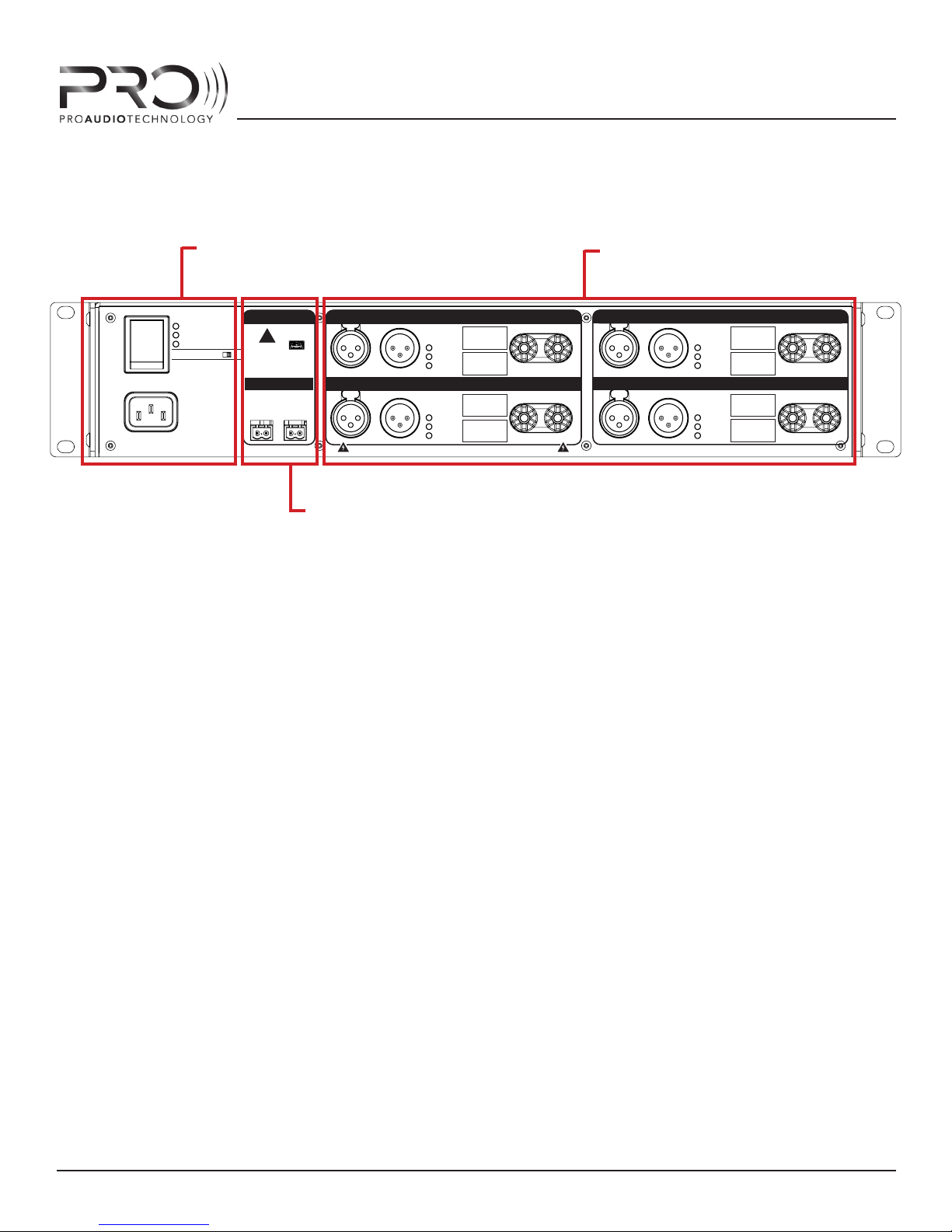
REAR PANEL
1 - POWER AND STATUS INDICATORS
DSP ACTIVITY
STANDBY/PROTECT
POWER
DISPLAY BACKLIGHT
PROGRAM
!
WARNING:
ALL INSTALLED CHANNELS MUST BE
ON
PROGRAMMED WITH CORRECT
LOUDSPEAKER PROGRAM BEFORE
OPERATION. FAILURE TO DO SO WILL
RESULT IN LOUDSPEAKER DAMAGE.
PRO AUDIO TECHNOLOGY “PMA
MANAGER” SOFTWARE REQUIED.
TRIGGER
SHORT OR 0V:
OPEN OR +12V:
INPUT LOOP
+
-
STANDBY
OPERATE
-
USB
+
LOOPINPUT
PROGRAM
CLIP
SIGNAL
LOOPINPUT
PROGRAM
CLIP
WARNING: SHOCK HAZARD. DO NOT OPEN. NO USER-SERVICEABLE PARTS INSID ED ESIGNED AND ASSEMBLED IN HUNTINGT ON BEACH, CA BY PRO AUDIO TECHNOLOGY
SIGNAL
2 - PROGRAMMING AND CONTROL
PMA REAR PANEL
CHANNEL 1
CHANNEL 2
OUTPUT
-
OUTPUT
-
3 - INPUTS AND OUTPUTS
LOOPINPUT
LOOPINPUT
CHANNEL 3
PROGRAM
CLIP
SIGNAL
CHANNEL 4
PROGRAM
CLIP
SIGNAL
+
+
OUTPUT
-
OUTPUT
-
+
+
With the expception of the Power LED and LCD display, all other features of the PMA amplers can be
found on the amp rear panel. The layout of the connectors and controls have been carefully designed
to make connecting to and operating the amplier as easy as possible.
In addition to the usual input and output connectors, you will nd a host of LED’s that indicate amp
operation and programming status which oer useful feedback during system setup and debugging.
There are also labels indicating installed power and speaker program for each channel.
To make installation and setup as easy as possible, all information that is available on the front panel
(and in PMA Manager conrtol software), can also be found here.
The panel is divided into three main areas: POWER AND AMP STATUS, PROGRAMMING AND CONTROL
and INPUTS AND OUTPUTS.
We’ll now take a look at the features within each area individually.
HARDWARE FEATURES - REAR PANEL
10
Page 11
PMA AMPLIFIER SERIES
1.2 - STATUS INDICATORS
1.1- MAIN POWER
SWITCH
1.4 - AC INLET
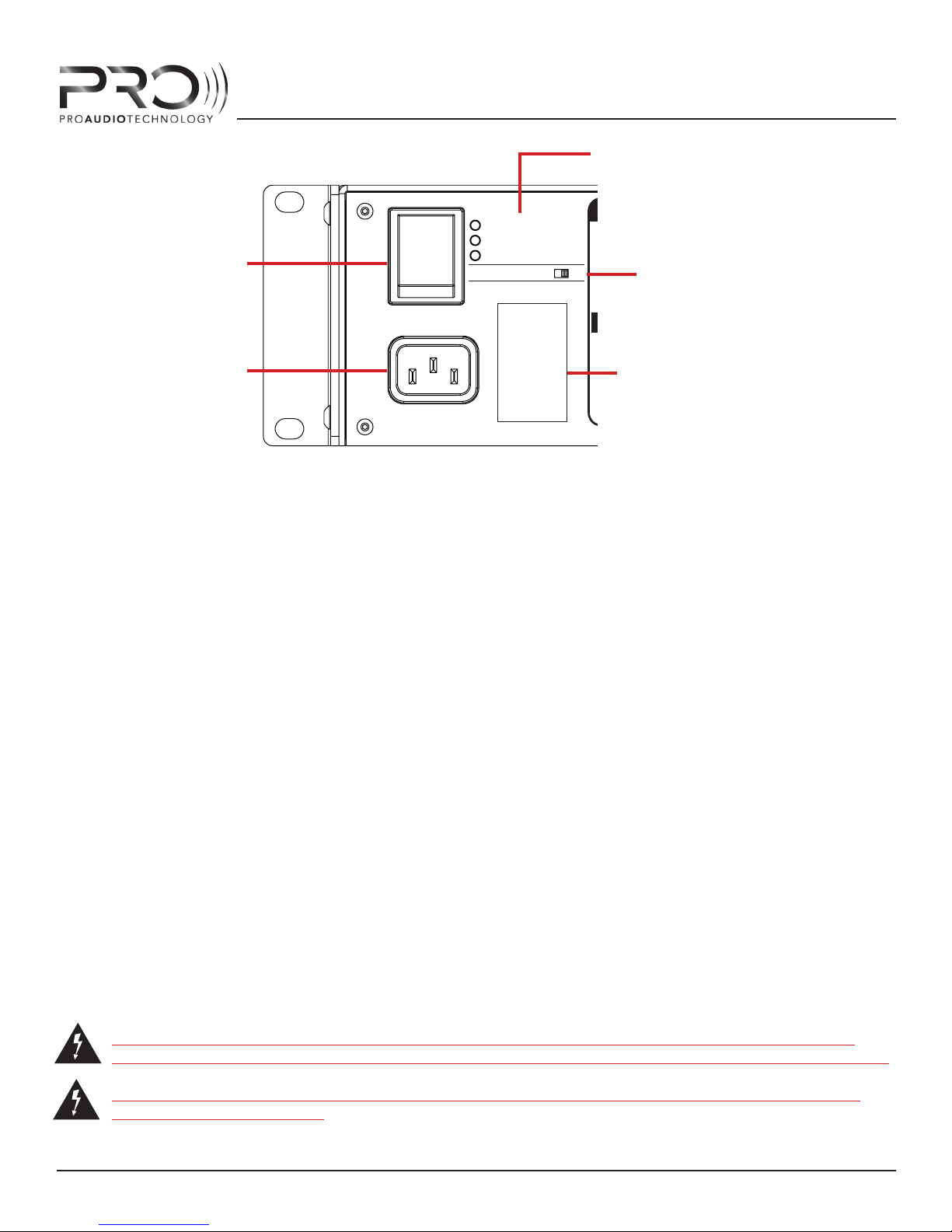
1 - POWER AND STATUS AREA
1.1 - MAIN POWER SWITCH
Press the top of the rocker switch to engage the amplifer main electrical power. Press the bottom
of the rocker switch to disengage the power and turn the amplier o. If using 12VDC or relay
trigger to control amp operation, this switch should be left in the ON position.
ON
DSP ACTIVITY
STANDBY/PROTEC T
POWER
DISPLAY BACKLIGHT
POWER AND STATUS AREA
PROGRAM
!
WARNING:
ALL INSTALLED CHANNELS MUST BE
ON
PROGRAMMED WITH CORRECT
LOUDSPEAKER PROGRAM BEFORE
OPERATION. FAILURE TO DO SO WILL
RESULT IN LOUDSPEAKER DAMAGE.
PRO AUDIO TECHNOLOGY “PMA
MANAGER” SOFTWARE REQUIED.
SHORT OR 0V:
OPEN OR +12V:
1.3 - DISPLAY BACKLIGHT
DEFEAT
TRIGGER
INPUT LOOP
1.5 - SERIAL NUMBER LABEL
+
-
USB
STANDBY
OPERATE
-
LOOPINPUT
LOOPINPUT
+
WARNING: SHOCK HAZARD. DO NO T OPEN. NO USER-SERVICEABLE
CHANNEL
PROGRAM
CLIP
SIGNAL
CHANNEL
PROGRAM
CLIP
SIGNAL
1.2 - AMPLIFIER STATUS INDICATORS
DSP ACTIVITY - This LED will illuminate, solid or blinking, when communicating with the amplier via USB software control.
STANDBY/PROTECT - This LED will illuminate when the amp has been put into standby condition, or when the amp has entered protection mode due to an operational fault.
POWER - This LED will illuminate when the amplier main power is on.
1.3 - FRONT PANEL DISPLAY BACKLIGHT DEFEAT
Use this switch to defeat (turn-o) the amplier front panel LCD display backlight. It is recommended that once installation is complete, the front panel backlight be turned o with this
switch to conserve power and preserve backlight life. This will defeat the backlight itself, but not
the text displayed. STANDBY and PROTECT modes will still be indicated on the front panel via the
power LED.
1.4 - AC INLET
Main AC power inlet. Connect the mains power cable here.
CAUTION: CONNECT ONLY LINE VOLTAGE INDICATED ON SERIAL NUMBER LABEL. CONNECTING THE AMPLIFIER TO ANY OTHER AC VOLTAGE WILL RESULT IN AMPLIFIER DAMAGE.
WARNING: THIS AMPLIFIER MUST BE CONNECTED TO AN AC OUTLET WITH PROTECTIVE
EARTHING CONNECTION
HARDWARE FEATURES - REAR PANEL
11
Page 12
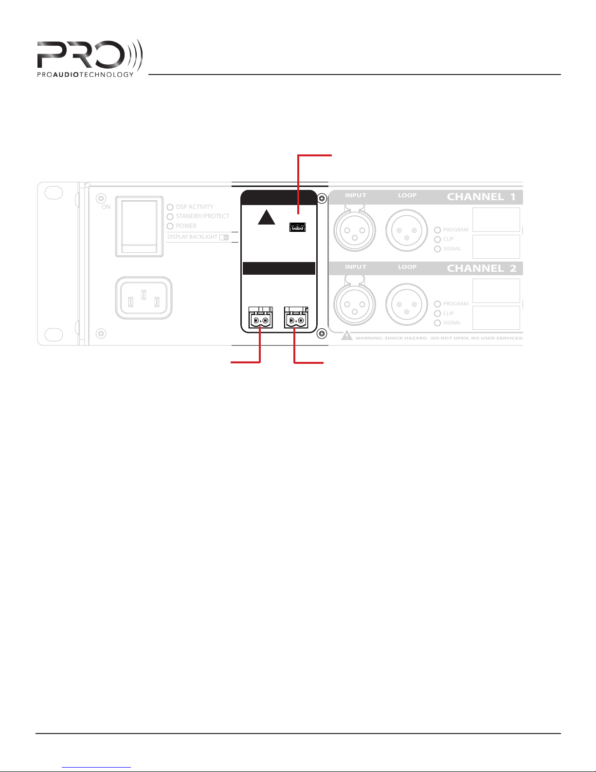
1.5 - AMPLIFIER SERIAL NUMBER LABEL
This label indicates amplier model, serial number and operating voltage.
2.1 - USB PORT
PMA AMPLIFIER SERIES
ON
DSP ACTIVITY
STANDBY/PROTEC T
POWER
DISPLAY BACKLIGHT
ON
2.2 - TRIGGER INPUT
PROGRAMMING AND CONTROL AREA
2 - PROGRAMMING AND CONTORL AREA
2.1 - USB PORT
Connect the PMA amplier to your computer at this port using a mini USB cable. Microsoft Windows XP or Windows 7 will discover the PMA unit and install the required drivers. When doing
this for the rst time, this process may take a few minutes. On subsequent connections, Windows
will install the driver more quickly. Refer to “Amplifer Programming” section of this manual for
more information. Operating systems other than Windows XP and Windows 7 are not supported.
PROGRAM
USB
!
WARNING:
ALL INSTALLED CHANNELS MUST BE
PROGRAMMED WITH CORRECT
LOUDSPEAKER PROGRAM BEFORE
OPERATION. FAILURE TO DO SO WILL
RESULT IN LOUDSPEAKER DAMAGE.
PRO AUDIO TECHNOLOGY “PMA
MANAGER” SOFTWARE REQUIED.
TRIGGER
SHORT OR 0V:
OPEN OR +12V:
INPUT LOOP
-
STANDBY
OPERATE
+
+
-
LOOPINPUT
LOOPINPUT
WARNING: SHOCK HAZARD. DO NO T OPEN. NO USER-SERVICEABLE PARTS INSIDED
CHANNEL 1
PROGRAM
CLIP
SIGNAL
CHANNEL 2
PROGRAM
CLIP
SIGNAL
2.3 - TRIGGER LOOP OUTPUT
OUTPU T
-
OUTPU T
-
+
+
2.2 - 12V/CONTACT CLOSURE TRIGGER INPUT
Connect a 12VDC trigger output, or contact closure relay to this port using the supplied Phoenix
two-position male connector. The STANDBY/OPERATE TRIGGER will operate with applied DC voltage or with an open/short ciruit.
When connecting to a control system relay/contact closure output, program the relay to close
(short) the terminals to engage STANDBY; open the terminals for OPERATE. When connecting to
a DC trigger output, make sure to observe correct voltage polarity. Failure to do so could result in
damage to the PMA input or your component trigger output. 0VDC will engage STANDBY mode;
5VDC up to 12VDC will cause the amp come to out of STANDBY MODE and OPERATE.
3 - 12V/CONTACT CLOSURE LOOPING OUTPUT
Use this port to “loop” the Trigger input signal to another PMA chassis using the supplied Phoenix two-position male connector. When using a DC trigger input, make sure to observe correct
polarity, or component damage may occur.
HARDWARE FEATURES - REAR PANEL
12
Page 13
PMA AMPLIFIER SERIES
3.1 - BALANCED ANALOG
DSP ACTIVITY
STANDBY/PROTEC T
POWER
DISPLAY BACKLIGHT
3.2 - LOOPING OUTPUT
AUDIO INPUT
PROGRAM
USB
!
WARNING:
ALL INSTALLED CHANNELS MUST BE
ON
PROGRAMMED WITH CORRECT
LOUDSPEAKER PROGRAM BEFORE
OPERATION. FAILURE TO DO SO WILL
RESULT IN LOUDSPEAKER DAMAGE.
PRO AUDIO TECHNOLOGY “PMA
MANAGER” SOFTWARE REQUIED.
TRIGGER
SHORT OR 0V:
OPEN OR +12V:
INPUT LOOP
-
STANDBY
OPERATE
+
+
-
3.5 - PROGRAM LABEL LOCATION
3.3 - CHANNEL STATUS INDICATORS
3.4 - CHANNEL POWER LABEL
LOOPINPUT
LOOPINPUT
WARNING: SHOCK HAZARD. DO NO T OPEN. NO USER-SERVICEABLE PARTS INSIDED ESIGNED AND ASSEMBLED IN HUNTINGT
CHANNEL 1
PROGRAM
CLIP
SIGNAL
CHANNEL 2
PROGRAM
CLIP
SIGNAL
OUTPU T
-
OUTPU T
-
+
+
LOOPINPUT
LOOPINPUT
3.6 - SPEAKER OUTPUTS
INPUT/OUTPUT AREA
CHANNEL
PROGRA
CLIP
SIGNAL
CHANNEL
PROGRA
CLIP
SIGNAL
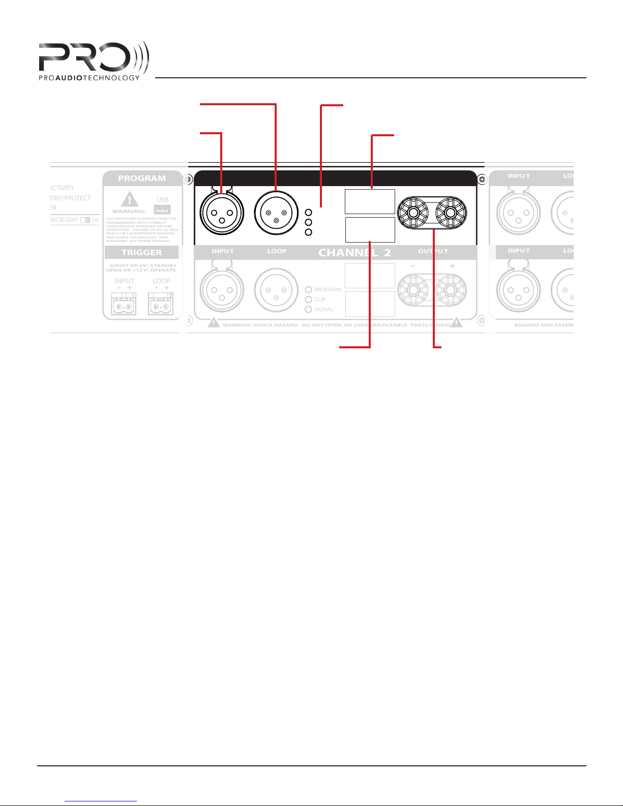
3 - INPUT/OUTPUT AREA
3.1 - BALANCED ANALOG AUDIO XLR INPUT
Connect this balanced analog audio input to the post-processed analog audio output from your
surround sound processor. Pin 1 is ground; Pin 2 is signal +; Pin 3 is signal -. To minimize the risk
of unwanted ground plane noise, use of a balanced preamplifer is highly recommended.
When connecting to unbalanced (single-ended) audio outputs, connect pins 1 (GND) and 3(-) together and then to audio GROUND inside the male XLR jack at the amplier-end of the interconnect cable. Make sure the preamp/processor is grounded. That is, make sure that it has a threeprong grounding AC power cord. If it does not, you will need to connect the preamp chassis to
ground manually. Failure to connect to a properly grounded single-ended processor will likely result
in unwanted ground noise that will enter the system and be heard from the loudspeakers.
3.2 - BALANCED ANALOG AUDIO LOOPING OUTPUT
Use this XLR output to “loop” the analog audio input signal to another PMA chassis. This is useful,
for instance, when there are more than 4 subwoofers within a system and it’s necessary to route
the LFE signal to more than one PMA amplier.
NOTE: Signal input into one of the XLR balanced audio inputs may be routed to any amplier
channel within the same PMA amp via PMA Manager software (refer to “Amplifer Programming”
section of this manual for more information).
HARDWARE FEATURES - REAR PANEL
13
Page 14

3.3 CHANNEL STATUS INDICATORS
PROGRAM (RED)
This LED will illuminate when a valid PRO loudspeaker program has been installed into the
PMA DSP for this channel. If this LED is not illuminated, that means no program is installed
and audio will not pass on this channel.
By default, the PMA amplifer is shipped from the factory with no program installed to prevent
“accidents” during system setup that may cause damage to the loudspeakers in the system.
Every channel of the amplifer must be correctly programmed via PMA MANAGER SOFTWARE
prior to amplier use.
CLIP (YELLOW)
This LED will illuminate when the amplier output maximum has been reached and the builtin clip limiter is engaged. The limiter will prevent clipping from occuring.
SIGNAL (GREEN)
PMA AMPLIFIER SERIES
This LED will illuminate when a moderate input signal is detected at the input and will therefore “blink” in accordance with the strength of the audio content. Under high level signals,
the LED may illuminate constant.
3.4 - CHANNEL POWER LABEL
This label indicates the installed power on this channel and is placed at the factory.
3.5 - CHANNEL PROGRAM LABEL LOCATION
This outlined rectangular area will accept the blank labels provided with the PMA amplifer and
allow you to mark on the amp what program is installed in the channel. Use a perment maker
(i.e. Sharpie) to write the program on the label and ax it at this location. Alternately, use a label
maker to create your own program labels and ax them here.
3.6 - LOUDSPEAKER OUTPUTS
Connect a PRO passive loudspeaker system or bi or tri-amp speaker driver to these binding posts
making sure to observe correct polarity. The posts will accept bare wire or dual banana plugs.
High quality banana plugs are recommended for ease of installation and system maintenance.
CAUTION: THE AMPLIFIER MODULES INSIDE THE PMA AMPLIFIER OPERATE IN BRIDGED
(“BRIDGED TIED LOAD”, OR “BTL”) MODE. AS SUCH, BOTH LOUDPSPEAKER OUTPUT POSTS
!
ARE CONNECTED TO HOT SIGNALS. DO NOT CONNECT ANY SPEAKER OUTPUT POST TO
GROUND, OR AMPLIFIER DAMAGE WILL RESULT.
All connectors and indicators for each of channels 2 thru 4 follow the same layout.
HARDWARE FEATURES - REAR PANEL
14
Page 15
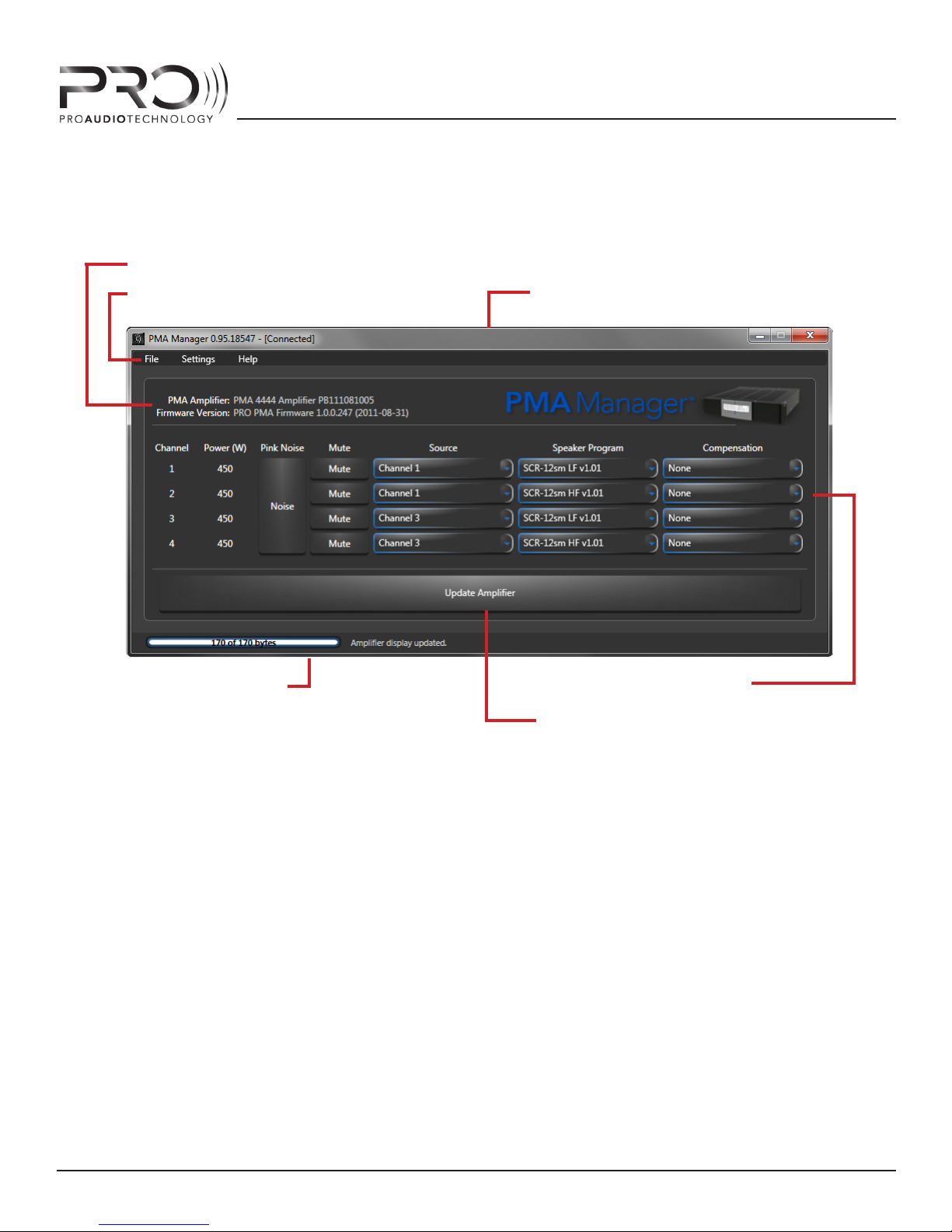
SOFTWARE FEATURES
3 - INFORMATION PANE
PMA AMPLIFIER SERIES
2 - MAIN MENU
6 - STATUS BAR
1 - TITLE BAR
4 - DSP CONTROL PANEL
5- UPDATE MEMORY BUTTON
PMA MANAGER USER INTERFACE
SOFTWARE FEATURES
15
Page 16
PMA AMPLIFIER SERIES
PMA MANAGER MAIN SCREEN
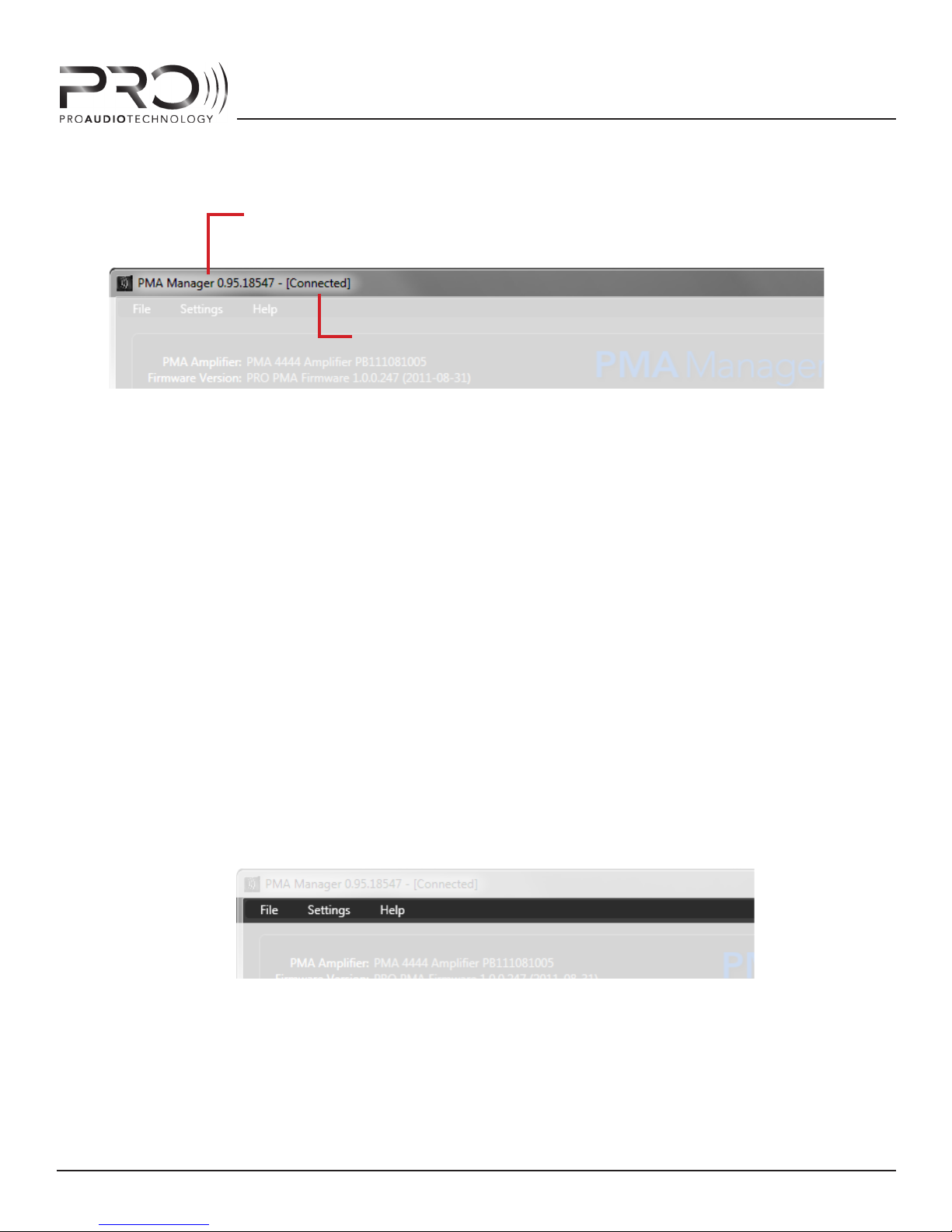
1.1 - PMA SOFTWARE VERSION NUMBER
1.2 - CONNECTION STATUS
PMA MANAGER TITLE BAR
1 - TITLE BAR
In the top-most section of the user interface, known as the “Title Bar”, PMA Manager will display
information about the software and the connection to the amplier hardware.
1.1 PMA MANAGER SOFTWARE VERSION NUMBER
PMA Manager will display the running version of the softare showing the version, revision and
build code. Information about the software can also be found by selecting HELP -> ABOUT from
the main menu.
1.2 CONNECTION STATUS
If a valid connection to a PMA amplier exists, PMA Manager will show “[Connected]” immediately after the software version; if PMA Manager could not establish communication with an amplier, it will display “[Disconnected]” here. If you’re having trouble establishing a connection, refer
to the TROUBLESHOOTING section of this manual.
PMA MANAGER MAIN MENU
SOFTWARE FEATURES
16
Page 17

2 - MAIN MENU
2.1 - FILE
The le menu contains menu commands related to amplier connections and le management.
PMA AMPLIFIER SERIES
2.1.1 Connect
Select this menu item to connect to a new PMA amplier while the software is running
but is not connected to an amplier. A list of available ampliers will appear.
2.1.2 Disconnect
Select this menu item to disconnect from a PMA amplier, for example, when programming a rack full of amps in order to move to the next unprogrammed amp.
2.1.3 Backup
Select Backup to store an archive of all current amp settings to a le on your local hard
disk that can later be recalled. This is useful when you use the same conguration on
many ampliers - you don’t need to manually enter all programs and settings, you can
simply restore the amp “image” from the backup le. This is also useful as a way to
keep record of settings should an amplier need to be replaced in the future.
2.1.4 Restore
2.1.5 Exit
2.2 - SETTINGS
The Settings menu contains commands related to software features and layout of the GUI.
2.2.1 - Enable Advanced Controls
2.2.2 - View Command Window
Choose Restore to load all amplier settings from a previously made Backup le located on your hard disk. This command will display all control settings in PMA Manager,
load them into the DSP, and store them in amplier memory.
Select Exit to disconnect from the PMA amplier and close PMA Manager Sotware.
Select Enable Advanced Controls to gain access to advanced DSP controls such as
channel level adjustment and low frequency paramtric EQ lters.
Selecting this option will expand the software GUI to display a scrolling list of recent
commands executed by the software. PRO technical support engineers use this feature to decipher the operation of the software should a problem be encountered. It is
not needed during normal use.
SOFTWARE FEATURES
17
Page 18
2.3 - HELP
PMA AMPLIFIER SERIES
The Help menu contains commands related to user help and information.
2.3.1 User Manual
Selecting this option will load and display this manual in PDF format on your computer
screen for reference while running the software.
2.3.2 Technical Support
Brings up a form with information about how contact PRO Technical Support engineers.
2.3.3 About
Will display information about PMA Manager software.
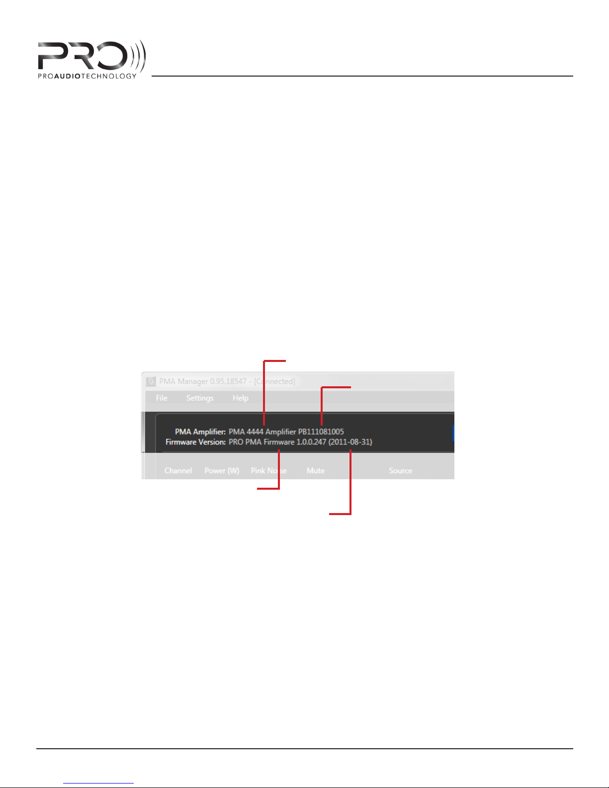
3.1 - PMA AMPLIFIER MODEL
3.2 - PMA AMPLIFIER SERIAL NUMBER
3.3 - AMPLIFIER FIRMWARE VERSION
3.4 - AMPLIFIER FIRMWARE DATE
PMA MANAGER INFORMATION PANE
3 - INFORMATION PANE
The Information Pane displays information about the currently-connected PMA Amplier hardware.
3.1 - PMA Amplier Model
3.2 - PMA Amplier Serial Number
3.3 - PMA Amplier Firware Version
3.4 - PMA Amplier Firmware Date
SOFTWARE FEATURES
18
Page 19
PMA AMPLIFIER SERIES
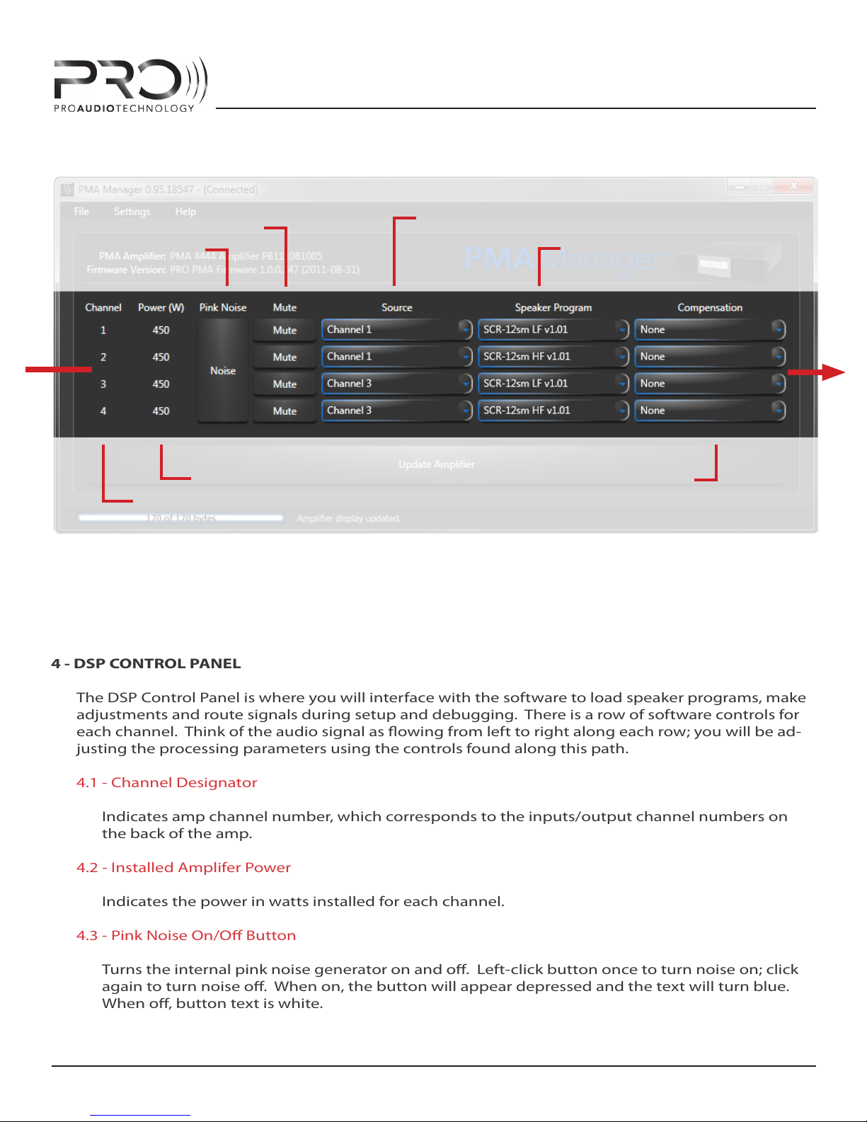
4 - DSP CONTROL PANEL
The DSP Control Panel is where you will interface with the software to load speaker programs, make
adjustments and route signals during setup and debugging. There is a row of software controls for
each channel. Think of the audio signal as owing from left to right along each row; you will be ad-
justing the processing parameters using the controls found along this path.
4.1 - Channel Designator
Indicates amp channel number, which corresponds to the inputs/output channel numbers on
the back of the amp.
4.2 - Installed Amplifer Power
Indicates the power in watts installed for each channel.
4.3 - Pink Noise On/O Button
Turns the internal pink noise generator on and o. Left-click button once to turn noise on; click
again to turn noise o. When on, the button will appear depressed and the text will turn blue.
When o, button text is white.
4.4 - MUTE ON/OFF BUTTONS
4.3 - PINK NOISE
ON/OFF BUTTON
4.2 - INSTALLED POWER 4.7 - COMPENSATION FILTER DROP
4.1 - CHANNEL DESIGNATOR
4.5 - ROUTING DROP DOWN LIST CONTROL
4.6 - SPEAKER PROGRAM DROP
DOWN LIST CONTROL
DOWN LIST CONTROL
PMA MANAGER DSP CONTROL PANEL
19
SOFTWARE FEATURES
Page 20

PMA AMPLIFIER SERIES
4.4 - Mute On/O Buttons
Mutes the selected channel. Left-click the button once to engage mute; left-click again to unmute. When muted, the button will appear depressed and the text will turn blue. When un-muted, button text is white.
4.5 - Channel Routing Drop Down List Controls
This drop-down list control allows amp channels to be routed to any one of ve possible “sources”: Channels 1-4 analog audio XLR inputs (on amplier rear panel), or to the inernal pink noise
generator.
To select a source, left-click on the down arrow at the right edge of the control and a list of these
sources will appear. To select a souce from the list, left-click on the source name. The input
signal for that channel will then be routed to the source selected and the name of the source will
appear in the drop-down control.
4.6 - Channel Loudspeaker Program Drop Down List Controls
This drop down list control allows you to install the loudspeaker-specic DSP programs required
to operate all Pro Audio Technology loudspeaker systems. This includes both multi-amp (bi and
tri-amp) as well as passive crossover models.
To load a loudspeaker program, left-click on the down arrow at the right edge of the control and
a list of all available programs will appear. To select a program from the list, left-click on the program name, which will include the loudspeaker model number and inidicate if the program is for
the woofer (“LF”), midrange (“MF”), tweeter (“HF”) or for a passive model (“-P”). The loudspeaker
program will then be loaded into the DSP chip for that channel and the name of the program will
appear in the drop-down control. Subwoofer programs will simply show the subwoofer name.
4.7 - Channel Compensation Filter Drop Down List Controls
This drop down list control allows you to install specially-designed lters to compensate for the
acoustic eect of listening room materials and loudspeaker positons. There are also high and
low pass lters for combining subwoofers and satellite speakers in distributed audio applications.
Please refer to “COMPENSATION FILTERS” section of this manual for more information.
To load a compensation lter, left-click on the down arrow at the right edge of the control and
a list of all available lters will appear. To select a lter from the list, left-click on the lter name,
which will be a description of the lters function (i.e. “80Hz High Pass”), describe a speaker position (i.e. “2-surfaces”) or will be the model of a commercially available perforated video screen
or acoustic cloth (i.e. “Stuart Microperf”). The lter will then be loaded into the DSP chip for that
channel and the name of the lter will appear in the drop-down control.
SOFTWARE FEATURES
20
Page 21
PMA AMPLIFIER SERIES
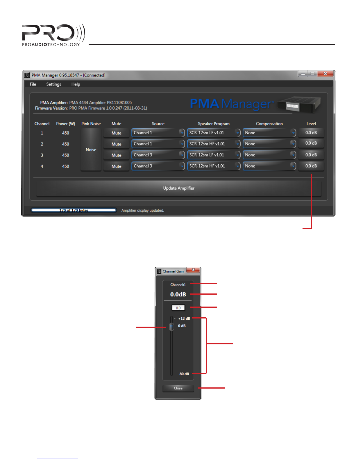
4.8 - CHANNEL LEVEL CONTROLS
PMA MANAGER GUI WITH ADVANCED CONTROLS ENABLED
CHANNEL DESIGNATOR
LEVEL READOUT
TEXT ENTRY FIELD
SLIDE CONTROL
RANGE
CLOSE FORM BUTTON
PMA MANAGER VOLUME CONTROL FORM
SOFTWARE FEATURES
21
Page 22

PMA AMPLIFIER SERIES
4.8 - Channel Level Controls (only visible when “Advanced Controls” are activated).
To adjust the gain of an amp channel left-click on the button under the Level heading in the GUI.
This will open up a new window, or form, with a volume slider and text entry eld. To execute
an adjustment, left-click-and-hold on the slider (virtual sliding volume control) and drag up or
down to the desired setting. The exact value of the adjustment will appear in the text box above
the slider. Once the target value is reached, release the left mouse button and PMA Manager
software will load the setting into the amp DSP and display the setting in large text on the level
readout. Note that the change does not take place until you release the moust button.
For precise adjustments, it may be easier to type the desired gain setting directly into the text
box on the gain form. To do this, left-click and drag to highlight ALL the text in the text eld,
then release the left mouse button and type in your desired setting. Hit ENTER (RETURN) and
PMA Manager will update the text box, slider and readout, then will load the setting into the DSP.
NOTE: You must hit the ENTER or RETURN key after typing in the text box to execute the change.
Once the desired setting has been entered and conrmed, close the gain slider control by leftclicking on the CLOSE button at the bottom of the form.
NOTE: The level setting form is modal, that is it will be on top of the main PMA Manager GUI and will
stay there preventing you from working with the main form until you close it by selecting the CLOSE
button.
5 - UPDATE AMPLIFIER MEMORY BUTTON
Once all the settings and programs are correct, use this button to store all the settings, lters and
programs shown in the GUI (and which are therefore running in the DSP) in the on-board amplier
memory. This will insure that the amp “remembers” the programming when it is powered o and
then powered on again. This will make the programming persistent during amp power cycles. Failure to
execute this step will cause the amplier to boot with the last-saved settings.
To store the settings, left-click on the large “Update Amplier Memory” button. PMA Manager will
write all the current settings to the non-volatile amplier memory. A progress bar will display while
this is taking place. PMA Manager is writing a lot of data at this point and the process will take a
mintue or two.
Once all parameters have been written, the progress bar and the Update Amplifer Memory button
will disappear from the GUI, indicating that the amp memory now corresponds to the running DSP
parameters which are shown on the GUI and on the front panel display. The “Channel Modied”
asterisks will disappear from the display. Everyting at this point, is “in-sync”.
6 - STATUS BAR
When PMA Manager is writing parameters to amplier DSP chip or to amplier memory, the status
bar will update and amplier commands will display to the right of the progress bar.
During complex writes, such as loading a speaker program or updating the amp memory, another
status bar will appear on top of the main PMA Manager form indicating overall progress.
SOFTWARE FEATURES
22
Page 23

PMA AMPLIFIER SERIES
COMPENSATION FILTERS
One of the most inspired features of the PMA Ampliers is the inclusion of no-nonsense DSP tools
that make easy the adjustment of the audio signal to neutralize the eect of listening room conditions that directly impact the acoustic response of the speaker systems.
For clarity, these features address those aspects of the listening room materials and loudspeaker
positions which alter the direct sound of the PRO loudspeaker system. These features do not in
any way fall within the category of so-called “room correction” or “room tuning” paradigms,
which, in our opinion, are not only mis-named, but are also misguided in their objectives*.
The PMA Compensation lters compensate for the acoustic response changes resulting from screen
and listening room fabrics that come between the loudspeaker and the listeners ears and therefore
alter the direct response (direct path from speaker to listener, free from any reections) of the
loudspeaker. There are also lters to neutralize the eect of placing a speaker very close to the
room corners as doing so causes the “space” into which the speaker radiates to be bisected thereby
directing more of the low frequency information into what we would call the “direct sound”.** The
included lters compensate for such “loading” by removing the energy that would normally not be
forced by the room surfaces into the direct response.
These specialized lters have been designed by Pro Audio Technology using a thoughtful combination of laboratory measurements and sophisticated computer models to accurately equalize for
each of the conditions below. You, the installer are not required to have knowledge of engineering
or acoustics, just a knowledge of the listening room materials and loudspeaker locations.
Also included are high and low pass lters to facilitate the combination of subwoofers with satellite
full-range speakers in music and distributed audio applications.
SCREEN COMPENSATION
The screen compensation lters within PMA Manager neutralize the high-frequency roll-o created
by perforated or woven video screens.
You do not need to know the acoustic respsonse of your screen’s material - we’ve taken care of that
for you. All lters were developed by measuring, in a laboratory, the actual acoustic response of
the most popular screen brands.
* For more information about so-called “room tuning” or “room correction” and the perils thereof, take the PRO Training Program as the subject is
addressed in painful detail!
** When the speaker is placed very near a neighboring room wall, the low frequencies, whose wavelengths are very long (5’-50’), are forced into
the room toward the listener without what we would normally dene as a “reection” occurring. The energy does indeed “bounce” o the neighboring wall, but it does so so early in time and with such neglible attenutation that when the “bounce” arrives at the listeners ears, it is for all practical purposes at the same level and in-phase with the sound radiated directly from the speaker to the listeners ears. Our ears integrate this energy
into one sound. Furthermore, this happens uniformly throughout the listening area, which is not true for reected sound that is delayed in time
suciently as to create sucient enough attentionation and phase shift to create an “interference pattern”. The condition we are addressing is the
low frquency gain created by the bisection of the acoustic space at low frequencies.
COMPENSATION FILTERS
23
Page 24

PMA AMPLIFIER SERIES
Each lter is named for the brand and material for which it is designed. Simply pick the lter that
matches the material of your screen and PMA Manager will install a lter which will bring the PRO
speaker response back to the factory standard.
NOTE: For bi-amp systems, this lter needs to be loaded only into the tweeter channel as the eect occurs
only in the high frequencies, well above the band covered by woofers. For tri-amp systems, apply the tler
to both the midrange and tweeter channels. For passive systems, obviously, you must apply the lter to
the amp channel driving the full-range system.
CLOTH COMPENSATION
The cloth compensation lters perform the exact same function as the screen compensation lters
but are designed to address the more modest HF roll-o created by generic fabrics used to cover
loudspeakers which are not behind the video screen itself.
There are three lters each of which address a dierent degree of high-frequency attenuation: low,
medium, and high.
Low Attention should be applied to speakers placed behind relatively “open” weave fabrics. High Attenuation lter is designed to address tightly-woven and thicker fabrics that would have a more aggressive eect on the high frequency response. Medium Attenuation is available for fabrics whose
physical properities fall between the two.
You will probably need to experiment a bit to determine which of the three lters best neutralizes
the eect of your fabric. The goal is to achieve natural, open, high-frequency response from the
speaker without causing the sound to become too “bright”.
NOTE: For bi-amp systems, this lter needs to be loaded only into the tweeter channel as the eect occurs
only in the high frequencies, well above the band covered by woofers. For tri-amp systems, apply the tler
to both the midrange and tweeter channels. For passive systems, obviously, you must apply the lter to
the amp channel driving the full-range system.
ROOM BOUNDARY COMPENSATION
The room boundary lters are designed to compensate for the eect of placing a speaker very
close to the room corners (front wall-side wall, front wall-oor, front wall-side wall-oor) as doing so
causes the “space” into which the speaker radiates to be bisected thereby directing more of the low
frequency information into what we would call the “direct sound”.* The included lters compensate
for such “loading” by removing the energy that would not normally be forced by the room surfaces
into the direct response.
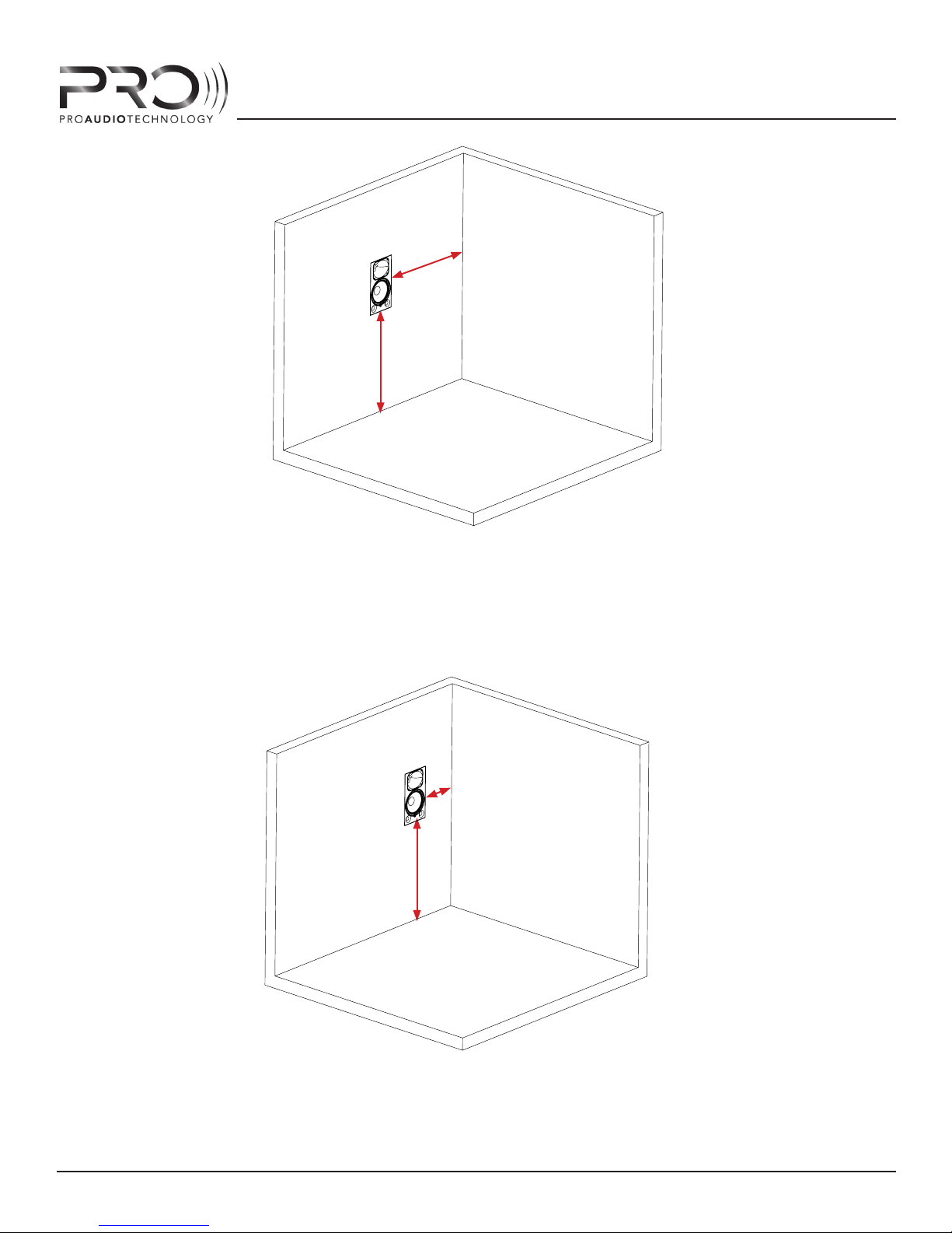
PRO loudspeakers are designed to be mounted into a wall surface with the neighboring surfaces
(adjacent room walls, oor, ceiling) sucently far enough away as to not materially eect low frequency reponse. We’ll refer to this condition as “1 surface loading”. It is also sometimes referred to as
“2pi loading”. Please refer to the illustration on the following page.
COMPENSATION FILTERS
24
Page 25
PMA AMPLIFIER SERIES
D
side
1 SURFACE LOADING
In this case, the speaker is sufciently far away enough (4’ or
greater) from room side wall and
D
oor
oor to be considered “1 Surface”
loading.
D
= 4’ min
side
D
= 4’ min
oor
“1 SURFACE” - NO COMPENSATION NECESSARY
When the speaker is placed closer than approximately 4’ to an adjacent surface (i.e. side wall or oor)
the low frequencies will be boosted. PMA Manager oers lters to compensate for this eect based
upon the approximate distance to the adjacent surface.
D
side
D
oor
2 SURFACE LOADING
In this case, the speaker is close
to one adjacent surface.
D
= 0’ - 4’
side
D
= 4’ min
oor
2 SURFACE LOADING - USE “2-SURFACES” FILTER
COMPENSATION FILTERS
25
Page 26
PMA AMPLIFIER SERIES
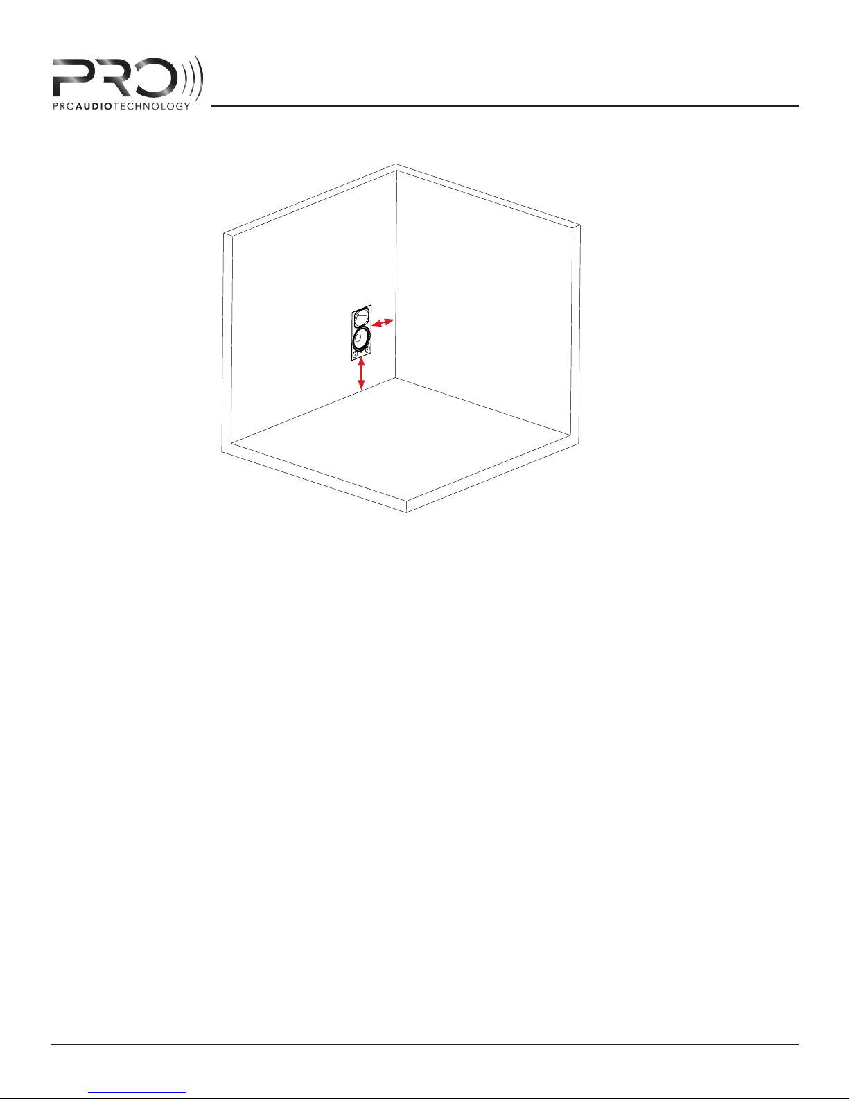
3 SURFACE LOADING
D
side
D
oor
In this case, the speaker is close
to two adjacent surfaces: the
side wall and the oor.
Try to avoid positions like this
whenever possible
D
= 0’ - 4’
side
D
= 0’ - 4’
oor
3 SURFACE LOADING - USE “3-SURFACES” FILTER
When the speaker is placed closer than approximately 4’ to two adjacent surfaces (i.e. both side wall
and oor) the low frequencies will be boosted dramatically. PMA Manager oers lters to compen-
sate for this eect based upon the approximate distance to the adjacent surfaces.
HIGH AND LOW PASS FILTERS
PMA Manager includes 80Hz high and low pass lters to facilitate the combining of subwoofer models with small (woofers 5” or smaller) “satellite” speakers in music and distributed audio applications.
Use the 80Hz high-pass lter on the satellite speakers to limit the LF energy and increase dynamic
range of the small speaker. On bi-amp installations apply the lter only to the woofer in the system.
For full-range (passive crossover models), apply the lter to the channel driving the full-range speaker.
PRO subwoofer speaker programs already have an 80Hz low-pass lter built-in, so no low pass lter
is necessary when using PRO subwoofers. If using a third-party subwoofer (watch out for PRO Brand
Loyalty Ninjas!) use the 80Hz low pass lter to restrict the bandwidth of the subwoofer to frequencies below 80Hz.
COMPENSATION FILTERS
26
Page 27
PMA AMPLIFIER SERIES
AMPLIFIER HOOKUP EXAMPLES
Pro Audio Technology loudspeakers are designed and built to professional audio criteria. As such,
their operation diers from typical ‘consumer’ grade speakers. Namely, most PRO speakers are bi,
tri or even quad-amplifer designs. This means that a separate amplier channel is required for each
transducer (loudspeaker driver) in the loudspeaker.
A bi-amp two-way speaker (i.e. SCR-12sm) requires two amplier channels; a tri-amp three way
model (i.e. SCR-2115sm) requires three amplier channels, etc.
Fortunately, PMA Manager allows signals input to a PMA chassis to be routed to any channel within
the chassis in the DSP chip to make such multi-amplication simple with a single interconnect from
the surround sound processor.
Below are some preamp/amp/speaker hookup examples.
FROM PREAMP “CENTER”
DSP ACTIVITY
STANDBY/PROTEC T
POWER
DISPLAY BACKLIGHT
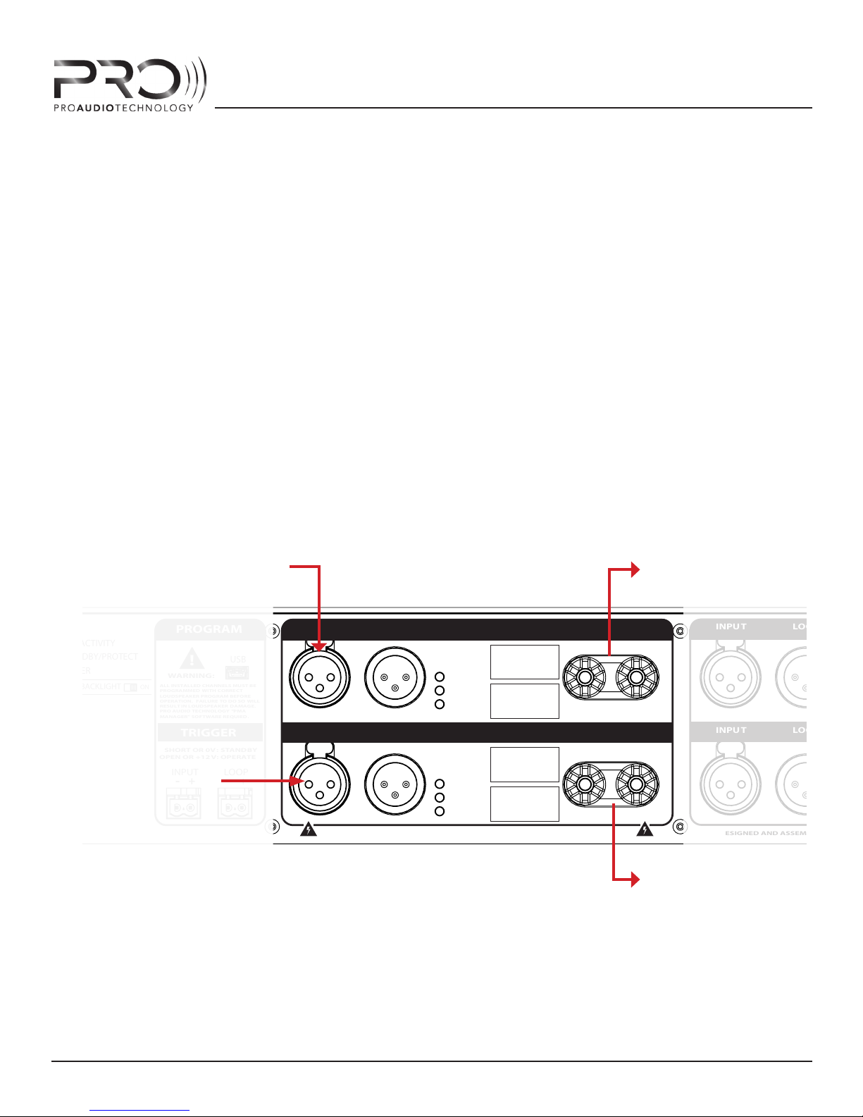
No input is required here because
we’ve programmed the amplier
Channel 2 to “listen to” the Channel
1 analog input using PMA Manager
PROGRAM
!
WARNING:
ALL INSTALLED CHANNELS MUST BE
ON
PROGRAMMED WITH CORRECT
LOUDSPEAKER PROGRAM BEFORE
OPERATION. FAILURE TO DO SO WILL
RESULT IN LOUDSPEAKER DAMAGE.
PRO AUDIO TECHNOLOGY “PMA
MANAGER” SOFTWARE REQUIED.
TRIGGER
SHORT OR 0V:
OPEN OR +12V:
INPUT LOOP
+
-
control software.
AMPLIFIER MODEL : PMA-4242
PMA MANAGER SIGNAL ROUTING:
CHANNEL 1 SOURCE : CHANNEL 1
CHANNEL 2 SOURCE : CHANNEL 1
OUTPUT
USB
STANDBY
OPERATE
+
-
TO LOUDSPEAKER
WOOFER
LOOPINPUT
LOOPINPUT
CHANNEL 1
PROGRAM
CLIP
SIGNAL
450W
SCR-12SM
CHANNEL 2
OUTPU T
-
OUTPU T
-
+
+
200W
PROGRAM
X
WARNING: SHOCK HAZARD. DO NO T OPEN. NO USER-SERVICEABLE PARTS INSIDED ESIGNED AND ASSEMBLED IN HUNTINGT
CLIP
SIGNAL
SCR-12SM
TO LOUDSPEAKER
TWEETER
LOOPINPUT
PROGRA
CLIP
SIGNAL
LOOPINPUT
PROGRA
CLIP
SIGNAL
TWO-WAY BI-AMP “CENTER CHANNEL” HOOKUP EXAMPLE
AMPLIFIER HOOKUP EXAMPLES
27
Page 28
PMA AMPLIFIER SERIES
PROGRAM
!
WARNING:
ALL INSTALLED CHANNELS MUST BE
ON
PROGRAMMED WITH CORRECT
LOUDSPEAKER PROGRAM BEFORE
OPERATION. FAILURE TO DO SO WILL
RESULT IN LOUDSPEAKER DAMAGE.
PRO AUDIO TECHNOLOGY “PMA
MANAGER” SOFTWARE REQUIED.
TRIGGER
SHORT OR 0V:
OPEN OR +12V:
INPUT LOOP
+
-
USB
STANDBY
OPERATE
-
FROM PREAMP
“CENTER” OUTPUT
LOOPINPUT
LOOPINPUT
+
X
WARNING: SHOCK HAZARD. DO NOT OPEN. NO USER-SERVICEABLE PARTS INSIDED ESIGNED AND ASSEMBLED IN HUNTINGT ON BEACH, CA BY PRO AUDIO TECHNOLOGY
AMPLIFIER MODEL : PMA-4242
PMA MANAGER SIGNAL ROUTING:
CHANNEL 1 SOURCE : CHANNEL 1 INPUT
CHANNEL 2 SOURCE : CHANNEL 1 INPUT
CHANNEL 3 SOURCE : CHANNEL 1 INPUT
CHANNEL 1
450W
PROGRAM
CLIP
SCR-2115sm
SIGNAL
LF
CHANNEL 2
200W 200W
PROGRAM
SCR-2115sm
CLIP
SIGNAL
HF
OUTPUT
-
OUTPUT
-
TO LOUDSPEAKER
WOOFER
+
X
+
TO LOUDSPEAKER
TWEETER
TO LOUDSPEAKER
LOOPINPUT
LOOPINPUT
CHANNEL 3
PROGRAM
CLIP
SIGNAL
CHANNEL 4
PROGRAM
CLIP
SIGNAL
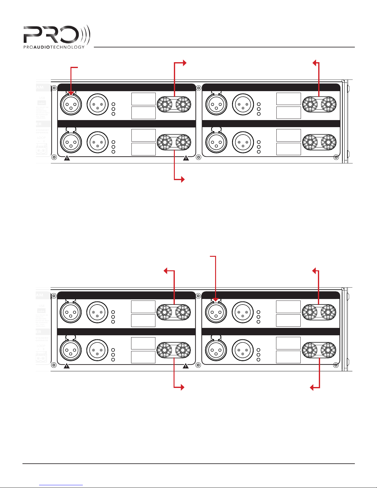
No input is required at X because
we’ve programmed the amplier
Channels 2 and 3 to “listen to” the
Channel 1 analog input using PMA
Manager control software.
MIDRANGE
450W
SCR-2115sm
MF
OUTPUT
-
OUTPUT
-
+
+
THREE-WAY TRI-AMP “CENTER CHANNEL” HOOKUP EXAMPLE
FROM PREAMP
“LFE” OUTPUT
PROGRAM
USB
!
WARNING:
ALL INSTALLED CHANNELS MUST BE
ON
PROGRAMMED WITH CORRECT
LOUDSPEAKER PROGRAM BEFORE
OPERATION. FAILURE TO DO SO WILL
RESULT IN LOUDSPEAKER DAMAGE.
PRO AUDIO TECHNOLOGY “PMA
MANAGER” SOFTWARE REQUIED.
TRIGGER
SHORT OR 0V:
OPEN OR +12V:
STANDBY
OPERATE
INPUT LOOP
+
-
-
LOOPINPUT
LOOPINPUT
+
X
WARNING: SHOCK HAZARD. DO NOT OPEN. NO USER-SERVICEABLE PARTS INSIDED ESIGNED AND ASSEMBLED IN HUNTINGT ON BEACH, CA BY PRO AUDIO TECHNOLOGY
AMPLIFIER MODEL : PMA-9942
PMA MANAGER SIGNAL ROUTING:
CHANNEL 1 SOURCE : CHANNEL 1 INPUT
CHANNEL 2 SOURCE : CHANNEL 1 INPUT
CHANNEL 3 SOURCE : CHANNEL 3 INPUT
CHANNEL 4 SOURCE : CHANNEL 3 INPUT
TO SUBWOOFER 1
CHANNEL 1
1000W
PROGRAM
CLIP
SCR-2115sm
SIGNAL
LF
CHANNEL 2
1000W
PROGRAM
SCR-2115sm
CLIP
SIGNAL
HF
FROM PREAMP
“CENTER” OUPUT
OUTPUT
-
-
+
OUTPUT
+
X
TO SUBWOOFER #2
No input is required at X because
we’ve programmed the amplier
Channels 2 and 4 to “listen to” input
Channels 1 and 3 respectively.
TO CENTER SPEAKER
WOOFER
LOOPINPUT
LOOPINPUT
CHANNEL 3
450W
PROGRAM
CLIP
SCR-2115sm
SIGNAL
CHANNEL 4
200W
PROGRAM
CLIP
SIGNAL
TO CENTER
SPEAKER TWEETER
MF
OUTPUT
-
OUTPUT
-
+
+
DUAL SUB / BI-AMP CENTER CHANNEL HOOKUP EXAMPLE
AMPLIFIER HOOKUP EXAMPLES
28
Page 29
PMA AMPLIFIER SERIES
AMPLIFIER PROGRAMMING
STOP!
To qualify to purchase and install PMA Amplifers you must rst complete PRO Training Full Program.
If you have not yet completed this course, do not attempt to program the ampliers yourself. Please
contact Pro Audio Technology at 1-800-272-6085 (outside the U.S. : 1-714-890-0418) to arrange training.
We’re serious. Dial the phone.
Besides, the training program is good, you’ll be glad you did it.
If you’re still reading, we’re going to assume that you’ve completed the training program - found it
to be both enlightening and profound - and are therefore ready to program your PMA amplier(s). If
not, be warned that PRO Traning Enforcement Ninjas will know it (they are Ninjas of the claravoiant
type), they will nd you and transport you, willingly or unwillingly, to the next scheduled training
course. Ninja-style. Or they will conscate your PMA ampliers. Or both.
Don’t risk it. Get the training.
PROGRAMMING OVERVIEW
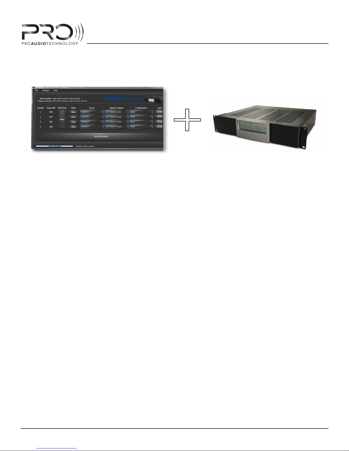
During the programming process, you will communicate with the DSP Engine inside the PMA amplier (using suppled PRO PMA Manager software) to install loudspeaker programs and auxillary lters
that will be used during operation to process the audio for the connected loudspeakers within the
system. You will also employ useful tools to aid in setup and diagnosis of the complex audio system.
This process is completed with the amplier connected to a Microsoft Windows (XP or 7) computer
via mini USB cable. These cables are readily available and are often supplied with digital cameras.
On one end there will be a standard USB conenctor, to be plugged into the PC, and on the other end
there will be a mini USB connector, to be plugged into the PMA amplier.
Each amplier within the audio system should be programmed, one-at-a-time. The USB cable can
easily be left connected to the PC then sequencially moved from one amplier to the next within the
system rack.
AMPLIFIER PROGRAMMING
29
Page 30

PMA AMPLIFIER SERIES
READ THIS SECTION
CONCEPTS TO KNOW
UNDERSTANGING THE RELATIONSHIP BETWEEN, AND THE ROLES OF, PMA AMPLIFIER DSP CHIP, PMA
!
AMPLIFIER MEMORY, AND PMA MANAGER SOFTWARE
If you read nothing else in this manual, READ THIS SECTION.
That said, however, if you do indeed read nothing else in this manual other than this section, you run
the likely risk of being summarily terminated as an Authorized PRO Dealer by PRO Dealer Authorization
Ninjas. This will happen when you’re not looking and when you least expect it. They are, after all, Ninjas.
Probably not worth it.
We’re kidding, of course, we don’t really have Ninjas of any kind, but we are serious when we say we
want you to get the training and read this manual in its entirety. For now, LEARN THESE CONCEPTS!
CONCEPT TO KNOW #1:
There are three places where the PMA amplier DSP settings can exist: within amplier memory,
within the amplier DSP chip itself, and within an (optional) backup le on your hard disk.
At many times during the programming process, the settings stored in these dierent locations
may be dierent or “out-of-sync”.
CONCEPT TO KNOW #2:
PMA Manager software allows control of settings currently running the DSP chip, oers a “view”
as to what these settings are, and facilitates the writing of the settings to the amp memory and
computer backup.
Only.
The software does not have any role during the running of the settings themselves inside the
DSP nor does it “store” any information within the software itself.
CONCEPT TO KNOW #3:
Each time a PMA amplier is powered-up, the DSP chip is intially “empty” - it does not remember
any of the lter settings or programs.
At power-up, an on-board micro processor loads the DSP parameter settings from on-board amp
memory.
AMPLIFIER PROGRAMMING
30
Page 31

PMA AMPLIFIER SERIES
CONCEPT TO KNOW #4:
When PMA Manager sofware is communicating to a connected PMA ampler, any changes made
to the controls within the software are loaded into the amplier DSP chip in real time and changes will be heard through the connected loudspeakers.
At this point, however, these settings exist only in the running DSP chip - they are not yet stored in
amp memory, nor on
CONCEPT TO KNOW #5:
In order for a PMA amplier to “remember” DSP settings when powered o and then powered up
again, your settings must be stored into the on-board ash memory so that they can be loaded by the
microprocessor during the power-up “initialization” process.
your PC.
CONCEPTS TO KNOW SUMMARY:
1 - DSP SETTINGS CAN EXIST IN THREE PLACES:
1. DSP CHIP
2. MEMORY
3. HARD DISK (IF YOU SAVE AN OPTIONAL BACKUP FILE).
2 - PMA MANAGER SOFTWARE IS JUST AN INTERFACE.
IT ALLOWS CONTROL AND A VIEW OF THE DSP SETTINGS THAT ARE RUNNING AND FACILITATES
SAVING SETTINGS TO THE AMP AND TO YOUR HARD DISK. IT DOES NO PROCESSING NOR STORING OF SETTINGS.
3 - THE AMP WON’T REMEMBER DSP SETTINGS WHEN POWERED OFF AND BACK ON UNLESS
YOU STORE THEM IN THE AMP MEMORY.
4 - AVOID NINJAS - GET THE TRAINING AND READ THE ENTIRE MANUAL.
AMPLIFIER PROGRAMMING
31
Page 32

PMA AMPLIFIER SERIES
PROGRAMMING STEPS
STEP 1 : MAKE A PLAN
Identify and take inventory of amplier models and installed powers as this information will determine which program is installed into which ampliers and on which channels. A detailed list of amp
channels with corresponding target loudspeaker drivers systems should be generated from the system design. Also note any compensation lter that will be required for a particular speaker or driver
(i.e. perforated screen lters for HF drivers in the LCR speakers).
CAUTION: DO NOT SKIP THIS STEP! A LARGE SYSTEM CAN BE VERY COMPLICATED, WITH
AS MANY AS 10-20 INDIVIDUAL CHANNELS WHICH REQUIRE UNIQUE ROUTING AND PRO-
!
GRAMMING. DOUBLE CHECK THE LIST FOR ACCURACY AND HAVE IT ON-HAND WHEN SITTING DOWN TO PROGRAM THE AMPLIFIERS.
STEP 2 : CONNECT AMPLIFIER TO COMPUTER
With the computer powered-on and fully booted, but with the amp o, connect the amplier to an
available USB port on your Windows XP or Windows 7 PC using a USB to mini USB cable. Plug the
standard USB connector into the PC port and the mini USB connector into the amplier USB port
located on the amplier back panel (see “Hardware Features - Back Panel” for more information).
STEP 3 : POWER ON AMPLIFIER
Connecting to a PC for the rst time - Internet Connection Required
If this is the rst time you’ve connected a PMA unit to your computer, Windows will need USB
drivers to establish communication with the unit.
Power-on the PMA amplier.
Windows will “see” the PMA unit and attempt to install the required USB drivers. If the drivers are
not available on your system, Windows will need access to the internet to nd them. If an internet connection is available, Windows will nd the drivers and install them automatically. This
may take a few minutes.
Once the drivers are installed, Windows will connect to the PMA unit and then show a brief message showing the PMA model and serial number just above your task pane on your screen. On
subsequent connections, Windows will install the driver more quickly.
Connecting to a PC - Subsequent Connections - No Internet Connection Required
Once the drivers have been loaded onto your system, Windows will discover and load the drivers
to the chosen USB port quickly. Sometimes this happens so fast you will not see a message from
Windows that your hardware is connected and ready for use, but you may hear a tone from the
operating system indicating new hardware is installed.
Operating systems other than Windows XP and Windows 7 are not supported.
AMPLIFIER PROGRAMMING
32
Page 33
STEP 4 : RUN PMA MANAGER SOFTWARE
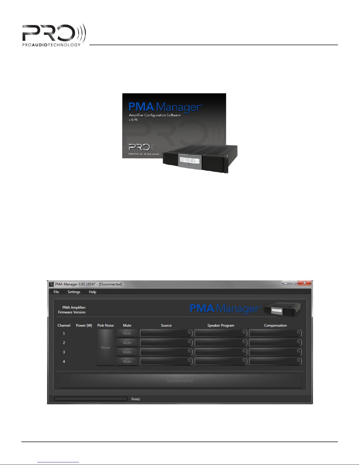
PMA MANAGER SPLASH SCREEN
PMA AMPLIFIER SERIES
Once communication between the computer and amplier has been established (you may see a
“your hardware is fully installed and is ready to use” message from Windows when this happens), run
the PMA Manager Software by selecting START -> PROGRAMS -> PRO -> PMA MANAGER from your
Windows menu or double-click the shortcut placed on your desktop. PMA Manager will open and
begin to establish a link to the connected PMA Amplier.
The PMA Manager initial or “splash” screen will appear and will stay on the screen while the software
loads. The splash screen will display the installed version of the software.
Once PMA Manager has initialized, the main graphic interface (GUI) will display.
PMA MANAGER GUI IN DISCONNECTED STATE
AMPLIFIER PROGRAMMING
33
Page 34

PMA AMPLIFIER SERIES
If PMA Manager has successfully established communication with the amplier, it will display “CONNECTED” in the program title bar and will list the amplier model, serial number and installed rmware version in the Information Pane of the GUI (to the left of the amplier image).
If connection could not be established, “DISCONNECTED” will show in the title bar and all components of the GUI will appear gray. No information will be displayed in the Information Pane. If this
happens, check the connections of the USB cable and make sure the amp is powered-on.
If the cable is connected properly and the amp is powered on but no connection was established,
close PMA Manager (File -> Exit or by clicking the red X in the upper right corner) then unplug the
USB cable from the computer, wait a few seconds, then plug it back in. Look for an acknowledgment from Windows that it has discovered the amp. This procedure will force Windows to load the
required USB driver if it has not already done so. Now re-launch PMA Manager and wait to see if a
connection is established. If PMA Manager still cannot connect to the amp lifer, refer to “Troubleshooting” section at the back of this manual for more information.
STEP 5 : SET DSP PARAMETERS FOR EACH AMPLIFIER CHANNEL
5a. Set Signal Routing
Each channel of the PMA amplier can “listen to”, or be routed to, any of the four XLR analog balanced audio inputs, or to the internal pink noise generator. The inputs and the noise generator
are referred to as “sources”.
To accomplish this routing, left-click on the drop-down list control under the Source column
heading. You will see a list of the ve available sources. Select the desired source by left-clicking
the desired source name in the list.
The selected source name will appear in the drop down control and PMA Manager will write to
the DSP to establish the signal-path change.
5b. Set Loudspeaker Program
Each channel of the PMA amplier can be programmed to power any PRO loudspeaker driver or
system, or can be programmed to pass audio unchanged (at) for use with third-party passive
loudspeakers.
To program an amp channel for a particular speaker program, left-click on the drop down list
control under the Speaker Program column in the GUI. You will see a complete list of all available
programs. Select the desired program by left-clicking the program name in the list.
The selected program will be loaded into the DSP and the program name will appear in the dropdown list control.
CAUTION: TAKE EXTRA CARE WHEN PROGRAMMING MULTI-WAY, MULTI-AMP LOUDSPEAKERS MAKING SURE TO ROUTE AND PROGRAM THE CORRECT SPEAKER PROGRAM FOR THE
!
DRIVER FOR WHICH YOU ARE CONNECTED. IF YOU ACCIDENTALLY WIRE AN LF (LOW-FREQUENCY) PROGRAM INTO AN AMP CHANNEL THAT IS CONNECTED TO AN HF (HIGH-FREQUENCY) UNIT AND ATTEMPT TO OPERATE THE SYSTEM, LOUDSPEAKER DAMAGE COULD
RESULT.
AMPLIFIER PROGRAMMING
34
Page 35

PMA AMPLIFIER SERIES
5c. Set Required Compensation Filter (if required)
Each channel of the PMA amplier can be programmed to apply a compensation lter for certain
acoustic conditions that may exist within the listening space that could alter the performance of
the loudspeaker in-situ. Some of these conditions are: the presence of a perforated video screen
in front of the screen speakers, nearby room boundaries or cloth that is stretched over listening
room walls that contain the speakers.
These lters are designed by Pro Audio Technology engineers to precisely compensate for the
particular acoustic condition. No knowledge of science, acoustics or engineering is required to
use them.
To program an amp channel for a particular compensation lter, left-click on the drop-down
list control under the Compensation heading in the GUI. You will see a complete list of available
lters. Select the desired lter by left-clicking the lter name in the list.
The selected lter will be loaded into the amplier DSP for that channel and the name of the lter
will appear in the drop-down control in the GUI.
ADVANCED SOFTWARE FEATURES
Certain features of PMA Manager software can only be accessed after ADVANCED CONTROLS have
been activated. These controls include individual channel gain adjustment and low-frequency parametric EQ lters.
To access these controls, go to the main menu SETTINGS -> ENABLE ADVANCED CONTROLS.
The GUI will expand and reveal the advanced objects.
5d. Set Channel Gain Level (if required) - ADVANCED
The overall gain (output level) of each PMA amplier channel can be adjusted with 0.1dB accuracy.
CAUTION: This feature is NOT intended to be used to match the surround sound acoustic
output levels of speakers within a surround sound system. The preamp/processor should
!
be used to set speaker level matching delay.
To adjust the gain of an amp channel, left-click on the button under the LEVEL heading in the
GUI. This will open up a new window, or form, with a volume slider and text entry eld. To execute an adjustment, left-click-and-hold on the on the slider scale (virtual sliding volume control)
and drag up or down to the desired setting. The exact value of the adjustment will appear in the
text box above the slider. Once the target value is reached, release the left mouse button and PMA
Manager software will load the setting into the amp DSP.
For precise adjustments, it may be easier to type the desired gain setting directly into the text
box on the gain form. To do this, left-click and drag to highlight ALL the text in the text eld, then
release the left mouse button and type in your desired setting. Hit ENTER (RETURN) and PMA
Manager will load the setting into the DSP.
NOTE: You must hit the ENTER or RETURN key after typing in the text box to execute the change.
AMPLIFIER PROGRAMMING
35
Page 36

Once the desired setting has been entered and conrmed, close the gain slider control by leftclicking on the CLOSE button at the bottom of the form.
CAUTION: IT IS NOT RECOMMENDED TO ADJUST THE GAIN SETTINGS OF AMP CHANNELS
CONNECTED TO DRIVERS WITHIN A MULTI-WAY SPEAKER SYSTEM RELATIVE TO ONE AN-
!
OTHER. THE RELATIVE LEVELS OF LOUDSPEAKER DRIVERS WITHIN A SPEAKER SYSTEM ARE
CAREFULLY OPT MI ZED DURING PRODUCT DESIGN AND ANY CHANGE TO THESE LEVELS
WILL ALTER THE ACCURACY THE REPRODUCED SOUND - THE VERY REASON FOR WHICH
YOU SELECTED A PRO LOUDSPEAKER IN THE FIRST PLACE!
DON’T DO IT!
STEP 6 : STORE DSP PARAMETERS IN AMPLIFIER MEMORY
This is the most important step, as failure to complete it will cause you to lose all your settings if
the amp is powered o.
Once the settings for all installed channels have been set in the software GUI (and therefore
transferred to the running DSP chip), the settings must be stored in the amplier memory so they
can be reloaded the next time the amp is powered on. If they are not stored into memory, next
time the amp power is cycled, the previously stored settings will load into the DSP.
PMA AMPLIFIER SERIES
Carefully inspect all settings for the connected amp in the GUI. In particular make sure that drivers within a multi-way speaker are routed to the same analog input. Make sure that woofer drivers are connected to the correct low-frequency (LF) speaker programs and that high-frequency
drivers are connected to the correct (HF) programs. Check that the correct compensation lters
(if any) are loaded into the channels of the correct drivers. For example, screen compensation
should be applied only to HF drivers; room boundary compensation only to LF drivers, etc.
When you’re convinced that everything is correct, left-click the full-width “UPDATE AMP MEMORY” button that appears just under the controls in the GUI. PMA Manager will write all settings to
the amp non-volatile memory so that they can be loaded every time the amp powers on. A progress bar will appear indicating the status of this process. Once completed, the progress bar will
close and the UPDATE AMP MEMORY button and asterisks on the front panel display will disappear indicating that the settings in the DSP have been successfully written to AMP memory.
AMPLIFIER PROGRAMMING
36
Page 37

PMA AMPLIFIER SERIES
TROUBLESHOOTING
PROBLEM: THE SIGNAL LED INDICATES THAT SIGNAL IS GETTING TO THE AMPLIFIER CHANNEL, BUT
NO SOUND IS HEARD.
CAUSE 1: AMP CHANNEL IS MUTED
Make sure the amp channel was not muted in by software control. Inspect the amplier front
panel display for the channel in question and observe the second column text for channel
routing; make sure “MUTE” is not shown. If you see “MUTE” that means that the channel was
muted in by PMA Manager software.
REMEDY:
To un-mute the channel to allow audio to be heard again, connect to the amplier with PMA
Manager software (refer to “Amplier Programming” section of this manual). Once connection is established, the muted channel should appear with the “Mute” button engaged (text
on the button is blue). To un-mute it, left-mouse-cllck the button to toggle the mute control,
audio will now be heard and the text on the mute button will be white indicating an “OFF”
condition.
Store the setting into the amplier memory by pressing the “UPDATE AMPLIFIER” button.
CAUSE 2: AMP IS IN PROTECT OR STANDBY MODE
Make sure the amp is not in standby or protect mode. Inspect the STANDBY/PROTECT LED
near the main power switch on the rear panel. If this LED is illuminated, the amp is in standby or protect mode and all channel power ampliers are disengaged. You can also tell amp
status from the front panel. If the amp is in STANDBY or PROTECT mode, the LCD backlight
will be dim with text showing and the blue power LED will be OFF.
REMEDY:
Determine if the mode is STANDBY or PROTECT by unplugging any wires connected to the
TRIGGER input or looping output. If the STANDBY/PROTECT LED goes out, this indicates that
the amp was receiving a STANDBY signal on its trigger input. This can be a short or a connection to DC trigger output with no voltage present. If this condition is not desired, nd the
problem with the other components or control system in the system.
If the STANDBY/PROTECT LED indicator is still illuminated, the amp is in PROTECT MODE and
a fault has occurred. This could be due to a short on the amp outputs, an over temperature
condition or some other fault within the amplier. See PROBLEM : AMP IS IN PROTECT MODE
below.
CAUSE 3 : NO SPEAKER PROGRAM IS LOADED INTO THE AMP CHANNEL DSP
When the PMA amp is shipped from the factory, no speaker programs are loaded into amp
channels by default. This is done to prevent unprocessed audio signals from passing that
could damage sensitive components (i.e. high-frequency drivers) within the loudspeaker
systems. When this condition exists, the word “NONE” will appear on the front panel display
and in the connected GUI Speaker Program control and no audio will pass for the channels in
question. The PROGRAM LED on the rear amp panel will not be illuminated.
TROUBLESHOOTING
37
Page 38

PMA AMPLIFIER SERIES
REMEDY:
Inspect the PROGRAM LED on the amp rear panel for the channel in question to determine if
a valid speaker program is loaded into the DSP for the channel in question. If a valid speaker
program is loaded, the PROGRAM LED will be illuminated. This LED will be o, otherwise.
Alternatively, you can inspect the software GUI (when connected to the PMA amp), or the
front panel display to determine the name of the speaker program installed into the DSP on
the channel in question. If it is the “NONE” program, change it to the desired program.
CAUSE 4 : THE CHANNEL IS ROUTED TO A DIFFERENT SOURCE, OR TO THE INTERNAL PINK NOISE
GENERATOR
It’s possible that he channel in question is routed to the incorrect input or to the internal
noise generator.
REMEDY:
Connect to the amp with PMA Manager or inspect the front panel display to determine to
what source the channel is routed. If it is routed, or “listening to”, the wrong source, use PMA
Manager to change the routing to the correct source.
Connect PMA Manager to the amp and establish a connection. Left-click the drop-down list
control under the SOURCE heading for the channel in question. A list of available sources will
appear. Left-click on the desired source name to load it into the DSP. Then, left-click the fullwidth UPDATE AMPLIFIER MEMORY button to store the settings in the non-volatile on-board
memory.
PROBLEM : AMP IS IN PROTECT MODE
CAUSE : A FAULT HAS OCCURRED INSIDE OR OUTSIDE THE AMPLIFIER
The amp will enter PROTECT MODE when one of following conditions exists: there is an overcurrent fault caused by a very low impedance or short at the amplier outputs; an amplier
power module has overheated to due extended high output use or unusually high ambient
temperature; or, a internal amplier component has failed.
REMEDY:
Disconnect the loudspeaker wires from the binding posts one at a time and observe the
STANDBY/PROTECT LED. If the LED goes o after disconnecting a wire, it is likely that the
wire has a short in it or is connected to a shorted loudspeaker. Correct the short and reconnect.
If no shorts are discovered and if after disconnecting all speaker wires from the amp, the
PROTECT status persists, an over temperature condition or a fault within the amplier has occurred.
To determine PROTECT mode was brought on by over temperature, with all wires disconnected, turn the main power switch o and leave the amp o for ten to twenty minutes to allow
the amplier to reach ambient temperature. Then power the amp on and observe the PRO-
TROUBLESHOOTING
38
Page 39

PMA AMPLIFIER SERIES
TECT LED. If it comes on immediately, a fault has occurred within the amp and it will need to
be returned to the factory for repair. If the LED does not come on, the amp should operate
normally.
PROBLEM: PMA MANAGER CANNOT ESTABLISH CONNECTION TO THE AMPLIFIER
While every eort was made to make PMA Manager and the PMA Ampliers robust and as bulletproof as possible, modern day PC’s are complicated devices with everyone’s PC being comprised
of a vast variety of diering hardware and software components. Software and hardware drivers
can interfere with one another and cause the system to act in unpredictable ways.
CAUSE 1 : PMA MANAGER IS INCORRECTLY IDENTIFYING ANOTHER HARDWARE DEVICE ATTACHED TO THE COMPUTER AS A PMA AMPLIFIER
This happens when the third party device that uses the same USB hardware interface as the
PMA Amplier (and therefore the same driver) is connected to the PC before the PMA Amplier. To Windows, these devices look the same.
REMEDY :
While programming PMA Ampliers, disconnect all other USB devices from your PC. This will
allow PMA Manager to easily identify and connect to the amp.
CAUSE 2 : WINDOWS HAS NOT LOADED THE CORRECT USB DEVICE DRIVER FOR THE PMA AMP
The rst time you connect a PMA amplier to your PC, Windows must locate and install USB
drivers for the PMA unit into your operating system. Normally, this will require access to the
internet so that Windows can nd the required les and copy them to PC hard disk.
REMEDY :
If you have not connected a PMA amplier to your PC when an internet connection is active
you will need to do so. It doesn’t matter which model or which particular PMA chassis you are
connected to do this, any PMA amplier will do.
TROUBLESHOOTING
39
Page 40
PMA AMPLIFIER SERIES
SPECIFICATIONS
Specication 2222 4242 4444 9900 9922 9942 9944 9999
Power Ch 1, 4 ohms 200W 450W 450W 1000W 1000W 1000W 1000W 1000W
Power Ch 2, 4 ohms 200W 200W 450W 1000W 1000W 1000W 1000W 1000W
Power Ch 3, 4 ohms 200W 450W 450W - 200W 450W 450W 1000W
Power Ch 4, 4 ohms 200W 200W 450W - 200W 200W 450W 1000W
Voltage Gain 27dB
Power Requirements, 1/8 Power,
pink noise, 120VAC,
all channels driven
Idle Power 32W
Standby Power 20W
Input Impedance 24k Ohms
Input Sensitivity
200W channels 1.3V
450W channels 1.9V
1000W channels 2.8V
Damping Factor
200W channels >200, 4-ohm load; >400, 8-ohm load
450W channels >200, 4-ohm load; >400, 8-ohm load
1000W channels >800, 4-ohm load; >1600, 8-ohm load
Frequency Response*
Idle Noise, at program, A-weighting
200W channels -78dBV (0.00013V)
450W channels -77dBV (0.00014V)
1000W channels -73dBV (0.00022V)
Idle Noise, speaker
program (typ.), Aweighting
200W channels -81dBV (0.00009V)
500W channels -80 dBV (.00010V)
1000W channels -76 dBV (0.00016V)
Signal to Noise
200W channels 108dB
450W channels 109.5dB
1000W channels 108dB
Distortion, 1kHz,
1dB below max
power output
Dimensions 19.0” W x 3.5”H x 16.7” D
Net Weight 13lbs. 14lbs. 15lbs. 15lbs. 16lbs. 17lbs. 17lbs. 20lbs.
Shipping Weight 18lbs. 19lbs. 20lbs. 20lbs. 21lbs. 22lbs. 22lbs. 25lbs.
92W
314 Btu/hr
109 Btu/hr
68 Btu/hr
136W
464 Btu/hr
38W
130 Btu/hr
26W
89Btu/hr
180W
614 Btu/hr
44W
150 Btu/hr
32W
109 Btu/hr
173W
590 Btu/hr
34W
116 Btu/hr
15W
51 Btu/hr
20Hz-20kHz +/- 0.2dB*
*1000W Ch 2 and 3 20Hz-3kHz +0,-3dB
<0.07%
215W
734 Btu/hr
46W
157 Btu/hr
21W
72 Btu/hr
237W
809 Btu/hr
49W
167 Btu/hr
24W
82 Btu/hr
259W
884 Btu/hr
52W
177 Btu/hr
27W
92 Btu/hr
338W
1153 Btu/hr
60W
205 Btu/hr
22W
75 Btu/hr
SPECIFICATIONS
40
Page 41

PMA AMPLIFIER SERIES
WARRANTY
Disclaimer : Professional Home Cinema, LLC (dba “Pro Audio Technology”) is not liable for any
damage to loudspeakers or any other equipment that is caused by negligence or improper use or
installation of this product.
Professional Home Cinema, LLC 3-Year Limited Warranty
Professional Home Cinema, LLC dba “Pro Audio Technology” (PHC) guarantees its products to be
free from defective materials and/or workmanship for a period of three (3) years from the date of
sale, and will replace defective parts and repair malfuctioning products under this warranty when
the defect occurs under normal installation and use - provided that the unit is returned to our
factory or one of our authorized service centers via prepaid transportation with a copy of proof of
purchase (sales receipt). This warranty provides that the examination of the return must indicate,
in our judgement, a manufacturing defect. This warranty does not extend to any poduct which
has been subject to misuse, neglect, accident, improper installation or where the date code has
been removed or defaced. PHC shall not be liable for incidental and/or consequential damages.
The warranty gives you specic legal rights. This limited warranty is not transferable. Customer
may have rights which vary from state to state.
In the event that this product was manufactured for export and sale outside of the United States
or its territories, then this limited warranty does not apply. Removal of the serial number on this
product, or purchase of this product from an unauthorized dealer will void this limited warranty.
Periodically this warranty is updated. To obtain the most recent version of PHC’s warranty statement, please call 1-714-890-0418.
CONTACTING PROFESSIONAL HOME CINEMA, LLC
Mailing address: 5445 Oceanus Drive
Suite 110
Huntington Beach, CA 92649
Telephone: Main: 714-890-0418
Toll Free: 800-272-6085 (US only)
Fax: 714-890-0536
Internet: www.professionalhomecinema.com
www.proaudiotechnology.com
WARRANTY
41
 Loading...