

Page 1
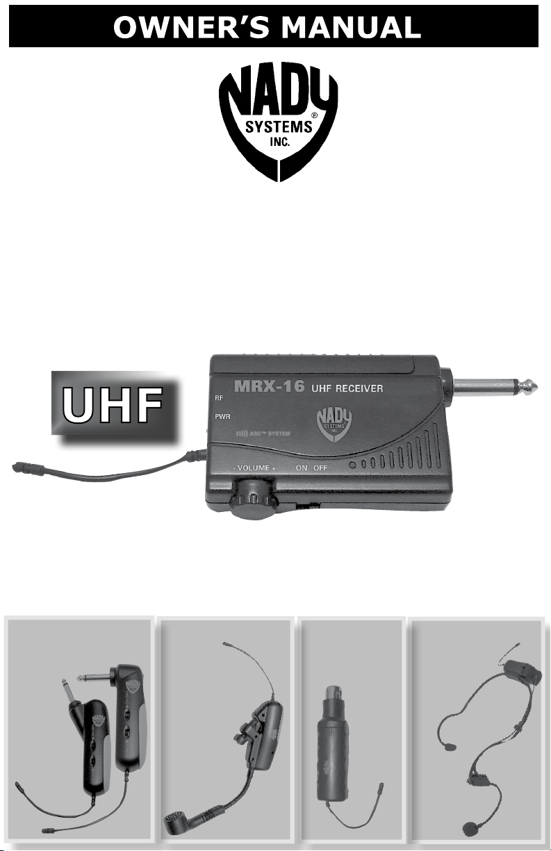
16-CHANNEL
MICRO WIRELESS
SYSTEM
MRX-16 RECEIVER
Instructions for use with any of these transmitters
micro
MGT-16 SYSTEM
MT-16A
MT-16R
micro
MHT-16 SYSTEM
MH-16
micro
LINK-16 SYSTEM
LK-16
WHM-16 SYSTEM
micro
WH-16
Page 2

Contents
Introduction ............................................................................. 2
Using this Manual ..................................................................... 2
System Features
microMRX-16/microMHT-16/microLINK-16/microWHM-16 .......... 3
Quick User Controls/Connections Guide ....................................... 4
MRX-16 Wireless Instrument Receiver ..................................... 4
MT-16A/R Instrument Transmitter ........................................... 6
MH-16 Horn Instrument Transmitter ........................................ 7
LK-16 Snap-On Transmitter .................................................... 8
WH-16 Head-Worn Transmitter ............................................... 9
System Operation ..................................................................... 10
MRX-16 Wireless Receiver ...................................................... 10
MT-16A/R, MH-16, LK-16, WH-16 Transmitters ......................................12
Miscellaneous Tips .................................................................... 14
Cautions and Troubleshooting .................................................... 15
MRX-16 System DIP-Switch Frequency Selection Chart .................. 16
Specications ........................................................................... 17
Servicing ................................................................................. 18
Warranty ................................................................................. 19
Introduction
Thank you for choosing the Nady microMGT-16/microMHT-16/
microLINK-16/microWHM-16 Mini Wireless System. Each of these units is
a 16-channel, ultra-compact UHF wireless system featuring 16 selectable
frequencies, up to 250 feet operating range, and infrared ASC
Sync Channel) for quick convenient setup. The miniature receiver can be
plugged directly into any amp or mixer.
TM
(Auto
Using This Manual
This booklet provides information regarding the use of the microMGT-16,
microMHT-16, microLINK-16 or microWHM-16 Wireless System with the
MRX-16 receiver and one of the following transmitters: MT-16A/R, MH-16,
LK-16 or WH-16. It includes a description of features and a step-by-step
guide to operation of the particular system you have purchased. This
manual should answer any questions you may have about the operation
and servicing of your
system.
2
Page 3

System Features
MRX-16 Systems
•
UHF wireless system for musical instrument sounding
•
16 user-selectable PLL frequencies for interference-free operation
•
Up to 250’ operating range, line-of-sight
•
ASCTM (Auto Sync Channel) infared wireless download pairs transmitters to selected
receiver frequency for quick, easy setup
• Battery operated receiver and transmitters
MRX-16 Instrument Receiver
•
Compact, portable, “pocket size” receiver
•
Flexible wire ¼ wave antenna
•
Unbalanced ¼” line output plug
• Power On/Off/Mute switch; Volume Control; LED indicators for Low Battery, and RF
Reception; DIP-switch channel selection with IR sync to transmitter; IR Sync LED
• Powered by one AA alkaline battery for portability (Up to 8 hours battery life)
Available Transmitters
MT-16A & MT-16R Instrument Transmitters
• Choice of two transmitter housings— MT-16A with 30° angled ¼” plug for use with
either recessed or surface mounted jacks, or MT-16R with 90° angled ¼” plug for
surface mounted jacks only
• Up to eight hours of battery life from a single AAA alkaline or NiMH rechargeable
battery
• Infrared channel sync with receiver for instant setup
• Power On/Off switch; Power/Low Battery LED indicators; IR Sync LED
• Input level attenuation switch; internal audio level control trim-pot
• External exible wire antenna
MH-16 Saxophone (Horn) Instrument Transmitter
• Clip-on-the-horn barrel style without any tangling wires
• Up to eight hours of battery life from a single AAA alkaline or NiMH rechargeable battery
• Infrared channel sync with receiver for instant setup
• Power On/Off switch; Power/Low Battery LED indicators; IR Sync LED
• Input level attenuation switch; internal audio level control trim-pot
• External exible wire antenna
LK-16 Snap-On Transmitter
• Female XLR input connector for mounting transmitter on any hardwired dynamic microphone
• Up to eight hours of battery life from a single AAA alkaline or NiMH rechargeable battery
• Infrared channel sync with receiver for instant setup
• Power On/Off switch; Power/Low Battery LED indicators; IR Sync LED
• External exible wire antenna
WH-16 Head-Worn Transmitter
• Head-Worn (over ears style) transmitter for hands free, cordless operation
• Up to eight hours of battery life from a single AAA alkaline or NiMH rechargeable battery
• Infrared channel sync with receiver for instant setup
• Power On/Off switch; Power/Low Battery LED indicators; IR Sync LED
• External exible wire antenna
3
Page 4
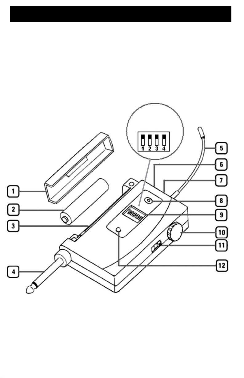
Quick User Controls/Connections Guide
MRX-16 Receiver
DIPSWITCH
EXPLODED
VIEW
AA
4
Page 5

Quick User Controls/Connections Guide
MRX-16 Receiver
1. BATTERY COMPARTMENT COVER Holds one AA battery, slide to
open
2. AA BATTERY One required for operation, alkaline or NiMH
3. BATTERY COMPARTMENT Insert one AA battery for operation, note
correct polarity
4. AUDIO OUTPUT PLUG For connecting to other sound equipment
(amp or mixer) input jack
5. ANTENNA Permanently attached exible antenna
6. RF SIGNAL LED (Green) Indicates the received signal from the
transmitter
7. POWER & LOW BATTERY LED (Red) Flashes once at power up,
continuous ashing battery needs replacement
8. ACS™ IR SYNC BUTTON Press to make the IR link download the
receiver’s selected frequency to the TX. First, turn on the transmitter
(or turn off and then on again if already on) and position its IR window
6-12” away from the RX IR window, press the SYNC button once
and wait one second for the RX to respond. If the IR data download
is successful, the receiver SIGNAL LED (6) will light indicating the
transmitter is locked in and transmitting.
9. CHANNEL SELECT DIP-SWITCH Select one of 16 pre-set channels
per MRX-16 DIP-Switch Frequency Selection Chart (see page 16)
10. VOLUME CONTROL Adjusts the audio output level—at maximum
setting the gain will be about +4dB over a direct instrument-to-cord-to-
amp connection
11. POWER SWITCH Select OFF/MUTE/ON (MUTE=power On, audio
output highly attenuated)
12. ACS™ IR SYNC INFRARED LED WINDOW For downloading
selected Channel (Frequency) to transmitter
5
Page 6
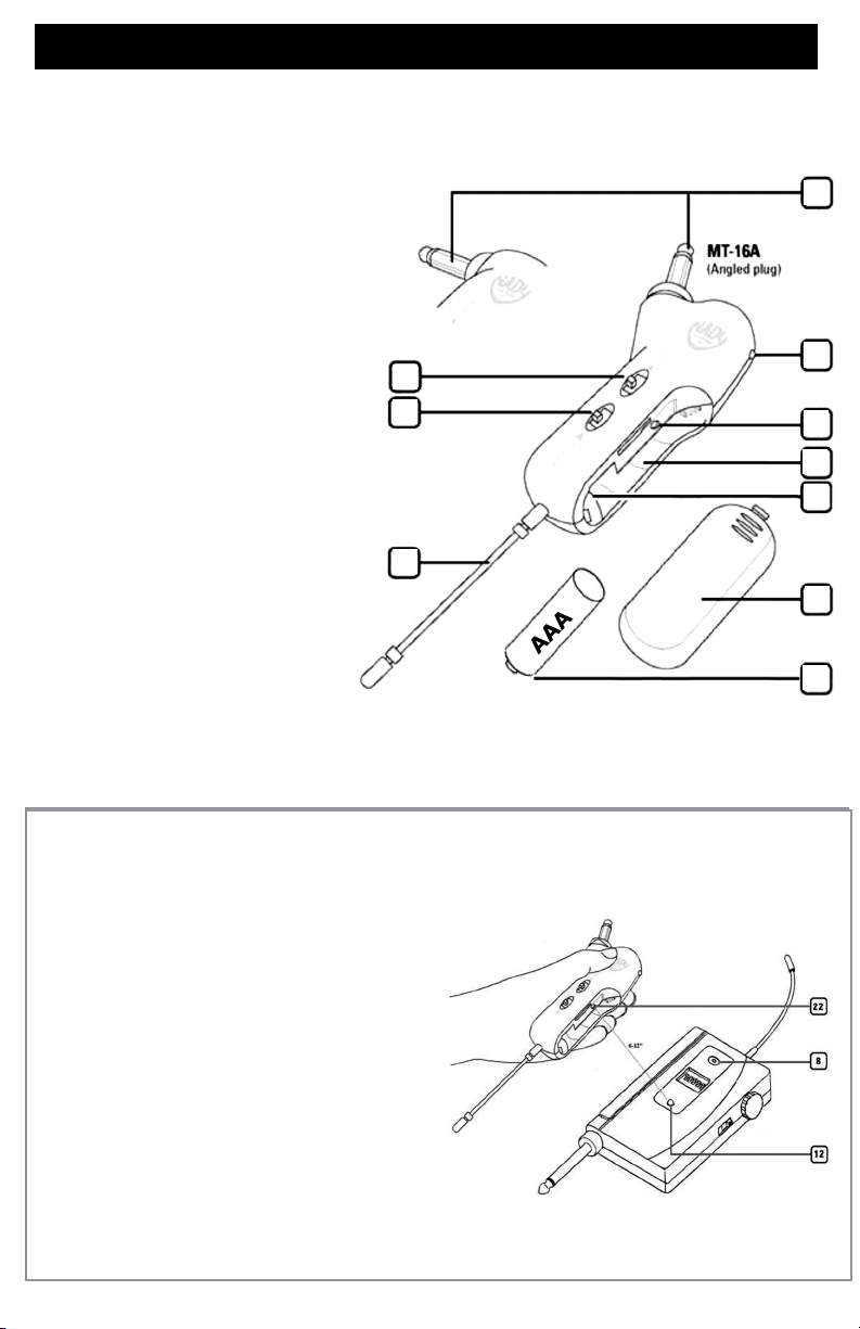
Quick microMGT-16 User Controls/Connections Guide
MT-16A/R Instrument Transmitter
17. POWER SWITCH Slide in arrow direction
to power transmitter On
18. 15dB ATTENUATION PAD Select to
reduce the input gain by 15dB for higher level
audio input signals
19. INPUT ¼” PLUG Connect directly
intoguitar/bass output jack
20. POWER & LOW BATTERY LED Flashes
once at power up, continuous ashing indicates
battery needs replacement
21. IR RECEPTOR SENSOR/WINDOW
Infrared LED sensor for linking the TX to the RX
during IR frequency download
22. BATTERY COMPARTMENT Insert one AAA
battery, observing correct polarity
23. INTERNAL AUDIO LEVEL ADJUST
Remove battery to access slot and adjust
internal trim-pot with small screwdriver for
optimal input level setting. Note: this is to be
done only in rare cases as factory level setting
is already optimized for most guitars and basses
and 15dB Pad also available.Note: Set control
carefully. If trim-pot is turned past minimum
and maximum adjustment points it may need to
be backed up to achieve desired setting.
18
17
24
19
20
21
22
23
26
24. ANTENNA Permanently attached exible
antenna
25. BATTERY Single AAA alkaline or NiMH
battery required for operation
26. BATTERY COMPARTMENT COVER Slide
to open
TM
ASC
IR Sync Download of Selected
Frequency of MRX-16 Receiver to
micro MT-16A/R, micro MH-16, micro
LK-16 or micro WH-16 Transmitter
(1) ASC™ IR SYNC INFRARED LED WINDOW
For downloading selected Channel
(Frequency) to transmitter
(21, 31, 46, 56) MT-16A/R, MH-16, LK-16, WH-16
TRANSMITTER IR RECEPTOR SENSOR/WINDOW
Infrared LED sensor for linking the TX to the RX
during IR frequency download.
(14) ASC
™
IR SYNC BUTTON Press to make the IR link
download the receiver’s selected frequency to the TX.
First, turn on the system transmitter supplied (or turn
off and then on again if already on) and position its
IR window 6-12” away from the RX IR window, press
the SYNC button once and wait one second for the
RX to respond. If the IR data download is successful,
the receiver SIGNAL LED (6) will light indicating the
transmitter is locked in and transmitting.
25
6
Page 7
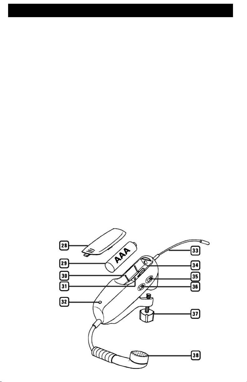
Quick microMHT-16 User Controls/Connections Guide
MH-16 Saxophone (Horn) Instrument Transmitter
28. BATTERY COMPARTMENT COVER To cover AAA battery, slide to open
29. BATTERY Single AAA alkaline or NiMH battery required for operation
30. BATTERY COMPARTMENT Insert one AAA battery, observing correct polarity
31. IR RECEPTOR SENSOR/WINDOW Infrared LED sensor for linking the TX to the RX
during IR frequency download (See also ASC
32. POWER & LOW BATTERY LED Flashes once at power up, continuous ashing
indicates battery needs replacement
33. ANTENNA Permanently attached exible antenna
34. INTERNAL AUDIO LEVEL ADJUST Remove battery to access slot and adjust internal
trim-pot with small screwdriver for optimal input level setting.
Note: This is to be done only in rare cases as factory level setting is already optimized for
most horns and 15dB Pad also available.
Note: Set control carefully. If trim-pot is turned past minimum and maximum adjustment
points it may need to be backed up to achieve desired setting.
35. POWER SWITCH Slide in arrow direction to power transmitter On
36. 15dB ATTENUATION PAD Select to reduce the input gain by 15dB for higher level
audio input signals
37. MOUNTING SCREW To secure the transmitter onto the bell of the horn
38. INPUT MIC For unidirectional pickup of horn’s sound
TM
IR Sync Download section, page 6)
7
Page 8
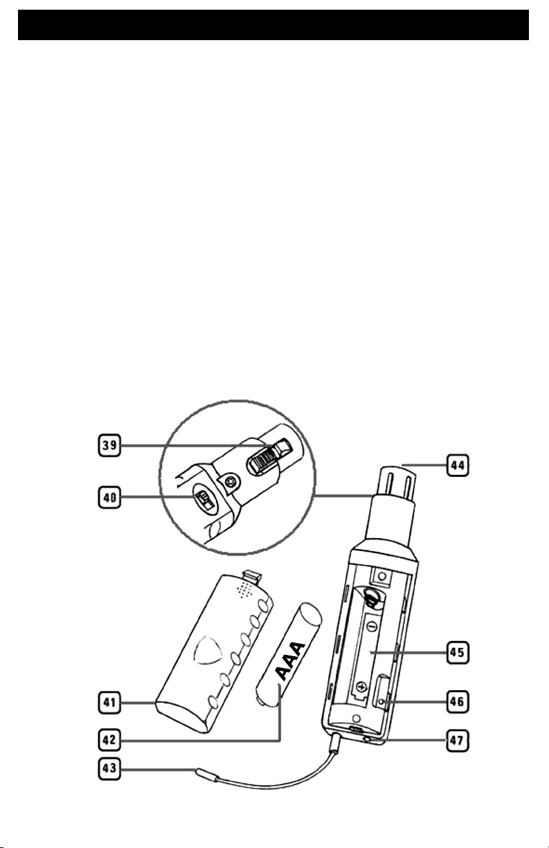
QUICK microLINK-16 SYSTEM USER CONTROLS/CONNECTIONS
GUIDE
LK-16 Snap-On Transmitter
39. XLR LOCKING CLIP To lock the hardwired microphone securely
40. POWER SWITCH Slide in arrow direction to power transmitter On
41. BATTERY COMPARTMENT COVER To cover AAA battery, slide to open
42. BATTERY Single AAA alkaline or NiMH battery required for operation
43. ANTENNA Permanently attached exible antenna
44. FEMALE XLR PLUG Accepts any hardwire MIC with male XLR connector
45. BATTERY COMPARTMENT Insert one AAA battery, observing correct polarity
46. IR RECEPTOR SENSOR/WINDOW Infrared LED sensor for linking the TX to the RX
during IR frequency download (See also ASCTM IR Sync Download section, page 6)
47. POWER & LOW BATTERY LED Flashes once at power up, continuous ashing indicates
battery needs replacement
8
Page 9
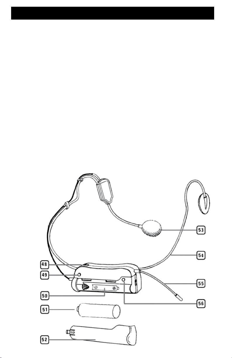
QUICK microWHM-16 USER CONTROLS/CONNECTORS
GUIDE
WH-16 Head-Worn Transmitter
48. POWER SWITCH Slide in arrow direction to power transmitter On
49. POWER & LOW BATTERY LED Flashes once at power up, continuous ashing
indicates battery needs replacement
50. BATTERY COMPARTMENT Insert one AAA battery, observing correct polarity
51. BATTERY Single AAA alkaline or NiMH battery required for operation
52. BATTERY COMPARTMENT COVER To cover AAA battery, slide to open
53. INPUT MIC Unidirectional pickup for vocals
54. FLEXIBLE HEADBAND For mounting over the ears
55. ANTENNA Permanently attached exible antenna
56. IR RECEPTOR SENSOR/WINDOW Infrared LED sensor for linking the TX to the RX
during IR frequency download (See also ASCTM IR Sync Download section, page 6)
AAA
9
Page 10

SYSTEM OPERATION
MRX-16 Receiver
Selecting the MRX-16 Receiver
Channel and IR Sync
Antenna
Antenna
The MRX-16 receiver is supplied with an attached
Antenna (5). It should be extended fully to
obtain maximum range. For maximum range,
it is always best to maintain a line-of-sight (no
obstructions) between the receiver antennas and
the transmitter whenever possible.
Powering the Receiver
The MRX-16 receiver can operate with either
two AA size batteries (DC operation) or with the
supplied AC adaptor (AC operation).
For DC operation, open the receiver’s
Battery Compartment Door (1) and
place a fresh AA Battery (2) in the Battery
Compartment (3), observing the correct polarity.
A fresh alkaline or NiMH AA battery will generally
provide 6-8 hours performance, but in order to
ensure optimal performance it is recommended
that the batteries be replaced after six hours of
use, or as indicated by the Low Battery Indicator
(7). As the battery begins to weaken below
usable voltage, the low battery indicator will ash
continuously, warning that the battery is now too
low and should be replaced as soon as possible. To
preserve battery life, keep the receiver Off when it
is not in use.
Turn on the MRX-16 receiver by sliding
the Power Switch (11) to the second
position (receiver On but audio output muted/
attenuated), or to the third position for normal
operation (receiver On and audio un-muted).
The Power & Low Battery LED (7) will ash
once indicating receiver is operational.
The Frequency Select DIP Switches
(9) are used for selecting one of 16
preset frequencies. Simply position the
DIP switches to a desired open channel
on the receiver. There should be no
ickering of the RF Signal LED (6) with
the transmitter off. See the MRX-16 DIP-
Switch Frequency Selection Chart on
page 16 for the correct switch position for
each of the 16 available channels. Once
you have selected the receiver frequency
it can easily be downloaded to the
transmitter to establish the necessary RF
connection. For further info on selecting
open channels, see RF Interference and
Finding Open Channels on page 15.
The IR Sync Button (8) on the MRX-16
receiver
frequency info from the receiver to the
transmitter for quick synchronization prior
to use. Begin programming by holding
the wireless transmitter’s IR Receptor/
Sensor Window (21, 31, 46, 56) about
6-12” from the receiver’s IR Synch
Infrared LED Window (12). Press the
IR Sync Button once to begin the IR sync
download of the selected frequency to the
transmitter.
Note: To insure proper synchronization, the
transmitter must always be just turned on, or
else turned off then on again, before syncing
is used to transfer the selected
10
Page 11
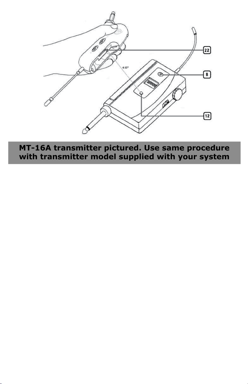
MT-16A transmitter pictured. Use same procedure
with transmitter model supplied with your system
When the RF Signal LED (6) on the
receiver lights up, the system frequency
is properly synchronized. To change
to a different frequency, reset the
Frequency Select DIP Switches (9)
and sync the transmitter again to the new
selected frequency rst, after turning the
transmitter off and then on again. If no
action is taken during the 10 seconds of
active data transfer ( i.e., the transmitter
is not turned on or properly positioned)
the receiver and the transmitter units
do not link and transmitter’s previously
programmed channel remains unchanged.
Note: Only one transmitter can be used
with one receiver. It is not possible to use
two transmitters on the same frequency
and mix the output of these transmitters
into one wireless receiver.
Note: The IR link is infrared light and
works best when this data transfer is
accomplished in a light-shielded or darker
environment. It may not be successful
in a brightly lit area. If the transfer fails,
repeat the procedure in a darker location or
somehow shield the link from outside light
to successfully program the transmitter
with the selected channel info from the
receiver.
Connecting Audio Output
The MRX-16 receiver’s Audio Output
Plug (4) is a ¼” unbalanced line out
and its level is controlled by the Volume
Knob (10). Plug into your pedal board or
amplier/mixer as you would with a direct
cord from the instrument or mic. When the
Volume knob is set to maximum receiver
volume setting, the system audio output
is approximately +4dB higher than a
direct instrument (or mic)-to-cord-to-amp
connection.
Note: As when making any connection,
make sure the amplier volume control is
set at the minimum level before plugging
in the receiver to avoid possible speaker
damage.
Your MRX-16 receiver is now operational
and ready to use. Once you have
completed the above steps, proceed to the
following instructions for the transmitter
model supplied with your system.
11
Page 12

SYSTEM OPERATION
MT-16A/R, MH-16, LK-16, or WH-16 Transmitter
Note: The transmitter referred to below is
one of the following: MT-16A/R, MH-16,
LK-16 or WH-16, as provided with your
system.
Powering the Transmitter
The transmitter each requires one AAA
Battery (25, 29, 42, or 51). To install
the battery, push the locking tabs on
the Battery Cover (26, 28, 41, or 52)
and push out to expose the Battery
Compartment (23, 30, 45, or 50).
Insert one fresh AAA battery according
to the correct polarity as indicated on
the transmitter body. Close the battery
cover, ensuring the cover is snapped shut.
A fresh AAA alkaline battery generally
provides up to 6-8 hours of operation, but
in order to ensure optimal performance it is
recommended that the battery be replaced
after six hours of use or as indicated by the
Low Battery Indicator (21, 32, 47, or
49).
As the batteries weaken, the Low Battery
Indicator will ash to warn that the battery
level is too low and should be replaced as
soon as possible. To preserve battery life,
turn the transmitter off when not in use.
To turn the transmitter off, slide the Power
Switch in the opposite direction of the
arrow.
To turn on the transmitter, slide the
Power Switch (17, 35, 40, or 18) in the
direction of the arrow. The Low Battery
Indicator will ash once. The unit is now
on and the receiver’s RF Signal LED (6)
will light up if the transmitter has been
frequency synchronized to the receiver’s
selected frequency as per below. To turn
it off, slide the power switch opposite
direction, and the receiver RF Signal LED
(6) should be off.
The transmitters (MT-16A/R, MH-16 only)
have a 15dB Pad (18) switch which can
be selected to attenuate high output from
instrument pick-up levels if needed to
reduce distortion through the system. To
attenuate, slide the switch in the direction
of the arrow. Turning opposite the arrow
indication is for standard 1:1 gain operation
and is recommended for normal, optimal
low-noise operation.
The transmitters (MT-16A/R, MH-16 only)
have an internal Audio Level Adjust (24,
34) to set the audio deviation level. It is
accessed by inserting a small screwdriver
into the slot. Turning this trim-pot
counterclockwise reduces overall system
audio output (thus lowering distortion but
raising background noise), while turning
clockwise increases overall system audio
output (thus lowering background noise but
raising distortion). The Audio Level Adjust
is factory set to the mid position, which is
the optimal setting for normal operation.
Note: The Audio Level Adjust is not
intended for high-input signal adjustment—
the 15dB pad is provided for that purpose.
It is for use only in extreme cases during
which satisfactory audio cannot be achieved
with the pad alone.
Note: Set control carefully. If trim-pot
is turned past minimum or maximum
adjustment points, it may need to be
backed up to achieve desired setting.
12
Page 13

The transmitters (LK-16 and WH-16)
have a xed input level. The Audio
Level is factory set to the optimal
setting for normal operation. The
audio levels should be obtained via
the receiver volume control only. (See
Connecting Audio Output section on
page 11).
Programming The Transmitter
to the Selected Channel
Before beginning operation, the
transmitter must be synchronized
with the selected frequency from the
receiver using the IR Receptor/
Sensor Window (22, 31, 46 or 56)
on the transmitter and the IR Sync
Window (12) on the receiver (see
Selecting the MRX-16 Receiver
Channel and IR Sync on page 10).
After rst turning the transmitter on
(or off and then on again if already
on), begin programming by holding
the transmitter’s IR Receptor/
Sensor Window about 6-12” from the
receiver’s IR Synch Window. Press
the IR Sync Button (8) on the
receiver once to begin the IR sync
download of the selected frequency
to the transmitter. Upon successful
data transfer (usually in less than
two seconds) the transmitter will
transmit a radio signal on the same
channel (frequency) as the receiver.
The Signal LED (6) on the receiver
will light up, indicating that the link is
completed. If all the necessary steps
noted above are not taken during
the 10 seconds of active data transfer,
the receiver and the transmitter units
will not link and the transmitter’s
previously programmed channel
remains unchanged.
Operating the Transmitter
(MT-16A/R, MH-16, LK-16, or WH-16)
During normal operation with the unit
powered on, the MT-16A/R transmitter
should be fully inserted into the instrument
(guitar, bass, etc.), or the MH-16 attached
to the sax, or the LK-16 attached to the
hard-wired mic or the WH-16 placed on
the head. When ready to play, slide the
Power Switch (17, 35, 40, or 48) to
ON position in the direction of the arrow.
The receiver Signal LED (6) should light
up if system is properly synchronized.
Adjust the volume on the receiver (see
Connecting Audio Output on page 11)
for unity gain (one-to- one) with a hardwired cord. Or, (MT-16A/R, MH-16 only)
select up to an added 4-5dB boost by
adjusting the receiver volume to maximum
for normal use with guitars and bass
guitars. A listening test prior to use will
determine which receiver volume and
transmitter input pad settings are best
for your application. To mute/un-mute
(attenuate) the audio during use, set the
receiver power switch to the second (Mute)
position. Or, just turn off the transmitter
with the power switch. The signal LED
will turn off and the audio will be muted
(Off). When ready to play again, slide the
receiver’s power switch to the third (On)
position. Or, just turn on the transmitter.
When programming is nished,
close the battery compartment
door, ensuring that it latches. The
transmitter is now ready for use.
Note: Manually matching the
transmitter frequency without the
receiver is not possible. For proper
operation, the transmitter must have
the same channel as selected on the
receiver. Only one transmitter can be
IR synced and work with one receiver,
but one transmitter can work with
many receivers.
13
Page 14

Miscellaneous Tips
• The receiver antennas should be kept away from any metal surfaces whenever
possible as they can reect away or shield the incoming RF signal.
• When inserting batteries, make sure they are inserted with the correct polarity.
• Before operation, conrm that the receiver and associated transmitter are
tuned to the same frequency/channel.
• After making a receiver channel change, make sure that the corresponding
change is also made on the matching transmitter.
• Use only fresh alkaline or fully charged NiMH batteries. Do not use “general
purpose” carbon batteries. When batteries are weak, replace all of them at the
same time. Do not mix new and old batteries, or different types of batteries.
• Position the receiver so it has the least possible obstructions between it and
the transmitter. Line-of-sight is best.
• During operation, the transmitter and receiver should be as close as possible to
each other for optimal results.
• A receiver cannot receive signals from two or more transmitters
simultaneously.
• Turn the transmitter off when it is not in use. For longest life, remove the
batteries if the unit is not going to be used for a long period of time as the
transmitters draw a tiny residual current even when off in order to maintain
the programmed settings. Also, since batteries installed for a long time can
sometimes corrode and/or leak, causing damage, it is generally recommended
that batteries be removed whenever the transmitters are not being used.
• When using the MT-16A/R with guitars and basses: Scratchy noises can
sometime occur when electric guitars with dirty pots or connections are used
with a wireless system. If you hear scratchy noises, we suggest these steps to
eliminate them:
1. Make sure all guitar volume and tone pots are clean and all contacts
are solid. This is very important.
2. Solder a 47pF capacitor across the pot to ground terminal of the
guitar’s volume and tone pots — this will provide extra ltering.
14
Page 15

Cautions and Troubleshooting
Low or no audio
If you are not getting audio through the system, carefully re-check all setups. Especially
note that the receiver and transmitter must be set to operate on the same RF channel.
Make sure that the Power Switch (11) on the MRX-16 receiver is not in the second
position (audio muted/attenuated). The receiver’s Audio Output (4) is adjustable, so
make sure the Volume Control (10) is set properly.
RF Interference and Finding Open Channels
If you receive interference on a selected channel with the transmitter off, you must
reprogram the receiver and transmitter to a different channel.
To reprogram, you must rst nd an open channel. To do this, follow the operating
procedure outlined in Selecting the MRX-16 Receiver Channel and IR Sync on page
10. With the transmitter off, change the receiver DIP Switches (9) setting to one of
the 16 channels until you nd one for which the Signal LED (6) doesn’t icker or light
up. Also, for optimal interference-free operation, the Signal LED must not icker or
light up on any of the three immediately adjacent channels, both above and below the
selected channel (i.e., a eld of seven adjacent channels, with the chosen channel in
the middle, should all be clear). If operating multiple MRX-16 systems simultaneously,
repeat this procedure every time a new channel is selected, with all other transmitters
and receivers turned on.
It is important to note that wireless frequencies are shared with other radio services.
According to current FCC regulations, wireless microphone operation is not protected
from interference from other licensed operations in the band. If any interference is
received by a government or non-government operation and wireless microphone use is
deemed responsible for the interference, the wireless microphone must cease operation
or change frequencies. Note: This requirement is applicable in the U.S. only.
Note: If the Signal LED is lit, this indicates good signal strength in operation. If the
Signal LED remains lit with the transmitter off, this indicates the presence of likely RF
interfering signals at that location. Should this occur, select a different channel.
Consumer Alert
Most users do not need a license to operate this wireless microphone system. Nevertheless,
operating this microphone system without a license is subject to certain restrictions: the system
may not cause harmful interference; it must operate at a low power level (not in excess of 50mW);
and it has no protection from interference received from any other device. Purchasers should also
be aware that the FCC is currently evaluating use of wireless microphone systems, and these rules
are subject to change.
For more information, call the FCC at 1-888-CALL-FCC (TTY: 1-888-TELL-FCC) or visit www.fcc.gov/
cgb/consumerfacts/wirelessmic_factsheet.html.
15
Page 16
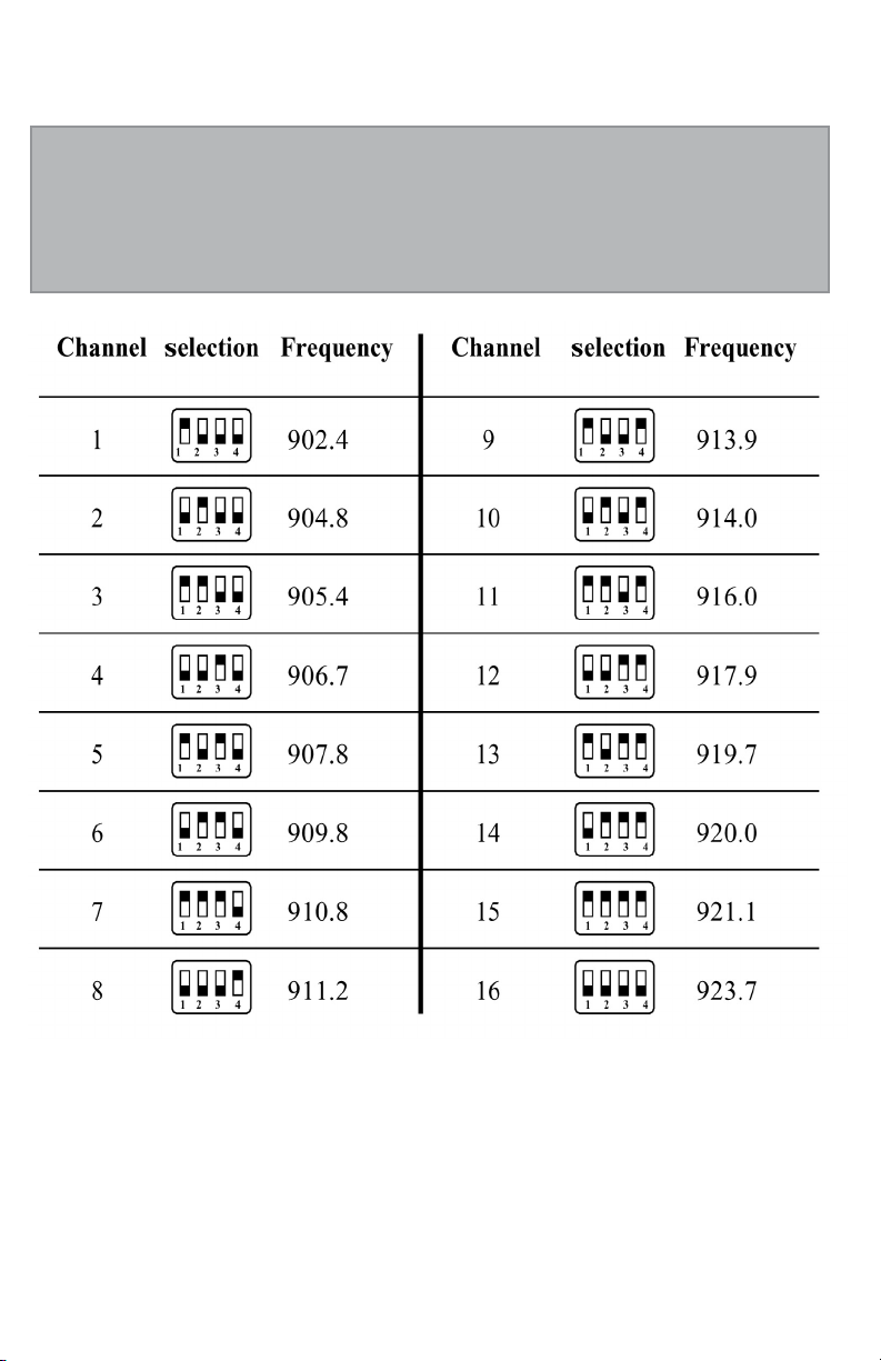
MRX-16 DIP-Switch
Frequency Selection Chart
Frequency Plan: 902.4MHz-923.7MHz (16 Channels) U.S.
16
Page 17

SPECIFICATIONS
MRX-16 System
Frequency Response 50Hz–16kHz (-3dB)
Dynamic Range 120dB
Oscillating System Phase Lock Loop (PLL)
Total Harmonic Distortion (THD) <0.8%
RF Carrier Frequency Range 902.40MHz–923.70MHz
Modulation FM (F3E), +/-30KHz normal
Operating Range Up to 250 feet (typical, depending on site conditions)
MRX-16 Receiver
Controls Audio Level, Power ON/MUTE/OFF
Frequency Select DIP-switches, ASCTM IR sync button
Connectors Unbalanced ¼”, DC Adapter input jack
LED Indicators
LED, IR Sync LED
Antenna ¼ wave, permanently attached
Signal-to-Noise Ratio > 105dB (w/AC/DC power supply)
Receiver Sensitivity -110dBm nominal, 12dB SINAD
Squelch Sensitivity -95dBm (normal)
Output Impedance 2.0KΩ
Power Consumption DC: 1.5V.95mA
Battery One AA alkaline or NiMH
Battery Life Up to 8 hours
Dimensions 2.4” W x 4.7” D x 0.9” H (6.1 cm x 12.0 cm x 2.3 cm)
Weight (w/o batteries) 2.3 oz (65.2g)
Housing Construction ABS Plastic
MT-16A/R Instrument Transmitters
RF Power Out 25mW nominal, 50mW maximum
Harmonic & spurious emissions -50dB
Controls Power ON/OFF, 15dB Attenuation Pad select switch
LED Indicators Power ON (Red-single ash), Low Battery (Red ashing)
Input Impedance 500KΩ
Power Consumption DC 1.5V/90mA
Battery One AAA alkaline or NiMH
Battery life Up to 8 hours
Antenna ¼ wave, permanently attached
Dimensions Dimensions MT-16A: 4.5” W x 2.0” D x 1.0” H
(11.43 cm x 5.08 cm x 2.54 cm)
Dimensions MT-16R: 3.5” W x 2.5” D x 1.0” H (8.9 cm x 6.35 cm x 2.54 cm)
Weight (w/o batteries) MT-16A: 1.2 oz (34 g), MT-16R: 1.1 oz (31.2 g)
Housing Construction ABS Plastic
MH-16 Saxophone (Horn) Instrument Transmitter
RF Power Out 25mW nominal, 50mW maximum
Harmonic & spurious emissions -50dB
Controls Power ON/OFF, 15dB Attenuation Pad select switch
LED Indicators Power ON (Red-single ash), Low Battery (Red ashing)
Input Impedance 500KΩ
Power Consumption DC 1.5V/90mA
Battery One AAA alkaline or NiMH
Battery life Up to 8 hours
Antenna ¼ wave, permanently attached
Dimensions 8.5” W x 2.25” D x 1.0” H (21.6 cm x 5. 8 cm x 2.54 cm)
Weight (w/o batteries) 2.1 oz (59.6 g)
Housing Construction ABS Plastic
LK-16 Snap-On Transmitter
RF Power Out 25mW nominal, 50mW maximum
Harmonic & spurious emissions -50dB
Controls Power ON/OFF
LED Indicators Power ON (Red-single ash), Low Battery (Red ashing)
Input Impedance 5KΩ
Power Consumption DC 1.5V/90mA
Battery One AAA alkaline or NiMH
Battery life Up to 8 hours
Antenna ¼ wave, permanently attached
Dimensions Dimensions 4.25” W x 1.2” D x 1.0” H (10.8 cm x 3.05 cm x
2.54 cm)
Weight (w/o batteries) 1.5 oz (42.5 g)
Housing Construction ABS Plastic
WH-16 Head-Worn Transmitter
RF Power Out 25mW nominal, 50mW maximum
Harmonic & spurious emissions -50dB
Controls Power ON/OFF
LED Indicators Power ON (Red-single ash), Low Battery (Red ashing)
Input Impedance 5KΩ
Power Consumption DC 1.5V/90mA
Battery One AAA alkaline or NiMH
Battery life Up to 8 hours
Antenna ¼ wave, permanently attached
Dimensions Dimensions (w/Mic) 6” W x 7” D x 2.5” H (15.3 cm x 17.8 cm x
6.4 cm)
Weight (w/o batteries) 2.1 oz (59.6 g)
Housing Construction ABS Plastic
Specications subject to change at any time without prior notice for purposes of product improvement
Power ON (Red-single ash), Low Battery (Red ashing), RF Signal
17
Page 18

SERVICE FOR YOUR NADY AUDIO PRODUCT
Please do not return our product to the store where it was
purchased. Nady Systems, Inc. assumes the responsibility of
keeping you a satised customer.
DO NOT ATTEMPT TO SERVICE THIS UNIT YOURSELF
AS IT CAN BE DANGEROUS AND WILL ALSO VOID THE
WARRANTY.
If factory service is required, please call our Service
Department at 510/652-2411 or e-mail [email protected]
for a return authorization (RA) number. Make sure the RA
number is clearly marked on the outside of the package.
If unit is past the One Year Warranty, The Nady Service
Department will provide a quote for service or replacement.
Please make sure a cashier’s check or money order is
enclosed (if not prepaid with credit card) with the shipment
to Nady.
If unit is within the One Year Warranty from purchase, please
check Warranty terms for further instruction before sending
in unit.
Nady Systems will not repair nor be held responsible for any
units sent without proper identication and return address or
RA number clearly marked on the package.
For service, please ship units prepaid to:
Nady Systems, Inc., Service Department,
6701 Shellmound St., Emeryville, CA 94608
18
Page 19

ONE YEAR WARRANTY
Nady Systems, Inc. warrants to the original consumer purchaser that
your unit is free from any defects in material or workmanship for a
period of one year from the date of purchase. If any such defect is
discovered within the warranty period, Nady Systems, Inc. will repair
or replace the unit free of charge, subject to verication of the defect
or malfunction upon delivery or shipping prepaid to Nady Systems.
This warranty does not apply to defects or physical damage resulting
from abuse, neglect, accident, improper repair, alteration, or
unreasonable use of the unit resulting in cracked or broken cases or
parts, or units damaged by excessive heat, and does not apply to
batteries or damage caused by leaking batteries. This warranty does
not cover nish or appearance items nor items damaged in shipment
en route to Nady Systems, Inc. for repair. You must include proof of
date and place of purchase (i.e., photocopy of your bill of sale) or we
cannot be responsible for repairs or replacement. See Service section
for further instructions.
Any applicable implied warranties including warranties of
merchantability and tness are hereby limited to one year from
date of purchase. Consequential or incidental damages resulting
from a breach of any applicable express or implied warranties are
hereby excluded. This warranty is in lieu of all other agreements
and warranties, general or special, express or implied and no
representative or person is authorized to assume for us any other
liability in connection with the sale or use of this Nady Systems’
product.
Note: Some states do not allow limitations on how long implied warranties last and do not allow
exclusion of incidental or consequential damages, so the above limitations and exclusions may not
apply to you. This warranty gives you specic legal rights, and you may also have other rights
which may vary from state to state.
International Customers: For service, please contact the NADY AUDIO distributor in your
country via the dealer from whom you purchased this product.
www.nady.com
6701 Shellmound Street | Emeryville, CA USA 94608
T 510.652.2411 | F 510.652.5075
19
Page 20

www.nady.com
6701 Shellmound Street | Emeryville, CA USA 94608
T 510.652.2411 | F 510.652.5075
 Loading...