

Page 1
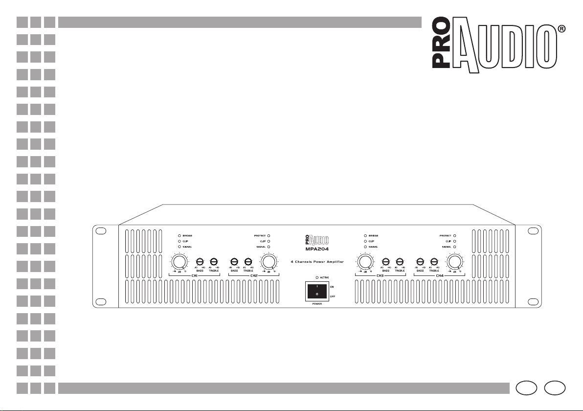
MPA204
Manuale
User Manual
©2007 Music & Lights s.r.l. - Italy - www.musiclightsitaly.com - [email protected]
I GB
Page 2

Page 3

Introduzione
Vi siamo grati per aver scelto un prodotto ProAudio.
L’amplificatore MPA204 di ProAudio, rappresenta una nuova era
nel settore dell’amplificazione di qualità a costi contenuti.
Questo modello incorpora un principio di design “tried and true”
(testato e provato) insieme a caratteristiche innovative.
I moderni amplificatori professionali sono sofisticati pezzi di
ingegneria capaci di produrre estremi livelli di potenza.
Devono essere installati ed usati con cura ed attenzione per
poter conservare la principale peculiarità contemplata in fase di
progettazione: la massima affidabilità nel tempo.
L’MPA204 possiede un numero di caratteristiche e possibilità che
richiedono qualche nozione per poter trarre il massimo vantaggio
dal suo uso.
Vi invitiamo a dedicare il tempo necessario per studiare questo
manuale al fine di ottenere il massimo vantaggio dall’uso del
vostro amplificatore.
Contenuto dell’imballo:
1 x Amplificatore MPA204
1 x Cavo di alimentazione
1 x Manuale utente
Indice
Sicurezza
Layout - Descrizione Pannelli
Alimentazione e accensione
Specifiche tecniche
Cavi e connettori
Connessioni (modo 4 canali)
(modo stereo + sub)
(modo bridge stereo)
(modo 4 canali via BUS IN)
Brevi cenni di acustica
MPA204
1
2
3
4
5
6
7
8
9
10
I
Le informazioni riportate in questo manuale sono state attentamente controllate.
Music & Lights non si assume, tuttavia, responsabilità derivanti da eventuali inesattezze.
Tutte le specifiche possono variare senza alcuna notifica.
FP- 05 /12/07 - Rev01 - ©2007 Music & Lights s.r.l. - Italy - www.musiclightsitaly.com
3
Page 4

I
PRECAUZIONI
• Leggere attentamente tutta la documentazione prima di far funzionare l’unità e conservarla in un luogo sicuro per un riferimento futuro.
• Non usare l’unità vicino all’acqua o comunque in zone umide.
• Pulire esclusivamente tramite l’uso di un panno asciutto.
• Non ostruire in alcun modo le griglie di areazione dell’unità.
• Non installare l’unità vicino a fonti di calore di qualsiasi genere. L’unità deve essere installata in modo che goda di una adeguata ventilazione, almeno a 50 cm dalle
superfici adiacenti.
• Controllare che il voltaggio della rete sia identico a quello stampato sul retro dell’unità. Danni causati da connessione a voltaggi impropri, non sono coperti da alcuna
garanzia.
• Qualora la spina del cavo in dotazione non corrispondesse con la presa a muro da utilizzare per l’alimentazione, consultare un tecnico qualicato per risolvere il
problema. In particolare controllare che l’impianto elettrico sia dotato di una efficiente messa a terra e controllare che la presa a muro e la spina del cavo di
alimentazione siano perfettamente compatibili.
• Impiegare l’unità con la presa terra sempre connessa alla terra del sistema elettrico.
• Proteggere il cavo di alimentazione e le sue spine di connessione, da qualsiasi contatto involontario: calpestamenti, urti, abrasioni ecc..
• Scollegare l’unità dall’alimentazione durante temporali e se non utilizzata per lungo tempo.
• Il collegamento dell’uscita, con l’unità in modo bridge, ad un oscilloscopio è vietata: ciò può causare danni all’unità ed ad altre apparecchiature.
• Rivolgersi a personale qualicato per qualsiasi tipo di riparazione e/o controllo come ad esempio: cavo di alimentazione danneggiato, liquido penetrato nell’unità,
oggetti penetrati nell’unità, l’unità è stata esposta a pioggia o eccessiva umidità, l’unità non opera normalmente, l’unità ha subito traumi di qualsiasi genere.
• Il livello di uscita dell’amplicatore non deve mai superare la sensibilità segnata.
• Non collegare l’uscita di un amplicatore nell’entrata di un altro. Non collegare in serie o in parallelo le uscite di un amplicatore con quelle di un altro.
• Nell’allestimento del sistema, la potenza di uscita di un amplicatore deve essere dal 50% al 100% più grande di quella di funzionamento del diusore.
• Assicurarsi che il segnale sia connesso correttamente all’entrata dell’amplicatore e che esso sia nella giusta modalità di funzionamento.
• Spegnere l’amplicatore prima di disconnettere il cavo di alimentazione dalla rete.
• Pulire il ltro della polvere ogni 15 giorni.
MPA204
ATTENZIONE! Prima di eettuare qualsiasi operazione con l’unità, leggere con attenzione questo manuale:
contiene informazioni importanti riguardo l’installazione, l’uso e la manutenzione dell’unità.
PER RIDURRE IL RISCHIO DI SHOCK ELETTRICO NON RIMUOVERE LO CHASSIS O IL PANNELLO POSTERIORE
RIVOLGERSI AD UN PERSONALE QUALIFICATO - EVITARE DI ESPORRE L’UNITA’ ALLA PIOGGIA O LIQUIDI
» SICUREZZA
IMPORTANTE! Settaggi e funzioni non contemplate da questo manuale,
se applicati, potrebbero causare danni gravi a cose o persone.
Per qualsiasi necessità si prega di contattare il nostro ufficio tecnico:
tel. +39 0771 72190 fax +39 0771 721955 - [email protected]
FP- 05 /12/07 - Rev01 - ©2007 Music & Lights s.r.l. - Italy - www.musiclightsitaly.com
4
Page 5
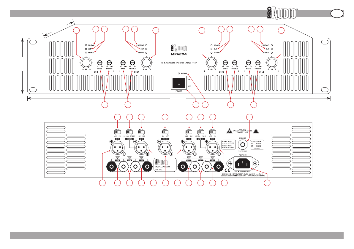
» LAYOUT - DESCRIZIONE PANNELLI
MPA204
I
89 mm
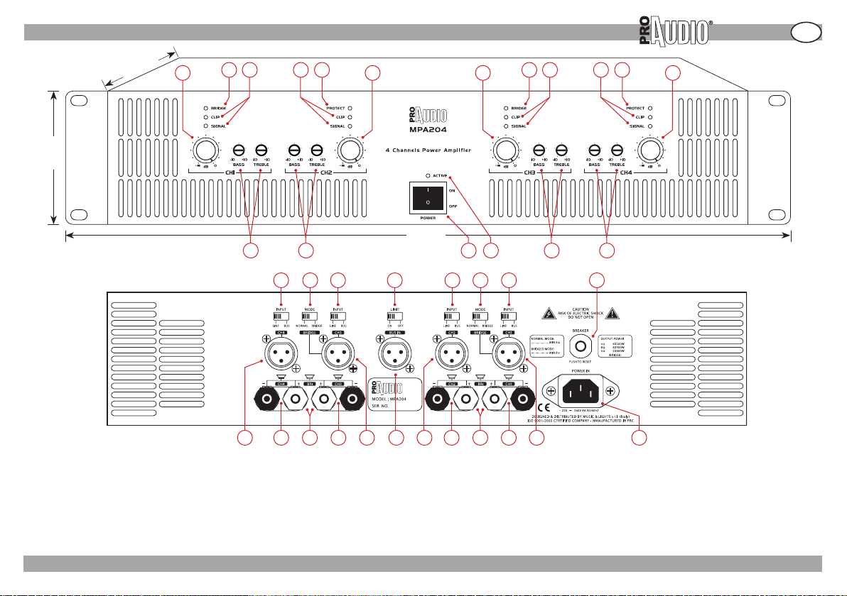
1. Livello CH1
2. Bridge CH1/CH2
3. Spie clip e segnale CH1
4. Spie clip e segnale CH2
5. Spia protezione CH1/
CH2
6. Livello CH2
375 mm
1
7. Livello CH3
8. Bridge CH3/CH4
9. Spie clip e segnale CH3
10. Spie clip e segnale CH4
11. Spia protezione CH3/CH4
12. Livello CH4
2 3 4 5
13
14 15 16 17 18
6 7
483 mm
8 9 10 11
19 20 21 22 23 24 25 26
28 29 3027 31 32 33 34 35 36 37 38
13. Alti-bassi CH1
14. Alti-bassi CH2
15. Interruttore di accensione
16. Spia acceso/spento.
17. Alti-bassi CH3
18. Alti-bassi CH4
19. Interruttore input CH4
20. Interr. modo CH3/CH4
21. Interruttore input CH3
22. Interruttore limiter
23. Interruttore input CH2
24. Interr. modo CH1/CH2
25. Interruttore input CH1
26. Tasto di reset
27. Input CH4
28. Output CH4
29. Output bridge 2
30. Output CH3
FP- 05 /12/07 - Rev01 - ©2007 Music & Lights s.r.l. - Italy - www.musiclightsitaly.com
12
31. Input CH3/Bridge CH3/CH4
32. Input bus
33. Input CH2
34. Output CH2
35. Output bridge 1
36. Output CH1
37. Input CH1/Bridge CH1/CH2
38. Presa di alimentazione IEC
5
Page 6

I
MPA204
» ALIMENTAZIONE E ACCENSIONE
Alimentazione.
Inserire il cavo di alimentazione incluso alla presa IEC
dell’unità e quindi alla presa di alimentazione dell’impianto
elettrico.
Attenzione! Abbiate cura di non disabilitare il pin di messa
a terra della spina inclusa usando un adattatore improprio o
attraverso altri metodi.
L’unità deve operare con una tensione che non superi il 10%
e non cali del 15% rispetto al voltaggio specico dell’unità
e all’interno della frequenza richiesta (dati specificati
sul pannello posteriore dell’unità). Se non si è sicuri del
voltaggio dell’impianto elettrico da utilizzare, rivolgersi ad
un tecnico qualificato.
Accensione.
Usare questa procedura per accendere l’unità:
1. Posizionare sul minimo il controllo di livello della
sorgente sonora.
2. Posizionare sul minimo i controlli di livello dell’unità.
3. Accendere l’unità tramite il tasto “power” (la spia
luminosa posta sopra il tasto dovrebbe illuminarsi).
4. Posizionare il controllo del volume della sorgente sonora
ad un livello ottimale.
5. Agire sui controlli di livello dell’unità fino a raggiungere il
volume necessario.
6. Riportare il livello della sorgente sonora al suo range
normale.
FP- 05 /12/07 - Rev01 - ©2007 Music & Lights s.r.l. - Italy - www.musiclightsitaly.com
6
Page 7
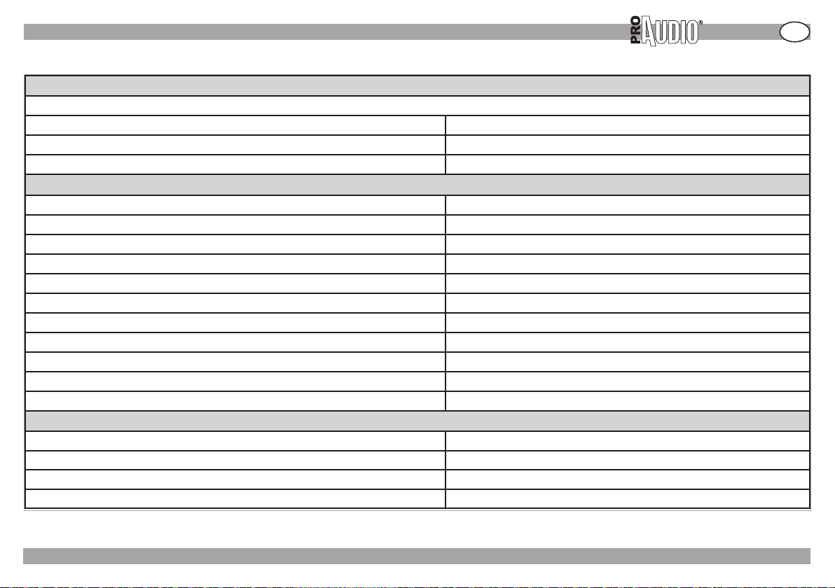
» SPECIFICHE TECNICHE
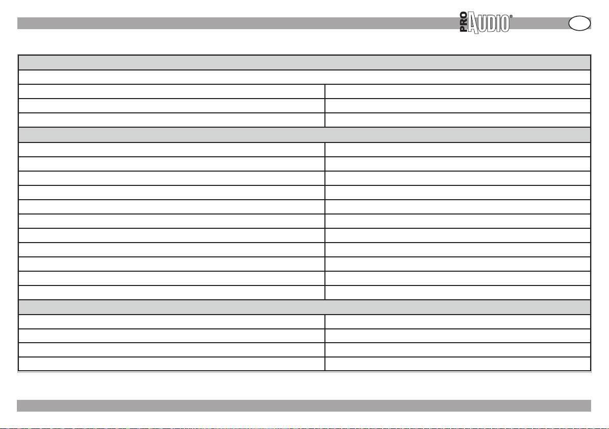
Potenza minima garantita
1 kHz with 0.5% THD
4-Channel, 8 ohms 4x200W
4-Channel, 4 ohms 4x300W
Bridge-stereo, 8 ohms 2x600W
Performance
Sensitivity (volts RMS) for full rated power at 8 ohms 0.775V
Frequency Response (at 1 watt, 20Hz - 25 kHz) +0dB, -0.5dB
Phase Response (at 1 watt , 20Hz to 20 kHz) +10° ,-20°
Signal to Noise Ratio below rated power A-weighted ≥100dB
Intermodulation Distortion (IMD) 60 Hz and 7 kHz at 4:1,from full rated output to -35 dB ≤ 0.1%
Damping Factor (8 ohm): 20 Hz to 400 Hz ≥200
Input Impedance (nominally balanced, nominally unbalanced) 20 kilohms, 10 kilohms
Load Impedance (Note: Safe with all types of loads) 4-Channel 4-8 ohms
Load Impedance (Note: Safe with all types of loads) Bridge-Stereo 8 ohms
AC Line Voltage and Frequency Congurations Available ( ± 10%) ~220-240 V and 50/60 Hz
AC Line Current (both amplifiers draw no more than 90 watts at idle) 8A
Construction
Ventilation Flow-through ventilation from front to back
Cooling Proportional speed fan
Dimensions H x W x D: 89mm 483mm 496mm
Net Weight/Shipping Weight 16kg/18kg
MPA204
I
FP- 05 /12/07 - Rev01 - ©2007 Music & Lights s.r.l. - Italy - www.musiclightsitaly.com
7
Page 8
I
MPA204
CAVI E CONNETTORI
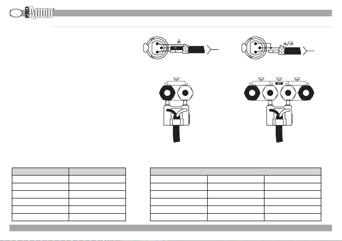
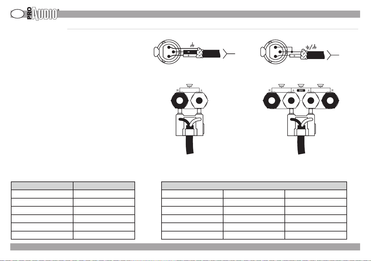
Cavi e connettori di input.
Si raccomanda l’uso di cablaggi professionali con linee
bilanciate e cavi e connettori standard 22-24.
A seconda dell’input usato, dovrebbero essere adoperati:
connettori XLR maschi, connettori jack TRS phone
o terminali a forcella.
Possono essere usate anche linee non bilanciate ma
queste potrebbero generare rumore di fondo, specialmente
nel caso i cavi siano particolarmente lunghi.
Le prese input non usate per l’ingresso di segnale audio
possono essere usate per creare collegamenti a cascata
con altri componenti.
Cavi e connettori di output.
Si raccomanda l’uso di cavi e connettori professionali a 2 o
4 conduttori. E’ possibile usare connettori speakon a 2 o 4
poli, prese a banana o connettori a forcella avendo cura , in
questo caso, di coprire o comunque isolare le parti esposte
dei connettori per prevenire il richio di cortocircuiti.
» CAVI E CONNETTORI
GND
1
2
3
INPUT
connettore bilanciato connettore non bilanciato
SOURCE
1
3
INPUT
SHIELD
2
SOURCE
Lo schema sottostante rappresenta un aiuto alla scelta del
cavo più adatto in base alla distanza tra l’amplicatore e i
diusori.
DISTANZA DIMENSIONE DEL CAVO Ø
fino a 7 mt 16 AWG (1.290 mm)
da 8 a 12 mt 14 AWG (1.630 mm)
da 13 a 18 mt 12AWG (2.050 mm)
da 19 a 30 mt 10 AWG (2.590 mm)
da 31 a 46 mt 8 AWG (3.260 mm)
da 47 a 76 mt 6 AWG (4.110 mm)
FP- 05 /12/07 - Rev01 - ©2007 Music & Lights s.r.l. - Italy - www.musiclightsitaly.com
cablaggio in modalità normale cablaggio in modalità bridge
ASSEGNAZIONE OUTPUT
OUTPUT 1 CH1+ (positivo) CH1- (negativo)
OUTPUT 2 CH2+ (positivo) CH2- (negativo)
BRIDGE 1 CH1+ (positivo) CH2+ (negativo)
OUTPUT 3 CH3+ (positivo) CH3- (negativo)
OUTPUT 4 CH4+ (positivo) CH4- (negativo)
BRIDGE 2 CH3+ (positivo) CH4+ (negativo)
8
Page 9
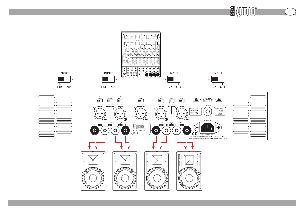
» CONNESSIONI
MODO 4 CANALI
MIXER
MPA204
I
DIFFUSORI
FP- 05 /12/07 - Rev01 - ©2007 Music & Lights s.r.l. - Italy - www.musiclightsitaly.com
9
Page 10
I
MPA204
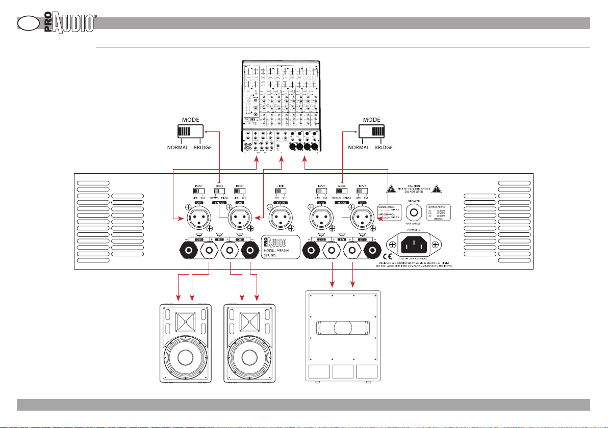
» CONNESSIONI
MODO STEREO + SUB
MIXER
DIFFUSORI (FULL RANGE)
FP- 05 /12/07 - Rev01 - ©2007 Music & Lights s.r.l. - Italy - www.musiclightsitaly.com
SUBWOOFER
10
Page 11
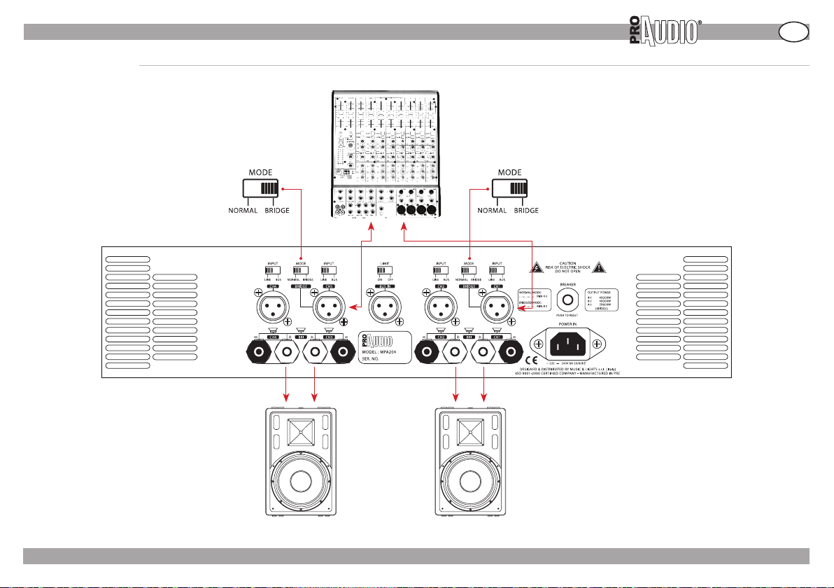
» CONNESSIONI
MODO BRIDGE STEREO
MIXER
MPA204
I
DIFFUSORI (FULL RANGE)
FP- 05 /12/07 - Rev01 - ©2007 Music & Lights s.r.l. - Italy - www.musiclightsitaly.com
11
Page 12
I
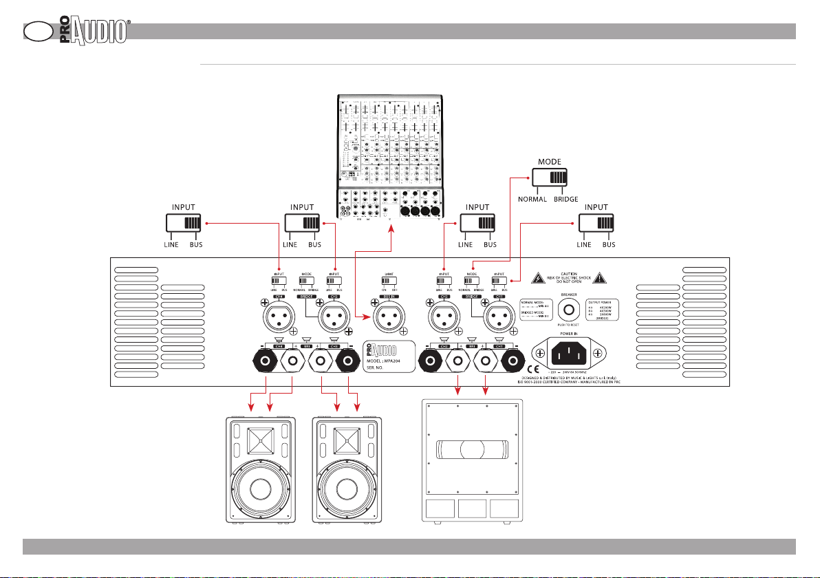
MODO 4 CANALI CON INGRESSO BUS
In caso di segnale di input dinamico per lunghi periodi di
tempo, posizionare il tasto “limit” in posizione “ON” al fine di
evitare seri problemi di clipping.
MPA204
» CONNESSIONI
MIXER
SUBWOOFERDIFFUSORI
FP- 05 /12/07 - Rev01 - ©2007 Music & Lights s.r.l. - Italy - www.musiclightsitaly.com
12
Page 13

» BREVI CENNI DI ACUSTICA
BREVI CENNI DI ACUSTICA
La diusione del suono in un ambiente ha lo scopo di soddisfare l’ascolto da parte di un certo
numero di persone ed è legata a diversi fattori dipendenti dall’ambiente stesso (forma della
sala, volume, ecc...), dal numero e dalla posizione degli ascoltatori, dalla natura della sorgente
sonora (esecuzioni musicali o parlato, riprodotti da registrazione o dal vivo) e dal livello di
rumore presente nell’ambiente.
EFFICIENZA
La pressione sonora di un diusore (SPL misurata in dB) dipende da tre fattori: la sua efficien-
za, le sue dimensioni ed il suo utilizzo in combinazione con altri diusori. L’ecienza, cioè la
quantità di energia prodotta dall’amplificatore trasformata in suono, determina il volume che
si può ottenere da un amplicatore di una data potenza.
Diusori molto ecienti, possono far sì che un amplicatore da 50W produca maggior volume di uno da 100W usato con diusori meno ecienti.
IMPEDENZA
Una delle caratteristiche elettriche di un diusore è l’impedenza ( la resistenza opposta alla
corrente alternata). Sia la resistenza che l’impedenza si misurano in Ohm; l’impedenza varia
al variare della frequenza quindi ne consegue che le diverse frequenze possono essere rese
con un SPL diverso. Un diusore con impedenza superiore a quella minima di funzionamento
del nale può essere utilizzata a scapito della potenza erogata, mentre è bene evitare collegamenti con diusori che hanno impedenza minore di quella minima di lavoro del nale di
potenza. Usando sistemi più complessi (ad esempio più speakers collegati allo stesso nale)
bisogna fare in modo che il valore totale dell’impedenza degli altoparlanti sia corrispondente
a quella minima di funzionamento del amplificatore. Possiamo avere due tipi di collegamento:
in serie o in parallelo.
Collegare in serie due altoparlanti significa unire un terminale positivo ed uno negativo dei
due e collegare all’amplificatore i rimanenti due terminali rimasti scollegati. I loro valori si sommano: per esempio, due altoparlanti da 8 Ohm in serie danno 16 Ohm.
Quando gli altoparlanti sono collegati in parallelo, i terminali dello stesso segno sono uniti
tra loro. Per ottenere il valore totale bisogna utilizzare una formula, indicando con R1 ed R2 i
valori di due altoparlanti, ed eseguire : (R1 x R2) / (R1 + R2). Con due altoparlanti da 8 Ohm, per
esempio, avremo: (8x8)/(8+8) = 64/16 = 4 Ohm.
In pratica collegando due altoparlanti uguali in parallelo il valore si dimezza. La lunghezza dei
cavi di collegamento deve essere ridotta al minimo necessario.
COME SCEGLIERE L’AMPLIFICATORE:
La potenza di lungo termine AES, rappresenta la potenza termica dissipabile dal diusore o
dai singoli altoparlanti, viene misurata secondo lo standard AES, che prevede un test di 2 ore
con segnale pink noise, fattore di cresta 2 ; la potenza viene determinata dalla tensione RMS
al quadrato divisa per l’impedenza minima del diusore o del singolo altoparlante.
La potenza dell’amplicatore consigliato non viene misurata, ma è pari al doppio della po-
tenza AES e tiene conto delle capacità dinamiche degli altoparlanti di sopportare picchi di
potenza per brevi istanti di tempo. Il valore fornito corrisponde alla potenza RMS che l’amplificatore deve avere per fornire il segnale di test ( pink noise con fattore di cresta 2) usato per
misurare la potenza AES.
FP- 05 /12/07 - Rev01 - ©2007 Music & Lights s.r.l. - Italy - www.musiclightsitaly.com
MPA204
Un amplificatore con tale potenza, se usato con segnali musicali con fattore di cresta
maggiore o uguale a 6dB, permette di ottenere il massimo delle prestazioni del diusore, erogando una potenza di lungo periodo non superiore a quella AES del diusore.
Se, viceversa, si usano segnali musicali molto compressi o il volume viene alzato fino al
punto da spingere fortemente in clipping l’amplicatore, allora, la potenza eettiva di
lungo periodo erogata, tende a raggiungere o addirittura superare quella RMS dell’amplificatore, danneggiando in modo irreparabile gli altoparlanti. Con questo tipo di se-
gnale è consigliabile usare un amplicatore con potenza RMS pari alla potenza AES del
diusore, facendo comunque attenzione a non fornire un segnale di ampiezza tale da
portare troppo spesso in clipping l’amplificatore. La potenza di breve termine IEC268-5
è la potenza che il diusore può sopportare per un brevissimo intervallo di tempo. Corrisponde a 4 volte la potenza AES e viene calcolata in base alla massima tensione di picco
che l’amplicatore consigliato può fornire al diusore. Le capacità in termine di SPL nei
transistori del segnale musicale, sono eettivamente corrispondenti a tale valore; quindi
il dato di SPL max fornito nella tabella delle specifiche tecniche viene calcolato in base a
tale valore di potenza.
Attenzione: il dato di potenza che eettivamente corrisponde alle capacità termiche
del diusore di dissipare potenza elettrica per lungo periodo è quella AES. Tutti gli altri
dati si riferiscono a “capacità transitorie” del diusore di accettare potenze correlate con
la natura del segnale audio che sono destinate a riprodurre.
GLOSSARIO
SPL: Il livello di pressione sonora (SPL) o livello sonoro Lp è una misura logaritmica della
pressione sonora efficace di un’onda meccanica (sonora) rispetto ad una sorgente sonora
di riferimento. Viene misurata in decibel sonori (simbolo “dbSPL”).
AES: L’AES, Audio Engineering Society, è forse la più prestigiosa associazione internazio-
nale in campo audio.
E’ l’unica associazione a livello mondiale che si occupa di audio sotto tutti i punti di vista,
dall’acustica all’elaborazione dei segnali, dall’elettronica per l’audio ai metodi di misura.
Per questo suo ruolo interdisciplinare è il naturale collettore di tutte le esperienze di
natura professionale e di studio di oltre duecento aziende e centri di ricerca (le sustaining members), periodicamente documentate sull’organo ufficiale dell’associazione: il
Journal.
Sempre per lo stesso motivo, molti standard tecnici subiscono continue variazioni sotto
l’egida dell’AES; in parecchi casi le indicazioni date dalla commissione di standardizzazione sono diventate linee guida per gli standard veri e propri.
Tra i suoi soci figurano ricercatori universitari, accreditati professionisti nonché i grandi
fondatori dell’audio; un nome per tutti, ad esempio: Ray Dolby.
RMS: Root-mean-square (rms). La sigla si riferisce al più comune metodo matematico
atto a denire l’eettivo voltaggio o corrente di un’onda di corrente alternata. Il nome
deriva dal fatto che il valore ottenuto è la radice quadrata (square root) della media arit-
metica dei quadrati dei valori.
I
13
Page 14
Notes/comments:
Page 15

Introduction
Vi siamo grati per aver scelto un prodotto ProAudio.
L’amplificatore MPA204 di ProAudio, rappresenta una nuova era
nel settore dell’amplificazione di qualità a costi contenuti.
Questo modello incorpora un principio di design “tried and true”
(testato e provato) insieme a caratteristiche innovative.
I moderni amplificatori professionali sono sofisticati pezzi di
ingegneria capaci di produrre estremi livelli di potenza.
Devono essere installati ed usati con cura ed attenzione per
poter conservare la principale peculiarità contemplata in fase di
progettazione: la massima affidabilità nel tempo.
L’MPA204 possiede un numero di caratteristiche e possibilità che
richiedono qualche nozione per poter trarre il massimo vantaggio
dal suo uso.
Vi invitiamo a dedicare il tempo necessario per studiare questo
manuale al fine di ottenere il massimo vantaggio dall’uso del
vostro amplificatore.
Packing list:
1 x MPA204 amplifiers
1 x AC power cordset
1 x User manual
MPA204
Index
Safety
Layout - Panels Description
AC mains connection - Startup
Technical specifications
Wires and connectors
Connections (4 channels mode)
(stereo + sub mode)
(bridge stereo mode)
(4 Channel Mode (BUS IN mode)
Brief notes on acoustic
GB
1
2
3
4
5
6
7
8
9
10
The informations provided in this manual have been carefully controlled.
However, Music & Lights is not responsible for any possible inaccuracy.
Design and specifications are subject to change without notice.
FP- 05 /12/07 - Rev01 - ©2007 Music & Lights s.r.l. - Italy - www.musiclightsitaly.com
1
Page 16

GB
WARNING! Please read the instruction carefully which includes important information about the installation, usage and maintenance.
TO PREVENT ELECTRIC SHOCK DO NOT REMOVE TOP OR BOTTOM COVERS. DO NOT EXPOSE THIS EQUIPMENT TO RAIN OR MOISTURE
PRECAUTIONS
• Read all documentation before using your equipment. Retain all documentation for further reference.
• Do not use this apparatus near water.
• Clean only with a dry cloth.
• Do not block any ventilation openings. Install in accordance with the manufacturers instructions.
• Do not install near any heat sources such as radiators, heat registers, stoves, or other apparatus that produce heat.
• Mains voltage must be correct and the same as that printed on the rear of the unit. Damage caused by connection to improper AC voltage is not covered by any
warranty.
• Do not defeat the safety purpose of the polarized or grounding-type plug. A polarized plug has two blades with one wider than the other. A grounding-type plug has
two blades and a third grounding prong. The wide blade or the third prong is provided for your safety. If the provided plug does not fit into your outlet,
consult an electrician for replacement of the obsolete outlet.
• Always operate the unit with the AC ground wire connected to the electrical system ground.
• Protect the power cord from being walked on or pinched, particularly at plugs, convenience receptacles, and the point where they exit from the apparatus.
• Unplug this apparatus during lightning storms or when unused for long periods of time.
• Linking an output to an oscillograph - when in “bridge” mode - is prohibited or it would cause damage to the amplier and to the equipment.
• Refer all servicing to qualied service personnel. Servicing is required when the apparatus has been damaged in any way, such as powersupply cord or plug is damaged,
liquid has been spilled or objects have fallen into the apparatus, the apparatus has been exposed to rain or moisture, does not operate normally, or has been dropped.
• The output level of the amplier shall not exceed the marked sensitivity.
• Do not link the output of any amplier channel back into another channel ‘s input. Do not parallel or series connect an amplier’s output with any other amplier’s
output.
• In system’s setup, amplier’s output power must be from 50% up to100% greater than the loudspeaker’s rated power.
• Make sure that the signal is correctly connected to the amplier’s input channel and according to the proper input mode.
• Please turn o the power switch before pulling o the power cord, before managing signal cables or before selecting the input mode switch.
• Please clean the dust lter every 15 days.
MPA204
NO USER SERVICEABLE PARTS INSIDE - REFER SERVICING TO QUALIFIED SERVICE PERSONNEL.
» SAFETY
IMPORTANT DIRECTION! :Other control functions and adjustments not present in
this user’s manual, might cause damages to things and persons.
For further information please contact our Service Center:
tel. +39 0771 72190 fax +39 0771 721955 [email protected]
©2007 Music & Lights s.r.l. - Italy - www.musiclightsitaly.com - FP- 05 /12/07 - Rev01
2
Page 17
» LAYOUT - PANELS DESCRIPTION
MPA204
GB
89 mm
1. CH1 Level Control
2. CH1&CH2 Bridge
3. CH1 Signal & Clip
4. CH2 Signal & Clip
5. CH1 & CH2 Protect
6. CH2 Level Control
375 mm
1
7. CH3 Level Control
8. CH3 & CH4 Bridge
9. CH3 Signal &Clip
10. CH4 Signal &Clip
11. CH3 & CH4 Protect
12. CH4 Level Control
2 3 4 5
13
14 15 16 17 18
6 7
483 mm
8 9 10 11
19 20 21 22 23 24 25 26
28 29 3027 31 32 33 34 35 36 37 38
13. CH1 Bass & Treble
14. CH2 Bass & Treble
15. Power Switch
16. Power Indicator
17. CH3 Bass & Treble
18. CH4 Bass & Treble
19. CH4 Input Switch
20. CH3&CH4 Mode Switch
21. CH3 Input Switch
22. Limiter Switch
23. CH2 Input Switch
24. CH1 & CH2 Mode Switch
25. CH1 Input Switch
26. Breaker
27. CH4 Input
28. CH4 output
29. Bridge2 Output
30. CH3 output
FP- 05 /12/07 - Rev01 - ©2007 Music & Lights s.r.l. - Italy - www.musiclightsitaly.com
12
31. CH3 input/Bridge CH3/CH4
32. Bus input
33. CH2 input
34. CH2 output
35. Bridge Output 1
36. CH1 output
37. CH1 input/Bridge CH1/CH2
38. IEC Power Cord Connector
3
Page 18

GB
MPA204
» AC MAINS CONNECTION - STARTUP
Connect to AC Mains.
Connect your amplifier to the AC mains power source
(power outlet) with the supplied AC power cordset. First,
connect the IEC end of the cordset to the IEC connector on
the amplifier; then, plug the other end of the cordset to
the AC mains.
WARNING: The third prong of this connector(ground)
is an important safety feature. Do not attempt to disable
this ground connection by using an adapter or other
methods.
Amplifiers don t create energy. The AC mains voltage and
current must be sufficient to deliver the power you expect.
You must operate your amplifier from an AC mains power
source with not more than a 10% variation above or a 15%
variation below the amplifier s specified line voltage
and within the specfied frequency requirements (indicated
on the amplifier s back panel label). If you are unsure of
the output voltage of your AC mains, please consult your
electrician.
Startup Procedure.
Use the following procedure when first turning on your
amplifier:
1. Turn down the level of your audio source.
2. Turn down the level controls of the amplifier.
3. Turn on the Power switch. The Power indicator should glow.
4. Turn up the level of your audio source to an optimum level.
5. Turn up the Level controls on the amplifier until the
desired loudness or power level is achieved.
6. Turn down the level of your audio source to its normal
range.
If you ever need to make any wiring or installation changes,
do not forget to disconnect the power cord.
©2007 Music & Lights s.r.l. - Italy - www.musiclightsitaly.com - FP- 05 /12/07 - Rev01
4
Page 19
» TECHNICAL SPECIFICATIONS
Minimum Guaranteed Power
1 kHz with 0.5% THD
4-Channel, 8 ohms 4x200W
4-Channel, 4 ohms 4x300W
Bridge-stereo, 8 ohms 2x600W
Performance
Sensitivity (volts RMS) for full rated power at 8 ohms 0.775V
Frequency Response (at 1 watt, 20Hz - 25 kHz) +0dB, -0.5dB
Phase Response (at 1 watt , 20Hz to 20 kHz) +10° ,-20°
Signal to Noise Ratio below rated power A-weighted ≥100dB
Intermodulation Distortion (IMD) 60 Hz and 7 kHz at 4:1,from full rated output to -35 dB ≤ 0.1%
Damping Factor (8 ohm): 20 Hz to 400 Hz ≥200
Input Impedance (nominally balanced, nominally unbalanced) 20 kilohms, 10 kilohms
Load Impedance (Note: Safe with all types of loads) 4-Channel 4-8 ohms
Load Impedance (Note: Safe with all types of loads) Bridge-Stereo 8 ohms
AC Line Voltage and Frequency Congurations Available ( ± 10%) ~220-240 V and 50/60 Hz
AC Line Current (both amplifiers draw no more than 90 watts at idle) 8A
Construction
Ventilation Flow-through ventilation from front to back
Cooling Proportional speed fan
Dimensions H x W x D: 89mm 483mm 496mm
Net Weight/Shipping Weight 16kg/18kg
MPA204
GB
FP- 05 /12/07 - Rev01 - ©2007 Music & Lights s.r.l. - Italy - www.musiclightsitaly.com
5
Page 20
GB
MPA204
WIRES AND CONNECTORS
Choose Input Wire and Connectors.
We recommends using pre-built or professionally
wired, balanced line (two-conductor plus shield), 22-24
gauge cables and connectors. Depending upon which
amplifier input you choose, you should use either 3-pin
male
XLR connectors, TRS phone connectors, or terminal forks
at the amplifier inputs. Unbalanced line may also be used
but may result in noise over long cable runs.
Note: Amplifier input connectors not used for audio signal
input may be used for daisy-chaining of the audio signal
to other components.
Choose Output Wire and Connectors.
We recommends using pre-built or professionally wired,
highquality, two- or four-conductor, heavy gauge speaker
wire and connectors. You may use two 4-pole Speakon
connectors or banana plugs, spade lugs, To prevent the
possibility of short-circuits, wrap or otherwise insulate
exposed loudspeaker cable connectors.
Using the guidelines below, select the appropriate size of
wire based on the distance from amplifier to speaker.
DISTANCE WIRE SIZE Ø
up to 7 mt 16 AWG (1.290 mm)
from 8 to 12 mt 14 AWG (1.630 mm)
from 13 to 18 mt 12AWG (2.050 mm)
from 19 to 30 mt 10 AWG (2.590 mm)
from 31 to 46 mt 8 AWG (3.260 mm)
from 47 to 76 mt 6 AWG (4.110 mm)
» WIRES AND CONNECTORS
GND
1
2
3
INPUT
Balanced Input
Connector Wiring
Normal Operation Wiring Bridged operation wiring
OUTPUT 1 CH1+ (positive) CH1- (negative)
OUTPUT 2 CH2+ (positive) CH2- (negative)
BRIDGE 1 CH1+ (positive) CH2+ (negative)
OUTPUT 3 CH3+ (positive) CH3- (negative)
OUTPUT 4 CH4+ (positive) CH4- (negative)
BRIDGE 2 CH3+ (positive) CH4+ (negative)
SOURCE
OUTPUT ASSIGNMENT
1
3
INPUT
SHIELD
2
Unbalanced Input
Connector Wiring
SOURCE
©2007 Music & Lights s.r.l. - Italy - www.musiclightsitaly.com - FP- 05 /12/07 - Rev01
6
Page 21
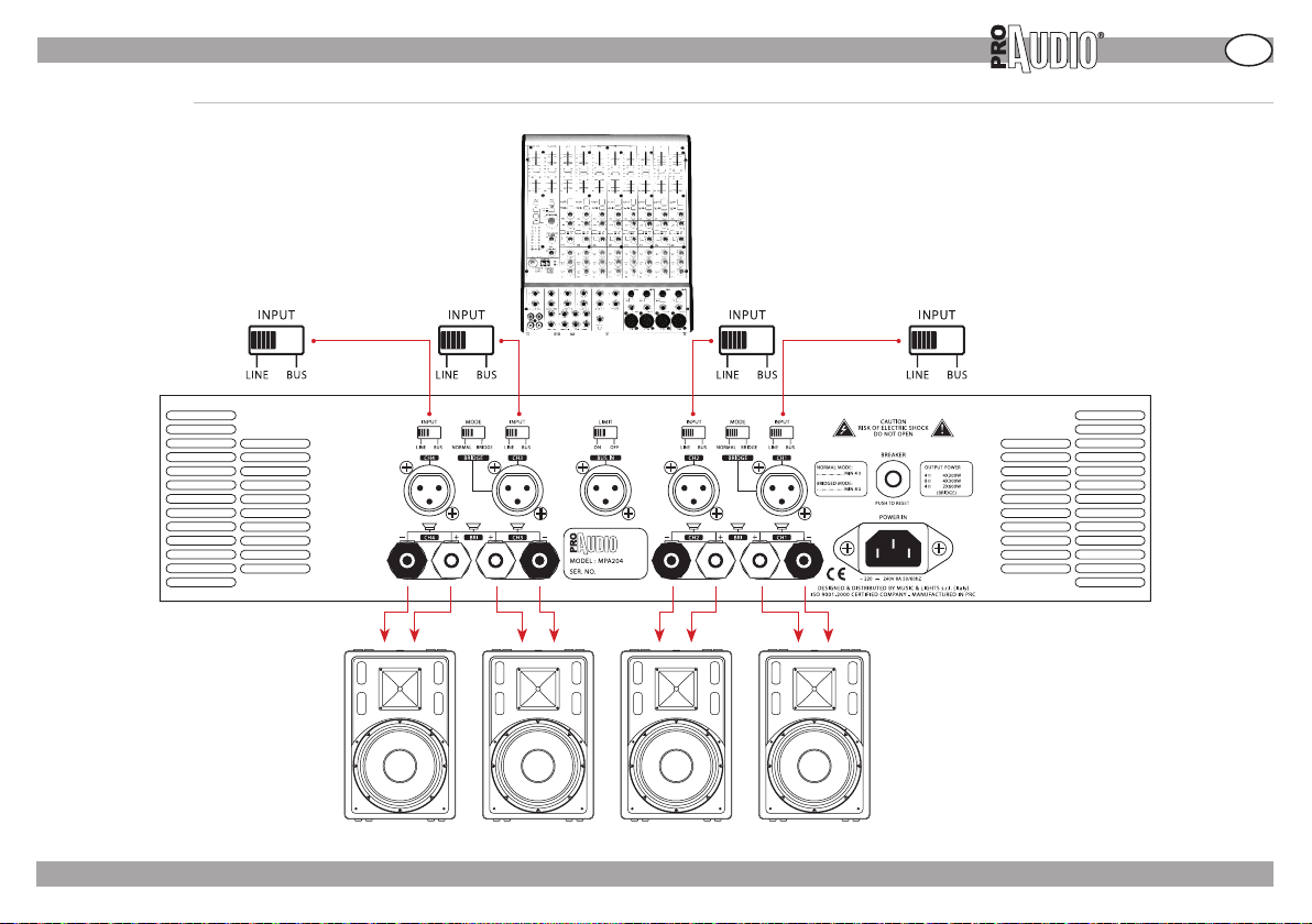
» CONNECTIONS
4 CHANNELS MODE
MIXER
MPA204
GB
LOUDSPEAKERS
FP- 05 /12/07 - Rev01 - ©2007 Music & Lights s.r.l. - Italy - www.musiclightsitaly.com
7
Page 22
GB
MPA204
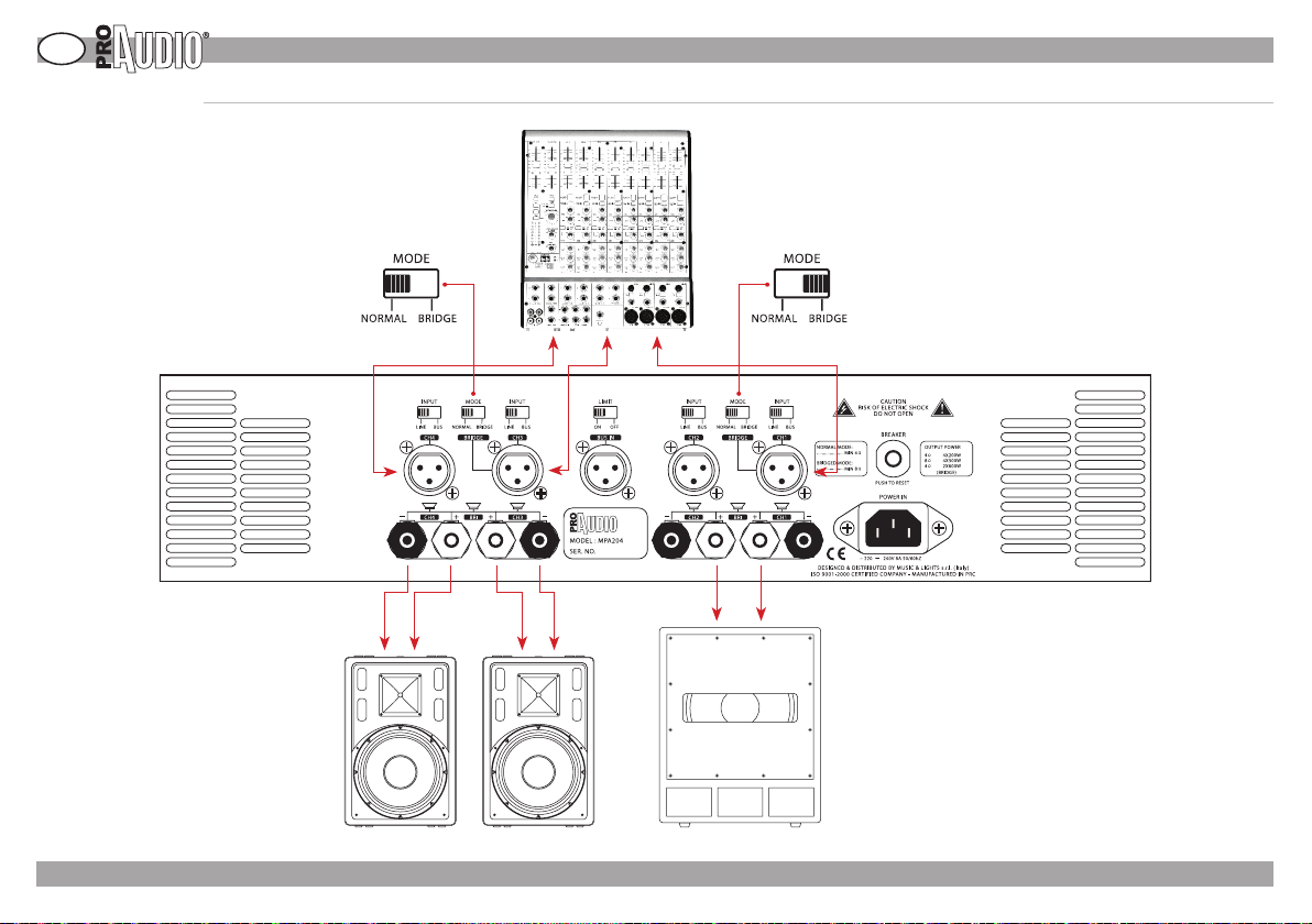
» CONNECTIONS
STEREO + SUB MODE
MIXER
LOUDSPEAKERS (FULL RANGE)
©2007 Music & Lights s.r.l. - Italy - www.musiclightsitaly.com - FP- 05 /12/07 - Rev01
SUBWOOFER
8
Page 23
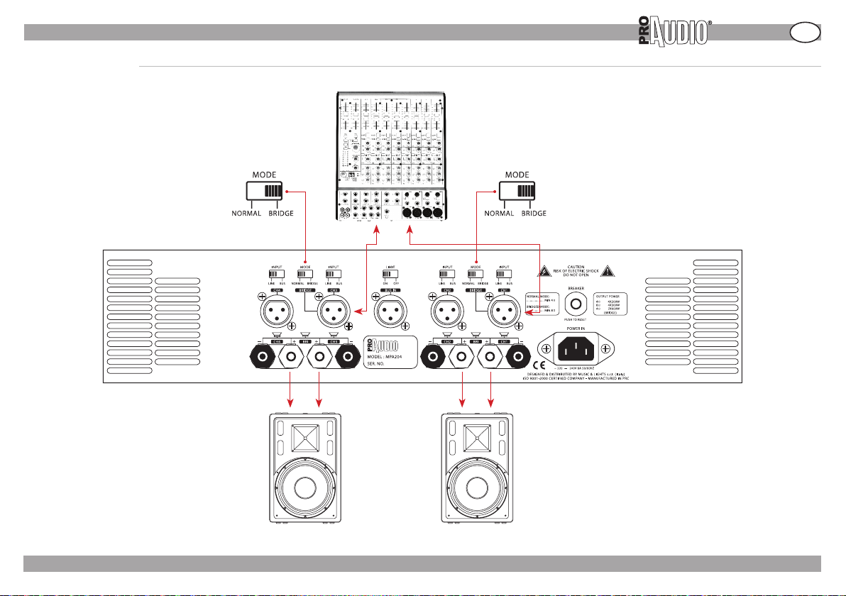
» CONNECTIONS
BRIDGE STEREO MODE
MIXER
MPA204
GB
LOUDSPEAKERS (FULL RANGE)
FP- 05 /12/07 - Rev01 - ©2007 Music & Lights s.r.l. - Italy - www.musiclightsitaly.com
9
Page 24
GB
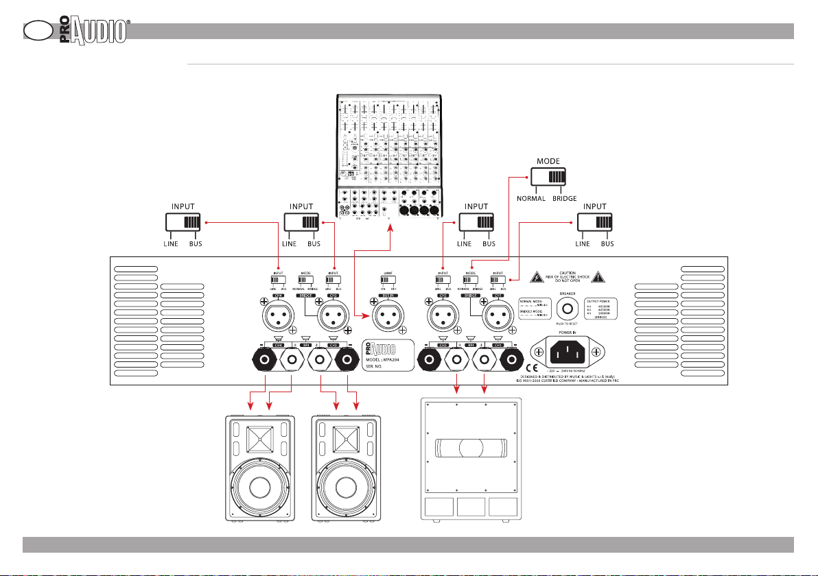
Channel Mode When BUS IN mode
Stereo+sub and Bridge Stereo mode are available when
BUS IN mode. To avoid serious clips when long term
operation at dynamic signal input.
MPA204
» CONNECTIONS
MIXER
©2007 Music & Lights s.r.l. - Italy - www.musiclightsitaly.com - FP- 05 /12/07 - Rev01
SUBWOOFERLOUDSPEAKERS
10
Page 25

» BRIEF NOTES ON ACOUSTIC
Brief notes on acoustic.
Diusing sound into an environment means to distribute sound signals to a given audience
and the results are dependent on several ambient factors (room shape, volume, etc...), the
number of the people present and their precise location, the type of sound source (live or
recorded music or speech), and the level of the background ambient noise.
EFFICIENCY
Sound pressure (SPL) of a speaker depends on three factors:
efficiency, dimensions and use in combination with other speakers.
Efficiency, the quantity of energy generated by the amplifier trasformed into sound,
determines the volume that can be obtained by an amplifier of a given power rating. A 50W
amplifier combined with highly efficient speakers may be able to produce a higher volume
than a 100W amplifier combined with less efficient speakers.
IMPEDANCE
One of the electrical features of a speaker is its impedance (resistance to the passage of
alternate current). Both resistance and impedance
varies at dierent frequencies so dierent frequencies can be delivered with dierent soiund
pressure levels. In some cases, confusion may arise when combining impedence values of
power amplifiers with those of loudspeakers.
Adapting the output impedance of the amplifier to the loudspeaker’s input impedance means
that all the energy from the amplifier will be transferred to the speakers with no signal losses,
so that the system works in optimum conditions (and the risk of damage is minimised).
A louspeaker having an higher impedance than power amplifier’s may be used, although
this will result in a power reduction; loudspeakers with an impedance lower than amplifier’s
minimum load, must not be connected.
If more complex systems (e.g. several speakers connected to the sameamplifier) are adopted,
you must be sure that the overall speaker impedance value corresponds to the amplifier
output impedance.
There are two possible connection systems: series or parallel mode.
Connecting two speakers in series means to connect the positive pole of the first speaker to
the negative pole of the second one and
then to connect the two free poles to the amplifier.
In this case the impedance values are summed up: e.g. Two 8 Ohm speakers connected in
parallel give a 16 Ohm load.
To connect two speakers in parallel mode, simply interconnect the two speakers terminals of
the same sign. To obtain the total value, in this case a calculation is required. Indicating R1 and
R2 as the two loudspeaker values, the following formula has to be used: (R1 x R2) / (R1 + R2).
E.g.: with two 8 Ohm speakers, we have that:
(8x8)/(8+8) = 64/16 = 4 Ohm, that is to say that when identical speakers are connected in
parallel, the impedance value is halved.
CHOOSING THE RIGHT AMPLIFIER
According to the AES standard, tests run on the components require a two-hour stressing oF
FP- 05 /12/07 - Rev01 - ©2007 Music & Lights s.r.l. - Italy - www.musiclightsitaly.com
MPA204
a filtered pink noise signal with a pass band of a decade and with a crest factor (average
value and peak value ratio) of 6 dB. For common applications which require both a
high power and a high reliability level, it is advisable to use power amplifiers with an
output rating equivalent to the AES power rating of the enclosures. This ensures that the
enclosures will operate within their thermal limit specification. For applications where
the user desires to take advantage of the full applicable power of the enclosures, it is
possible to use amplification with output power ratings equal to the program output
rating of the enclosures. In this configuration, the full capacity of the system to handle
transient power is utilised, however it will be necessary to constantly monitor and
regulate the system very carefully in order to avoid overloading the speakers.
It is also necessary to avoid that loudspeakers are subject to signals which could cause
them to exceed their mechanical limits or their applicable frequency limits. In practice, it
is possible to damage a loudspeaker with a power well below its AES applicable power
rating if it is required to reproduce a distorted signal at a low frequency that causes a
cone excursion beyond the physically consented limit.
GLOSSARY
SPL: Sound pressure level is a logarithmic measure of the rms sound pressure of a
sound relative to a reference value. It is measured in decibels (dBSPL).
AES: Established in 1948, the Audio Engineering Society (AES) draws its membership
from amongst engineers, scientists, manufacturers and other organizations and
individuals with an interest or involvement in the professional audio industry. They are
mainly engineers developing devices or products for audio, and also people working
in audio content production.The Audio Engineering Society is the only professional
society devoted exclusively to audio technology. Its membership of leading engineers,
scientists and other authorities has increased dramatically throughout the world,
greatly boosting the society’s stature and that of its members in a truly symbiotic
relationship. The organisation develops, reviews and publishes engineering standards
for the audio and related media industries, and produces the AES Conventions, which
are held twice a year alternating between Europe and the USA. The AES and individual
national “Sections” also hold AES Conferences on dierent topics during the year.The
AES publishes a peer-reviewed journal, the Journal of the Audio Engineering Society
(JAES).
RMS: Root-mean-square (rms) refers to the most common mathematical method of
dening the eective voltage or current of an AC wave. The name comes from the fact
that it is the square root of the mean of the squares of the values.
PARALLEL: Either when a signal is split and routed down two separate paths before
being re-combined, or when speakers are connected + to + and - to -. Opposite of
series.
GB
11
Page 26

Notes/comments:
Page 27

Page 28

Music & Lights S.r.l.
Via Appia Km. 136,200
04020 ITRI (LT) Italy
P.IVA/V.A.T. IT 02057590594
www.musiclights.it
[email protected]
Ucio Italia
tel. +39 0771 72190
fax +39 0771 721955
Foreign Oce
tel. +39 0771 721966
fax +39 0771 721977
www.musiclights.it
 Loading...