

Page 1
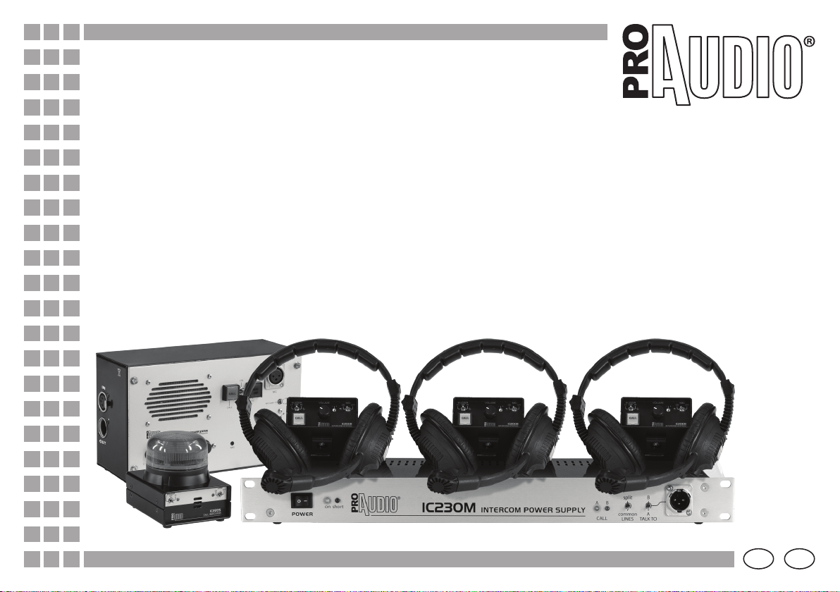
INTERCOM 200 series
Manuale
User Manual
©2009 Music & Lights s.r.l. - Italy - www.proaudioline.it
I GB
Page 2

Page 3

Introduzione
Vi siamo grati per aver scelto un prodotto ProAudio.
La serie Intercom 200 di sistemi di comunicazione “made in
Italy” offre elevata intelligibilità nella trasmissione di voce e
audio, senza limitazioni in fatto di distanza, trovando ampia
possibilità di applicazione in occasioni quali spettacoli, concerti,
rappresentazioni teatrali ed eventi sportivi, nonché produzioni
televisive, sfilate di moda, luoghi di culto, ambienti industriali e
strutture sanitarie. I singoli componenti della serie sono realizzati
in modo da rivelarsi maneggevoli e al tempo stesso robusti,
per non temere l’uso nelle situazioni live più critiche. Anche in
ambienti particolarmente rumorosi, avvisatori acustici e luminosi
opportunamente attivabili segnalano le chiamate attive. Il sistema
di attenuazione dei rumori minimizza disturbi e feedback per avere
una trasmissione audio efficace.
L’uso della connessione XLR rende i componenti della serie
Intercom 200 compatibili con sistemi di terze parti.
INTERCOM 200 SERIES
Indice
Sicurezza
Panoramica degli accessori
Struttura e collegamenti
Alimentazione
Stazioni
Specifiche tecniche e compatibilità
I
4
5
6
7
8/9
10
Le informazioni riportate in questo manuale sono state attentamente controllate.
Music & Lights non si assume, tuttavia, responsabilità derivanti da eventuali inesattezze.
Tutte le specifiche possono variare senza alcuna notifica.
FP- 10 /05/09 - Rev001 - 05/09 ©2009 Music & Lights s.r.l. - Italy - www.proaudioline.it
Page 4
I
PRECAUZIONI
• Leggere attentamente tutta la documentazione prima di installare il sistema e conservarla in un luogo sicuro per un riferimento futuro.
• Non installare il sistema vicino all’acqua o comunque in zone umide.
• Pulire esclusivamente tramite l’uso di un panno asciutto.
• Non ostruire in alcun modo le eventuali griglie di areazione.
• Controllare che il voltaggio della rete sia identico a quello stampato sul retro dell’unità di alimentazione.
Danni causati da connessione a voltaggi impropri, non sono coperti da alcuna garanzia.
• Qualora la spina del cavo in dotazione non corrispondesse con la presa a muro da utilizzare per l’alimentazione, consultare un tecnico qualicato per risolvere il
problema. In particolare controllare che l’impianto elettrico sia dotato di una efficiente messa a terra e controllare che la presa a muro e la spina del cavo di
alimentazione siano perfettamente compatibili.
• Proteggere il cavo di alimentazione e le sue spine di connessione, da qualsiasi contatto involontario: calpestamenti, urti, abrasioni ecc..
• Scollegare l’unità di alimentazione durante temporali e se non utilizzata per lungo tempo.
• Rivolgersi a personale qualicato per qualsiasi tipo di riparazione e/o controllo come ad esempio: cavo di alimentazione danneggiato, liquido penetrato nelle unità,
oggetti penetrati nelle unità, le unità sono state esposte a pioggia o eccessiva umidità, le unità non operano normalmente o hanno subito traumi di qualsiasi genere.
• Questi dispositivi sono conformi a tutte le direttive dell’UE e pertanto riportano la sigla .
• Se si desidera eliminare i dispositivi denitivamente, consegnarli
per lo smaltimento ad un’istituzione locale per il riciclaggio.
INTERCOM 200 SERIES
ATTENZIONE! Prima di eettuare qualsiasi operazione, leggere con attenzione questo manuale:
contiene informazioni importanti riguardo l’installazione e l’uso del sistema.
PER RIDURRE IL RISCHIO DI SHOCK ELETTRICO NON RIMUOVERE CHASSIS O PANNELLI PROTETTIVI
RIVOLGERSI A PERSONALE QUALIFICATO - EVITARE DI ESPORRE IL SISTEMA ALLA PIOGGIA O A LIQUIDI
» SICUREZZA
Per qualsiasi necessità si prega di contattare il nostro ucio tecnico:
tel. +39 0771 72190 fax +39 0771 721955 - [email protected]
FP- 10 /05/09 - Rev001 - 05/09 ©2009 Music & Lights s.r.l. - Italy - www.proaudioline.it
4
Page 5
» PANORAMICA ACCESSORI
PANORAMICA DEGLI ACCESSORI PER SISTEMI INTERCOM 200
INTERCOM 200 SERIES
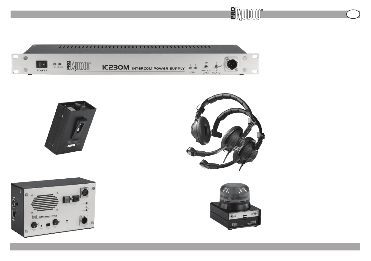
IC230M
Unità di alimentazione.
• Supporta il collegamento di un massimo
di 30 stazioni portatili IC200B e 10 stazioni
portatili IC210A.
• Misure (LxAxP): 483x44x190 mm.
• Peso: 2.8 Kg.
I
IC200B
Stazione portatile (beltpack).
• Gancio per cintura rimovibile.
• Misure (LxAxP): 90x42x126 mm.
• Peso: 340 g.
IC210A
Stazione altoparlante - cuffia, ideale per
applicazioni fisse o mobili.
• Ingresso per microfono con guadagno
regolabile ed alimentazione phantom.
• Diverse possibilità di ssaggio: a pare-
te, ad incasso, su piano.
• Misure (LxAxP): 220x130x80mm.
• Peso: 700 g.
FP- 10 /05/09 - Rev001 - 05/09 ©2009 Music & Lights s.r.l. - Italy - www.proaudioline.it
ICH02 ICH01
Cua bi-aurale (ICH02) e mono-aurale
(ICH01) professionale con microfono
dinamico integrato.
• Connessione XLR 4-poli, compatibile
con sistemi di terze parti.
• Peso: 250 g. (ICH02) e 210 g. (ICH01).
IC220S
Indicatore remoto di chiamata
per applicazioni fisse o mobili.
• Ideale in ambienti molto rumorosi o nel
caso l’indicatore di chiamata della staz one beltpack non sia ben visibile.
• Dimensioni (LxAxP): 90x105x108mm.
• Peso: 500g.
5
Page 6
I
INTERCOM 200 SERIES
» STRUTTURA DEL SISTEMA E COLLEGAMENTI
STRUTTURA DEL SISTEMA E COLLEGAMENTI
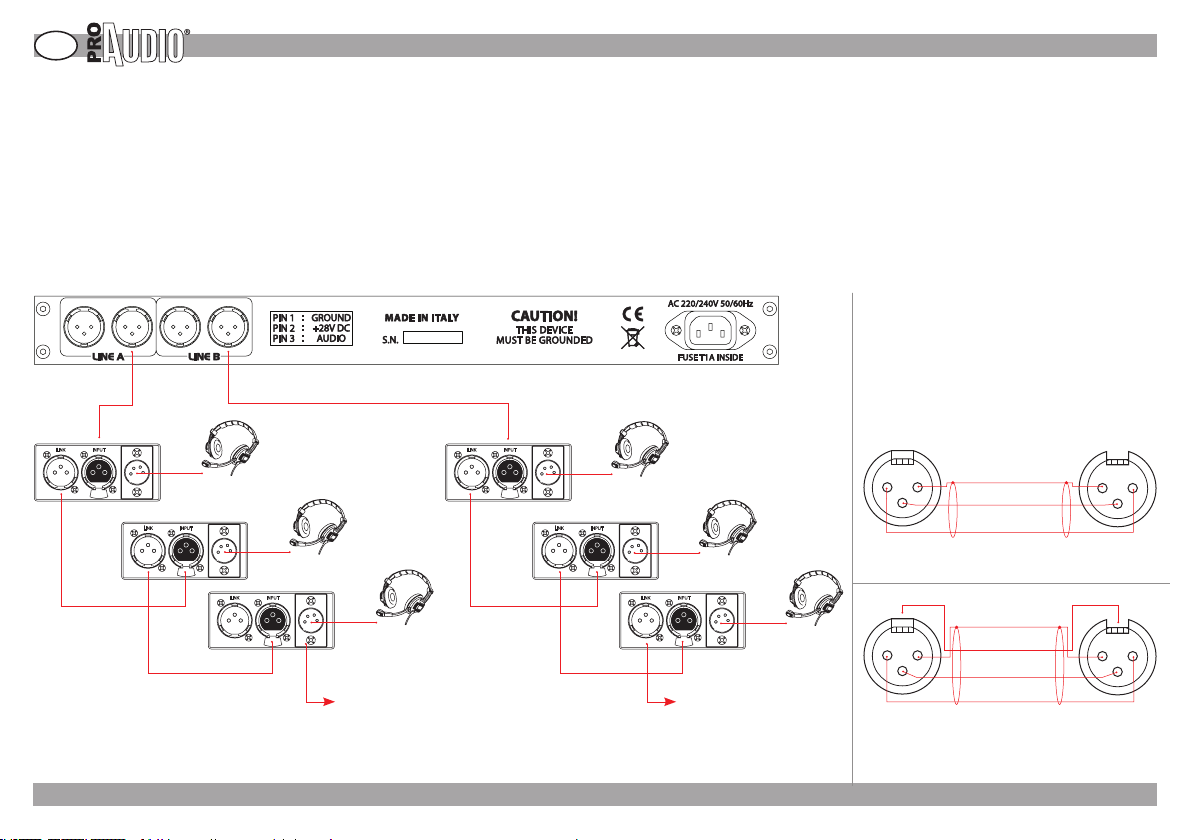
I sistemi intercom su filo permettono alle stazioni collegate di comunicare tra loro in modo bidirezionale.
Tutte le stazioni sono in collegamento “FULL DUPLEX” e non occorre premere nessun pulsante per parlare.
Per formare un sistema intercom sono necessari un alimentatore (IC230M) e almeno due stazioni (portatili IC200B oppure IC210A).
Al connettore (XLR3 maschio) dell’alimentatore va collegato il connettore INPUT (XLR3 femmina) della stazione (portatili IC200B oppure IC210A).
Le stazioni successive vanno collegate ai connettori LINK (XLR3 maschio) delle stazioni precedenti. Questo tipo di collegamento e` detto anche “PARTY LINE”. [Fig.01]
La caratteristica fondamentale e` il collegamento, basato su cavi standard microfonici XLR 3 poli (2 conduttori + schermo). Un conduttore (pin 3) porta il segnale audio, il
secondo conduttore (pin 2) porta l’alimentazione (24 ÷ 30 V c.c.) alle stazioni sulla linea, la schermo (pin 1) porta la massa comune. [Fig.02]
E` possibile utilizzare cavo schermato microfoni-
co standard a 2 conduttori + schermo
[Fig.02].
Per collegamenti molto lunghi si consiglia l’uso di
cavi a 3 conduttori + schermo, di sezione almeno
0.18 mmq , collegando anche il telaio (carcassa )
dei connettori XLR (13).
IC230M (Unità di Alimentazione)
La lunghezza massima del collegamento può superare i 500 m, avendo cura di usare cavi di sezio-
ne elevata e con schermatura efficiente.
[Fig.03]
LINK INPUT
FIG. 01
LINK INPUT
headset
ICH01 o ICH02
LINK INPUT
LINK INPUT
XLR 3P M XLR 3P F
2 1
3
LINK INPUT
FIG. 02
LINK INPUT
XLR 3P M XLR 3P F
241
3
FIG. 03
FP- 10 /05/09 - Rev001 - 05/09 ©2009 Music & Lights s.r.l. - Italy - www.proaudioline.it
(1) MASSA (schermo)
(3) AUDIO
(2) ALIMENTAZIONE
Cablaggio con cavo 2 conduttori + schermo.
( Standard microfonico ).
(1) MASSA (schermo)
(4) TELAIO
(3) AUDIO
(2) ALIMENTAZIONE
Cablaggio con cavo 3 conduttori + schermo.
( Consigliato per collegamenti molto lunghi ).
1 2
142
3
3
6
Page 7
» UNITA’ DI ALIMENTAZIONE
UNITA’ DI ALIMENTAZIONE
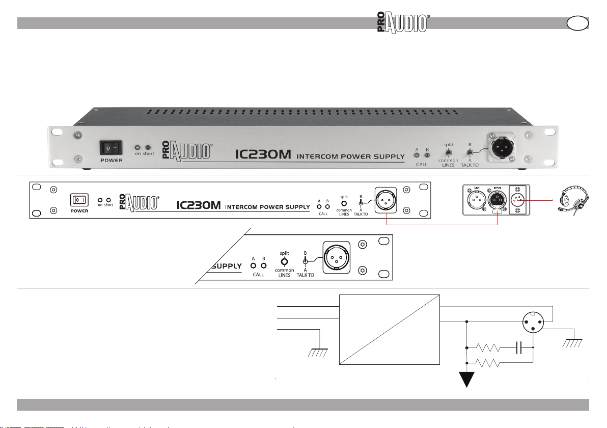
L’unità d’alimentazione IC230M permette di avere due linee A e B indipendenti (SPLIT) (non comunicano tra di loro) , che possono essere messe in comune (COMMON)
mediante un selettore frontale (quando il selettore è su “common” le linee A e B comunicano tra di loro). [Fig.04]
E` presente un ulteriore connettore frontale a cui collegare una stazione portatile che può fungere da “MASTER” e può essere messa in comunicazione con le linee A o B
mediante il selettore frontale TALK TO [Fig.04]. Se le linee sono in comune (common), questa stazione sarà sempre collegata ad entrambe le linee, indipendentemente dalla
posizione del selettore frontale TALK TO [Fig.04].
FIG. 04
INTERCOM 200 SERIES
LINK INPUT
I
L’unità d’alimentazione IC230M fornisce la tensione di alimentazione alle
stazioni e la corretta terminazione alla linea audio (4700Ω in c.c., 220Ω in
gamma audio). Le stazioni sono collegate in parallelo alla linea e grazie alla
loro alta impedenza di ingresso presentano un carico trascurabile sulla linea
stessa, per cui il numero massimo di stazioni collegabili e' limitato solo dalla
massima corrente erogabile dall'alimentatore (L’IC230M supporta no a 30
unità IC200B) e no a 10 unità ’IC210A.
L’unità d’alimentazione IC230M è dotata di protezione elettronica contro
sovraccarichi e/o errati collegamenti.
FP- 10 /05/09 - Rev001 - 05/09 ©2009 Music & Lights s.r.l. - Italy - www.proaudioline.it
L
N
E
RETE
FIG. 05
~
+28 V cc
MASSA 1 2
3
AUDIO
=
TERMINAZIONE LINEA
7
Page 8
I
STAZIONI
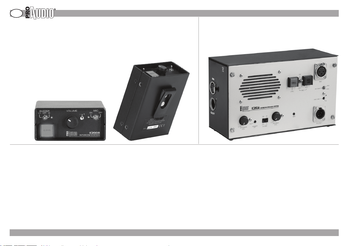
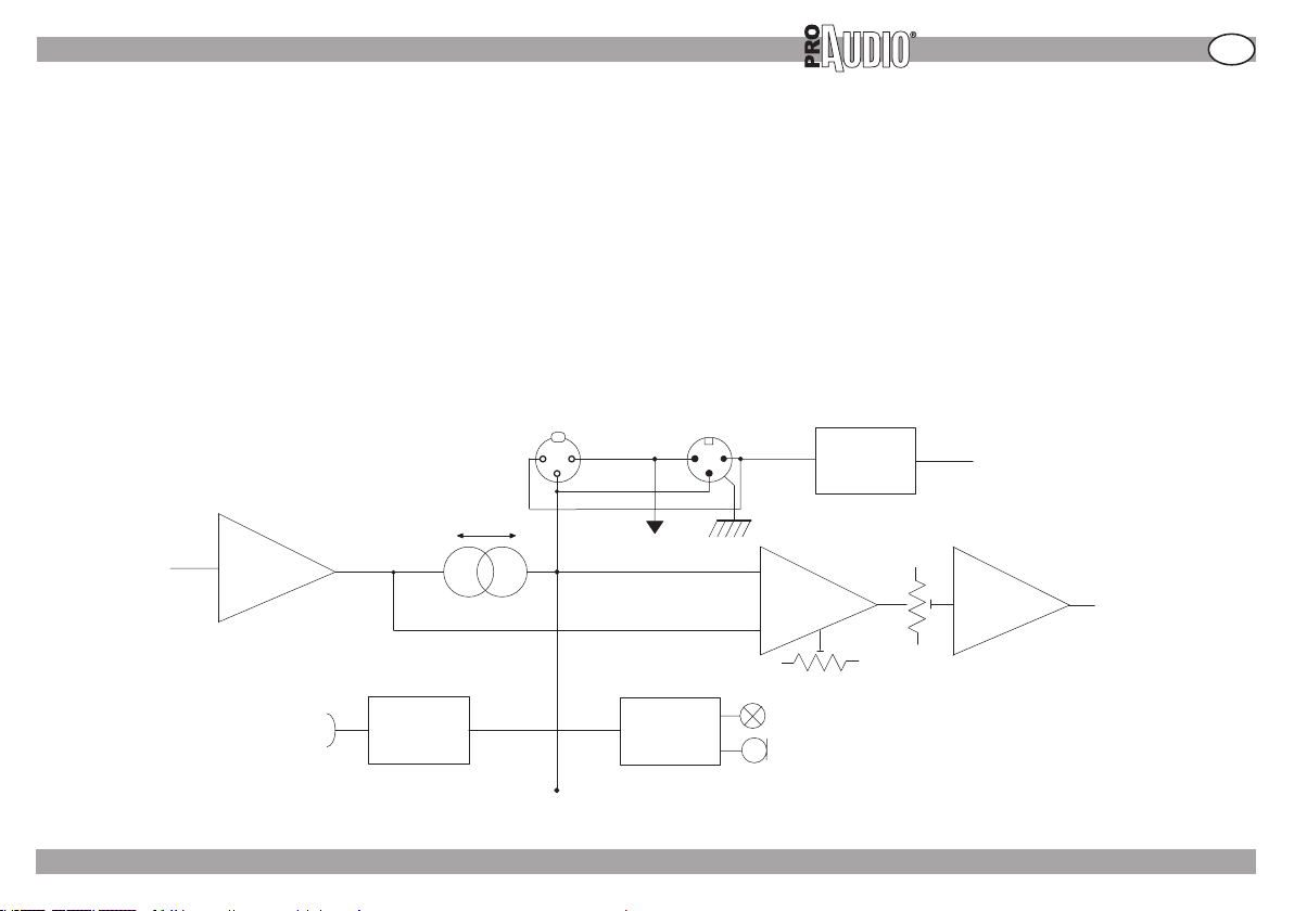
Ogni stazione e` formata da 5 blocchi [Fig.08]
• Preamplicatore microfonico.
• Circuito di “SIDE TONE”.
• Amplicatore cua.
• Circuito di chiamata.
• Circuito di alimentazione.
FIG. 06 FIG. 07
Preamplicatore microfonico
Le stazioni sono previste per l’uso di microfoni dinamici a bassa impedenza (600 Ω nominali), sbilanciati.
Il segnale del microfono viene preamplificato, equalizzato per una migliore comprensibilità e iniettato sulla linea audio comune.
Il preamplicatore è disinseribile mediante l’interruttore MIC ON/OFF. Se il microfono non e` collegato, il preamplicatore è automaticamente escluso, e non introduce
quindi rumore sulla linea.
Circuito di SIDE TONE
Sulla linea audio è presente il segnale proveniente dai microfoni di tutte le stazioni collegate. Se questo segnale venisse inviato direttamente alla cua, l’utente riceverebbe anche la propria voce, e sarebbe presente il rischio di inneschi e ritorni acustici tra la cua e il microfono, soprattutto quando la cua non e` indossata.
Il segnale presente sulla linea audio viene quindi inviato all’amplificatore della cuffia attraverso un circuito che sottrae il segnale del microfono della stazione.
Questo circuito e` regolabile mediante un trimmer (SIDE TONE) che permette di annullare (posizione centrale) il segnale del microfono o di lasciarlo arrivare in cua con
livello e fase regolabile (ruotando in senso orario o antiorario).
Alcuni operatori preferiscono avere in cuffia un ritorno del proprio microfono, per essere sicuri che il microfono stesso sia funzionante.
Questo comando non inuenza il segnale inviato alle altre stazioni.
INTERCOM 200 SERIES
» STAZIONI
FP- 10 /05/09 - Rev001 - 05/09 ©2009 Music & Lights s.r.l. - Italy - www.proaudioline.it
8
Page 9
» STAZIONI
INTERCOM 200 SERIES
Amplicatore della cua
E` previsto l’uso di cue ad alta impedenza (100 ÷ 1000 Ω)
Il segnale di uscita dal circuito del SIDE TONE viene inviato all’amplicatore della cua attraverso un controllo di volume.
Il circuito e` protetto contro corto circuiti e sovraccarichi.
La stazione modello IC210A [Fig.07] dispone anche di un altoparlante interno, con amplicatore e controllo di volume indipendenti.
Circuito di chiamata
Un sistema di chiamata luminosa e acustica e` attivato premendo il tasto CALL sulle stazioni. Viene iniettata una tensione continua sulla linea audio, che causa
l’accensione delle spie luminose CALL e l’azionamento degli avvisatori acustici (BUZZER).
Circuito di alimentazione
La tensione di alimentazione (pin 2 del connettore XLR) viene applicata al circuito delle stazioni attraverso un circuito di protezione contro le inversioni di polarità e un
filtro antidisturbo.
1
INPUT
2
3
GND
AUDIO
1
2
+28 V
LINK
3
SUPPLY
PROTECTION
+V
I
MIC
IN
FIG. 08
MIC
PRE-AMP
CALL
+
SIDE
TONE
PHONES
AMP
-
SIDE TONE
CALL
SEND
CALL
RECEIVE
CALL LAMP
BUZZER
FP- 10 /05/09 - Rev001 - 05/09 ©2009 Music & Lights s.r.l. - Italy - www.proaudioline.it
VOLUME
PHONES
OUT
9
Page 10
I
INTERCOM 200 SERIES
SPECIFICHE TECNICHE E COMPATIBILITA’
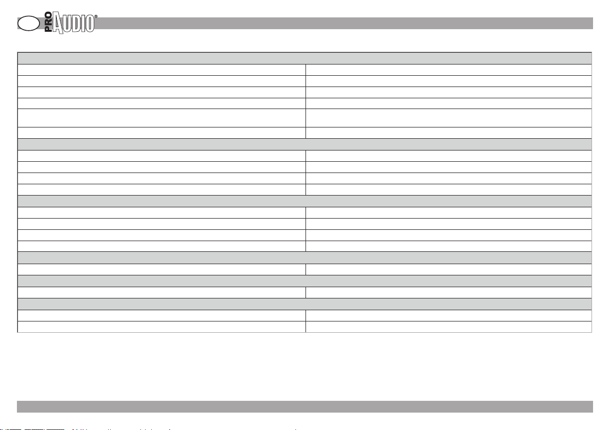
Impedenza carico di linea 4700 Ω in c.c. 220 Ω in gamma audio –
Livello nominale -17 dBm
Livello massimo +4 dBm
Tensione di alimentazione 15÷30 V cc, 28 V nominali, 36 V massimi
Assorbimento (a 28 V nominali) 15 mA a riposo, 50 mA max in chiamata (IC200B)
Impedenza di ingresso stazione 18 KΩ (equivalenti, in parallelo alla linea)
Risposta in frequenza 150 Hz ÷ 13 KHz (equalizzato per una migliore intelligibilita`)
Impedenza di ingresso 1 KΩ (per microfoni dinamici da 200 Ω a 1 KΩ)
Massimo livello in ingresso -30dBm
Risposta in frequenza 150 Hz ÷ 18 KHz (± 2 dB)
Massimo livello di uscita +20 dBm (su 1 KΩ)
Impedenza di carico cuffie da 200 a 1000 Ω, 32 Ω minimo
Potenza di uscita 3 W max, 10% THD
Regolazione del SIDE TONE ± 30 dB, - 60 dB minimo a centro corsa
Tensione nominale + 12 V cc sulla linea audio
» SPECIFICHE TECNICHE E COMPATIBILITA’
Dati tecnici generali
60 mA a riposo, 200 mA max (IC210A)
Preamplicatore microfonico
Guadagno 29 dB
Amplicatore cua
Guadagno +40 dB
Amplicatore altoparlante IC210A (stazione altoparlante)
Side tone
Circuito di chiamata
Sensibilità + 2 V cc
Compatibilita`
L’unità è compatibile con sistemi di altri costruttori. Per maggiori informazioni richiedere la scheda di compatibilità.
FP- 10 /05/09 - Rev001 - 05/09 ©2009 Music & Lights s.r.l. - Italy - www.proaudioline.it
10
Page 11
Altre note e/o commenti:
Page 12

Page 13

Introduzione
Thanks for choosing a ProAudio product.
Made-in-Italy Intercom 200 Series provides a highly intelligible
voice and music transmission even at long cable runs. Intercom
200 systems are widely used in live performance theaters, concert
halls and sport stadiums. They are also found in small to midsized TV/broadcast studios, smaller broadcast production trucks,
industrial settings, houses of worship and in hospitals. The system
provides easy setup and operation. In addition to a ashing light
alert, a switchable buzzer makes the user aware of calls, even in
noisy environments. All components are constructed and proven
to withstand rugged usage in fast-paced, demanding and high
intensity applications. Even under the most challenging conditions,
the noise attenuating headsets and noise-cancelling microphones,
combined with sidetone nulling circuitry, minimize acoustic
noise and feedback to provide superior audio quality. Use of XLR
connection makes Intercom 200 components highly compatible
with third-party sets.
INTERCOM 200 SERIES
Index
Safety
Accessories overview
System structure and connection
Power supply
Stations
Technical specifications/compatibility
GB
14
15
16
17
18/19
20
Design and specifications
are subject to change without notice.
FP- 10 /05/09 - Rev001 - 05/09 ©2009 Music & Lights s.r.l. - Italy - www.proaudioline.it
Page 14
GB
WARNING! Please read the instruction carefully which includes important information about the installation, usage and maintenance.
TO PREVENT ELECTRIC SHOCK DO NOT REMOVE TOP OR BOTTOM COVERS. DO NOT EXPOSE THIS EQUIPMENT TO RAIN OR MOISTURE
PRECAUTIONS
• Read all documentation before using your equipment. Retain all documentation for further reference.
• Do not use this apparatus near water.
• Clean only with a dry cloth.
• Do not block any ventilation openings.
• Do not install near any heat sources such as radiators, heat exchangers, stoves, or other apparatus that produce heat.
• Mains voltage must be correct and the same as that printed on the rear of the unit.
• Always operate the unit with the AC ground wire connected to the electrical system ground.
• Protect the power cord from being walked on or pinched, particularly at plugs, convenience receptacles, and the point where they exit from the apparatus.
• Unplug this apparatus during lightning storms or when unused for long periods of time.
• Refer all servicing to qualied service personnel. Servicing is required when the apparatus has been damaged in any way, such when the mains cord or plug are da-
aged., liquid has been spilled or objects have fallen into the apparatus, the apparatus has been exposed to rain or moisture, does not operate normally, or has been
dropped.
• The unit corresponds to all required directives of the EU and is therefore marked with .
• If the unit is to be put out of operation denitively, take it to a local
recycling plant for a disposal which is not harmful to the environment.
INTERCOM 200 SERIES
NO USER SERVICEABLE PARTS INSIDE - REFER SERVICING TO QUALIFIED SERVICE PERSONNEL.
» SAFETY
For further information please contact our Service Center:
tel. +39 0771 72190 fax +39 0771 721955 [email protected]
FP- 10 /05/09 - Rev001 - 05/09 ©2009 Music & Lights s.r.l. - Italy - www.proaudioline.it
14
Page 15
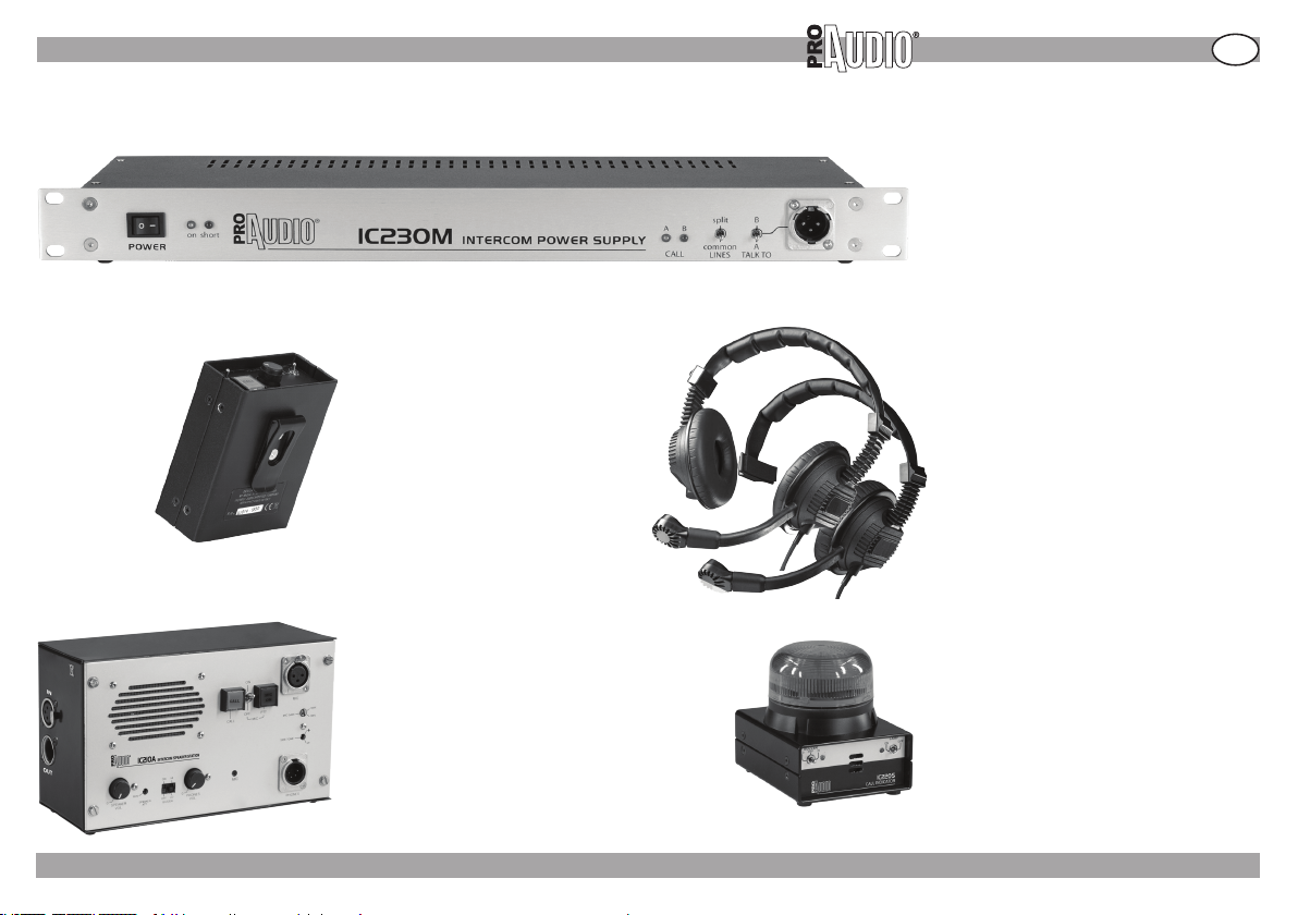
» ACCESSORIES OVERVIEW
INTERCOM 200 series accessories overview
INTERCOM 200 SERIES
IC230M
Power supply unit.
• Supporting up to 30 IC200B beltpack
units and 10 IC210A speaker stations.
• Dimensions (WxHxD): 483x44x190 mm.
• Weight: 2,8 kg.
GB
IC200B
Portable belt-pack unit.
• Removable belt clip.
• Dimensions (WxHxD): 90x42x126 mm.
• Weight: 340 g.
IC210A
Speaker / headset station, suitable for fixed
or mobile installations.
• Microphone input with adjustable gain and
phantom power.
• Dierent xing possibilities (wall, ush,
tabletop)
• Dimensions (WxHxD): 220x130x80mm.
• Weight: 700 g.
FP- 10 /05/09 - Rev001 - 05/09 ©2009 Music & Lights s.r.l. - Italy - www.proaudioline.it
ICH02 ICH01
Professional double-ear (ICH02) and
single-ear (ICH01) headsets with built-in
dynamic microphone.
• 4-pin XLR connection, compatible with
third-party systems.
• Weight: 250 g. (ICH02) and 210 g.
(ICH01).
IC220S
Remote call indicator suitable for fixed or
mobile installations.
• Ideal in very noisy surroundings or in case
the call indicator light is not well visible.
• Dimensions (WxHxD): 90x105x108mm.
• Weight: 500g.
15
Page 16
GB
INTERCOM 200 SERIES
» SYSTEM STRUCTURE AND CONNECTION
SYSTEM STRUCTURE AND CONNECTION
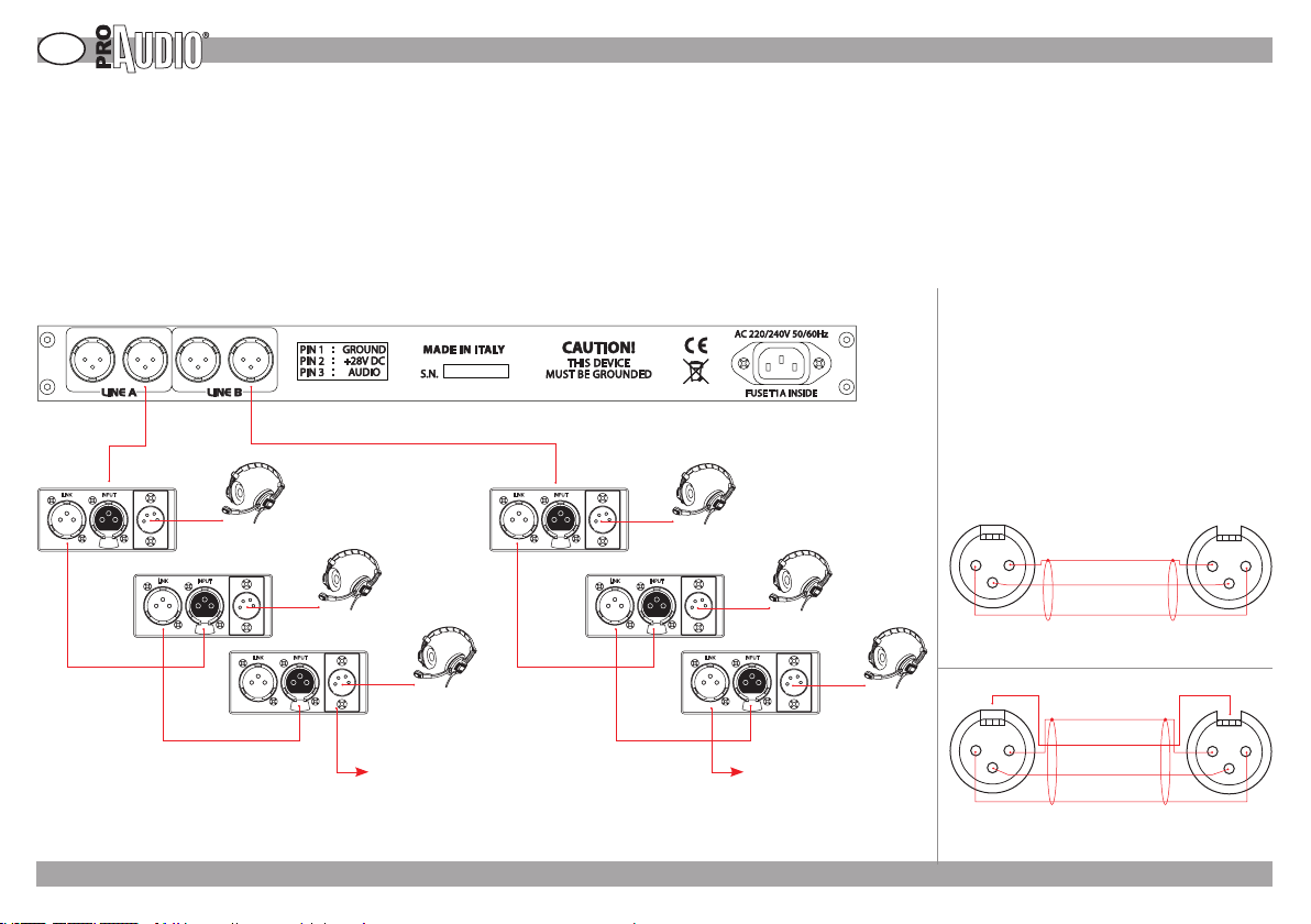
Wired intercom systems allow the connected station to communicate in a bi-directional mode.
The connection is “FULL DUPLEX”, and no talk button or switch is needed. All users can communicate “hands free”.
A basic intercom system is made up with a power supply (model IC230M) and at least two beltpack stations (model IC200B) or speaker stations (IC210A).
The power supply OUTPUT connector (male XLR3) is connected to the INPUT connector (female XLR3) of the line’s rst station.
The other stations may be connected to the other output connector of the power supply or to the preceding station’s LINK connector (male XLR3) [PIC.01]
The basic characteristic is that the system interconnection uses standard XLR 3 pin microphone cables (2 conductor + screen) [PIC.02].
One of the conductors (pin 3) carries the audio signal, the other one (pin 2) supplies power (24 ÷ 30 V c.c.) to the remote stations connected to the line, the screen (pin 1)
is the common ground. [PIC.02]
For connection to the remote stations, it is pos-
sible to use standard microphone cable ( 2 conductors + screen)
[PIC.02], but, in case of very
long connections we strongly suggest to use
a 3 conductors + screen cable, having at least
IC230M (Power supply)
0.18 mm2 conductors, using the third conduc-
tor to connect the XLR connector’s body (frame) (13). Maximum cable length may be more
than 500 m, if cables with large conductors and
LINK INPUT
LINK INPUT
headset
ICH01 or ICH02
LINK INPUT
LINK INPUT
LINK INPUT
LINK INPUT
PIC. 02
PIC. 01 PIC. 03
FP- 10 /05/09 - Rev001 - 05/09 ©2009 Music & Lights s.r.l. - Italy - www.proaudioline.it
good screening are used.
XLR 3P M XLR 3P F
2 1
(1) GROUND (screen)
3
2 conductors + screen wired cable.
( Microphonic standard cable ).
XLR 3P M XLR 3P F
(1) GROUND (screen)
241
3
3 conductors + screen wired cable.
( Suggested for very long connections ).
(3) AUDIO
(2) SUPPLY
(4) FRAME
(3) AUDIO
(2) SUPPLY
[PIC.03]
1 2
3
142
3
16
Page 17
» POWER SUPPLY
POWER SUPPLY
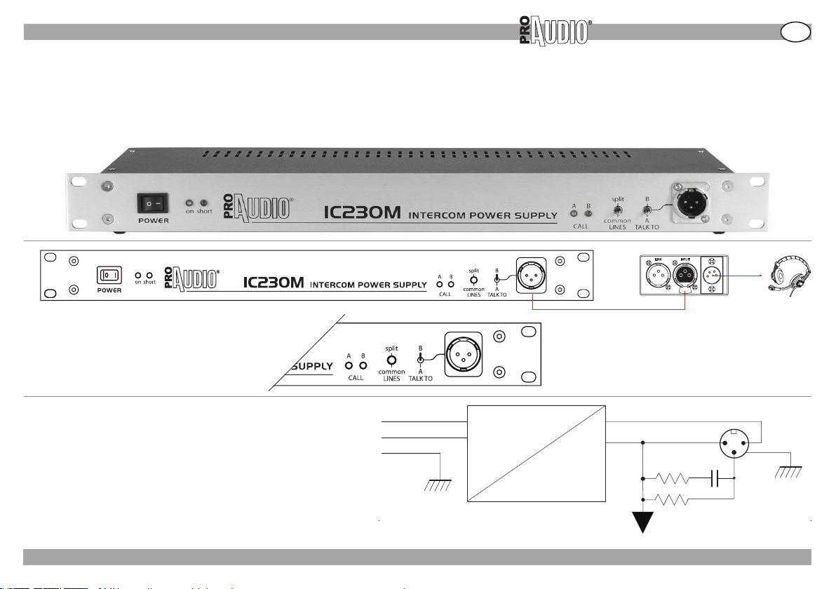
Power supply model IC230M allows for two independent (SPLIT) lines A and B, that may be interconnected (COMMON) by means of a front panel switch (when the switch
selector is on “COMMON” the A and B line are connected).
A front panel XLR3 connector is intended for a master belt-pack station, which may be connected to line A or B by means of the TALK TO switch [Fig.04]; if the A and B line
are in common mode this station will be connected to both lines, indipendently from the “TALK TO” switch selector position. [PIC.04]
PIC. 04
INTERCOM 200 SERIES
LINK INPUT
GB
The IC230M power supply unit supplies dc power to the stations and the
correct load to the audio line (5000 W for dc, 220 W for audio frequencies).
All stations are connected across the line, and due to their high input impedance the loading effect on the line is negligible.
The maximum number of stations that may be connected to a line is thus
limited only by the power supply’s available current. (IC230M support MAX
30 IC200B or 10 IC210A units).
The IC230M power supply is equipped with electronic protection against
electrical and thermal overloads and wiring errors.
FP- 10 /05/09 - Rev001 - 05/09 ©2009 Music & Lights s.r.l. - Italy - www.proaudioline.it
L
N
E
MAINS
PIC. 05
~
+28 V cc
GROUND 1 2
3
AUDIO
=
LINE LOAD
17
Page 18
GB
STATIONS
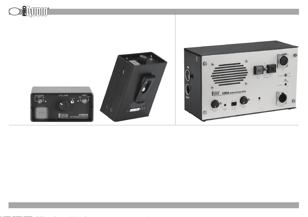
A station includes 5 basic function blocks :
• Microphone preamplier
• SIDE TONE circuit
• Headphones amplier
• Call circuit
• Power supply circuit
PIC. 06 PIC. 07
Microphone preamplier
The stations are designed for use of unbalanced, low impedance dynamic microphones (600 W nominal).
Microphone’s signal is pre-amplied and frequency compensated (equalized) for a better intelligibility, then injected in the common audio line.
The microphone signal may be switched o by the MIC ON/OFF switch. If the microphone is disconnected, the preamplier is automatically defeated, and no noise is
added to the line.
SIDE TONE circuit
The intercom line carries the microphone signals coming from all the connected stations. If these signals were sent directly to the headphones, the user would hear his
own voice, and this could lead to acoustic feedback between headphones and microphone, especially when the headset is not worn. For this reason the signal from the
intercom line is sent to the headphones amplifier by a difference circuit, that subtracts the station’s microphone signal.
This circuit may be adjusted using a trimmer (SIDE TONE) that reduces to a minimum (center position) the station’s microphone signal or allows it to be heard in the headphones with adjustable level and phase (by turning it clockwise or counterclockwise).
Some users prefer to monitor their own microphone’s signal in the headphones, because they want to be reassured that the microphone is properly operating..
This control does not affect the microphone signal received by other stations on the intercom line.
INTERCOM 200 SERIES
» STATIONS
FP- 10 /05/09 - Rev001 - 05/09 ©2009 Music & Lights s.r.l. - Italy - www.proaudioline.it
18
Page 19

» STATIONS
INTERCOM 200 SERIES
GB
Headphones amplier
It is intended for connection to high impedance headphones (100 ÷ 1000Ω).
The SIDE TONE circuit’s output signal is sent to the headphones amplier by a volume control.
The amplifier output is protected against short circuits and overloads.
Models IC210A [PIC.07] speaker station includes both an headphone amplier and an internal loudspeaker, with independent amplier and volume control.
Call circuit
A circuit allowing a visible and acoustic call signaling is activate by pressing the CALL pushbutton. A dc voltage is injected in the audio line, and this results in the CALL
lights ashing. If the buzzer circuit is enabled, an audible signal will be generated, with adjustable volume.
Power supply circuit
Power supply voltage (XLR connector’s pin 2) is applied to the station’s circuitry by means of a protection circuit against polarity reversals, and a noise lter.
1
INPUT
2
3
GND
AUDIO
1
2
+28 V
LINK
3
SUPPLY
PROTECTION
+V
MIC
IN
PIC. 08
MIC
PRE-AMP
CALL
+
SIDE
TONE
PHONES
AMP
-
SIDE TONE
CALL
SEND
CALL
RECEIVE
CALL LAMP
BUZZER
FP- 10 /05/09 - Rev001 - 05/09 ©2009 Music & Lights s.r.l. - Italy - www.proaudioline.it
VOLUME
PHONES
OUT
19
Page 20
GB
INTERCOM 200 SERIES
TECHNICAL SPECIFICATIONS AND COMPATIBILITY
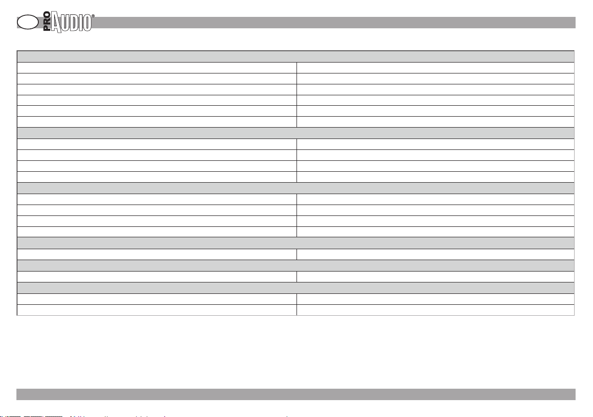
Line impedance 220 Ω (audio) - 4700 Ω (dc)
Nominal line level -17 dBm
Max line level +4 dBm
Supply voltage range 15÷30 V dc, 28 V nominal, 36 V max
Current drain (at 28 V dc) 15mA max when calling (IC200B)
Station input impedance 18 KΩ (equivalent, bridging the intercom line)
Frequency response 150 Hz ÷ 13 KHz (countured for a better intelligibility)
Input impedance 1 KΩ (to be used with 200 Ω ÷ 1 KΩ dynamic microphones)
Gain 29 dB
Max input level -30dBm
Frequency response 150 Hz ÷ 18 KHz (± 2 dB)
Gain +40 dB
Max output level +20 dB(M) (1K load)
Load impedance 200 ÷ 1000 Ω headphones, 32 Ω minimum
Output power 3 W max, 10% THD
Adjustment range ± 30 dB, - 60 dB minimum at center position
Nominal voltage + 7 V dc on audio line
Detector sensitivity + 2 V cc
» TECHNICAL SPECIFICATIONS AND COMPATIBILITY
General
Microphone preamplier
Headphones amplier
Loudspeaker amplier IC210A (speaker station)
Side tone
Call circuit
Compatibility
The unit is compatible with other manufacturers systems. Compatibility data sheet may be supplied on request.
FP- 10 /05/09 - Rev001 - 05/09 ©2009 Music & Lights s.r.l. - Italy - www.proaudioline.it
20
Page 21

Notes/comments:
Page 22

Page 23

Page 24

Music & Lights S.r.l.
Via Appia Km. 136,200
04020 ITRI (LT) Italy
P.IVA/V.A.T. IT 02057590594
www.musiclights.it
[email protected]
Ucio Italia
tel. +39 0771 72190
fax +39 0771 721955
Foreign Oce
tel. +39 0771 721966
fax +39 0771 721977
www.musiclights.it
 Loading...