

Page 1

Page 2

2
Safety
SAFETY INSTRUCTIONS
CAUTION: To reduce the risk of electrical shock, do not remove the cover or rear panel of this unit.
Do not expose this appliance to rain or moisture. No user serviceable parts inside.
Please refer servicing to qualified personnel only.
Retain Instructions:
Please retain all safety and operating instructions for future reference.
Ventilation:
Do not impede the flow of air through the ventilation openings. Take care when selecting appropriate installation locations so obstacles do not obscure proper ventilation.
Heat:
This product should be situated away from other heat sources such as fire, high heat emitting
devices, heaters, etc.
Power Source:
Make sure the product is set to the correct voltage for the location in which it is being used.
Grounding and Polarization:
Never defeat the products power grounding means.
Power-Cord Protection:
Power supply cords should be connected or placed in a fashion that could allow possible exposure
to damage. Take care to avoid wear and tear, rubbing, squashing, etc.
Cleaning:
The product should be cleaned only with a soft cloth. Do not use any corrosive products on the unit.
Inactivity:
The power cord of the product should be unplugged from the outlet when left unused for a long
period of time.
Service requirement:
Service by qualified service personnel when:
- The power supply cable has been damaged in any way
- Liquid has been spilled onto or into the product
- The product has been exposed to rain
- The product exhibits faults or obvious performance degradation
- The product has been damaged in a way that exposes components
The user should not attempt to service this product beyond what is described in this operating
manual. All other servicing should be referred to qualified service personnel.
Page 3

3
Features - Foreword
EP84 Main Features
The EP84 is a professional multi-channel microphone preamplifier featuring:
- 8 x discrete microphone preamplifiers
- Modular PCB design
- Ultra-wide dynamic range
- Low-noise operating Levels
- + 48V Phantom power per channel
- -20dB PAD per channel
- Phase reverse per channel
- Gain control per channel
- Peak LED indicator per channel
- 80 Hz low-cut (high-pass) filter per channel
- Optional ADAT interface available (PR8IIA)
FOREWORD
Dear Customer,
Firstly, we would like to thank you for purchasing our EP84 multi-channel microphone pre-amplifier.
With much thought and effort, our engineers have developed a product we know you will be
satisfied with. We always guarantee you uncompromising quality as well as excellent audio
properties at an affordable price.
Please read this manual thoroughly to best understand the safety and operational procedures
of the EP84.
Enjoy!
Regards,
SM ProAudio
* It should be pointed out, that extreme output volumes may damage your ears and/or your headphone units. Turn down the LEVEL controls before you switch on the unit.
Page 4

4 Table of Contents
TABLE OF CONTENTS
SAFETY INSTRUCTIONS 2
EP84 Main Features and Foreword 3
1. INTRODUCTION 5
2. THE DESIGN 5
2.1 High quality components and design
2.2 Inputs and outputs
3. INSTALLATION 5
3.1 What’s included in the box 5
3.2 Rack-mount installation 5
3.3 Mains Voltage & front panel power switch 6
Mains Voltage 6
Power on/off switch & LED power indicator 6
3.4 Audio Connections 7
Analog Inputs 7
Analog outputs 7
Insert Points 7
4. FRONT PANEL CONTROLS & INDICATORS 7
4.1 Independent (8x) rotary preamplifier gain controls 7
4.2 Independent (8x) -20dB PAD switches 7
4.3 Independent (8x) phantom power +48v switches 7
4.4 Independent (8x) 80Hz low-cut (high-pass) filter switches 8
4.5 Independent (8x) phase reversal switches 8
4.6 Independent (8x) peak indicator LED’s 8
5. APPLICATION 8
5.1 General use of the EP84 8
5.3 PR8IIA - Optional ADAT output module 9
6. SPECIFICATIONS 10
Mic Inputs 10
Line Inputs 10
Audio Inserts 10
Output 10
Power 10
7. WARRANTY 11
7.1 Warranty card and/or website registration 11
7.2 Warranty 11
7.3 How to request a return authorization number 11
7.4 Warranty regulations 12
7.5 Transferability 12
7.6 Damage claims 12
7.7 Other warranty rights 12
Page 5

5
Introduction - Design - Installation
1. INTRODUCTION
In purchasing the new EP84, you have acquired a multi-channel microphone/instrument preamplifier of high class that meets the demands of the home and professional studio.
A modular designed unit, the EP84 features eight individual channels of professional quality
microphone pre-amplification in a solid 2RU rack-mountable format. Each channel features its
own level control, 20dB pad, phantom power, low-cut (high-pass) filter, phase reverse, and LED
peak level indicator. Eight professional combo connector inputs (XLR & ¼” TS) are provided on
the front panel, whilst balanced XLR and unbalanced ¼” TS connectors can be found on the
rear panel. Inserts are also provided for each other independent eight channels for simple integration of additional outboard equipment (noise gates, expanders, compressors, etc.).
The EP84 also has provision for the optional installation of SM Pro Audio’s PR8IIA ADAT output interface (ask your dealer!). The PR8IIAcan provide users with the ability to output eight (8)
channels in ADAT optical light-pipe format. The PR8IIA ADAT output board is perfect for users
wanting to interface or add eight (8) additional channels of quality pre-amplification to a variety
of digital devices such as digital mixers, audio recording interfaces, etc.
2. THE DESIGN
2.1 High quality components and design
The philosophy behind SM Pro Audio products guarantees a no-compromise circuit design and
fault-tolerant component selection. All SM Pro Audio products go through a rigorous planning and
production procedure from start to finish.
2.2 Inputs and outputs
All inputs and outputs are secured firmly to the exterior chassis housing thus ensuring robust quality and confidence under all conditions.
3. INSTALLATION
Your SM Pro Audio EP84 was carefully packed in the factory and the packaging was designed to
protect the unit from rough handling. Nevertheless, we recommend that you carefully examine the
packaging and its contents for any signs of physical damage, which may have occurred in transit.
* If you happen to receive a damaged unit, please notify your dealer and the shipping company
immediately.
3.1 What’s included in the box
You should have the following included inside your shipping box:
- 1 x EP84 Multi-channel microphone preamplifier
- 1 x Power cable
- 1 x Operational user guide (the one you are reading!)
3.2 Rack-mount installation
The SM Pro Audio EP84 can be used stand alone on your desktop, however it is best installed into
“two” standard 19” compatible audio rack-mount unit spaces.
Please remove all cables (including power) before installing the EP84 into your audio rack.
Sturdy rack mounting ears are present on each side of the EP84’s front panel. Simply mount the
EP84 into an available 2 rack-space position and secure with rack-mount bolts/screws.
Page 6
6
Installation
* Note: Please take into consideration ventilation of your equipment. A well-ventilated equipment
rack will ensure optimum operation and longevity of your equipment. It’s often a good idea to leave
1 free rack-bay position between your equipment to allow ventilation As to avoid overheating,
please do not place the EP84 on high temperature devices such as power amplifiers.
3.3 Mains Voltage & front panel power switch
Mains Voltage
Important - Before you connect your EP84 to the mains power supply, please make sure that your
local voltage matches the voltage required by the unit!
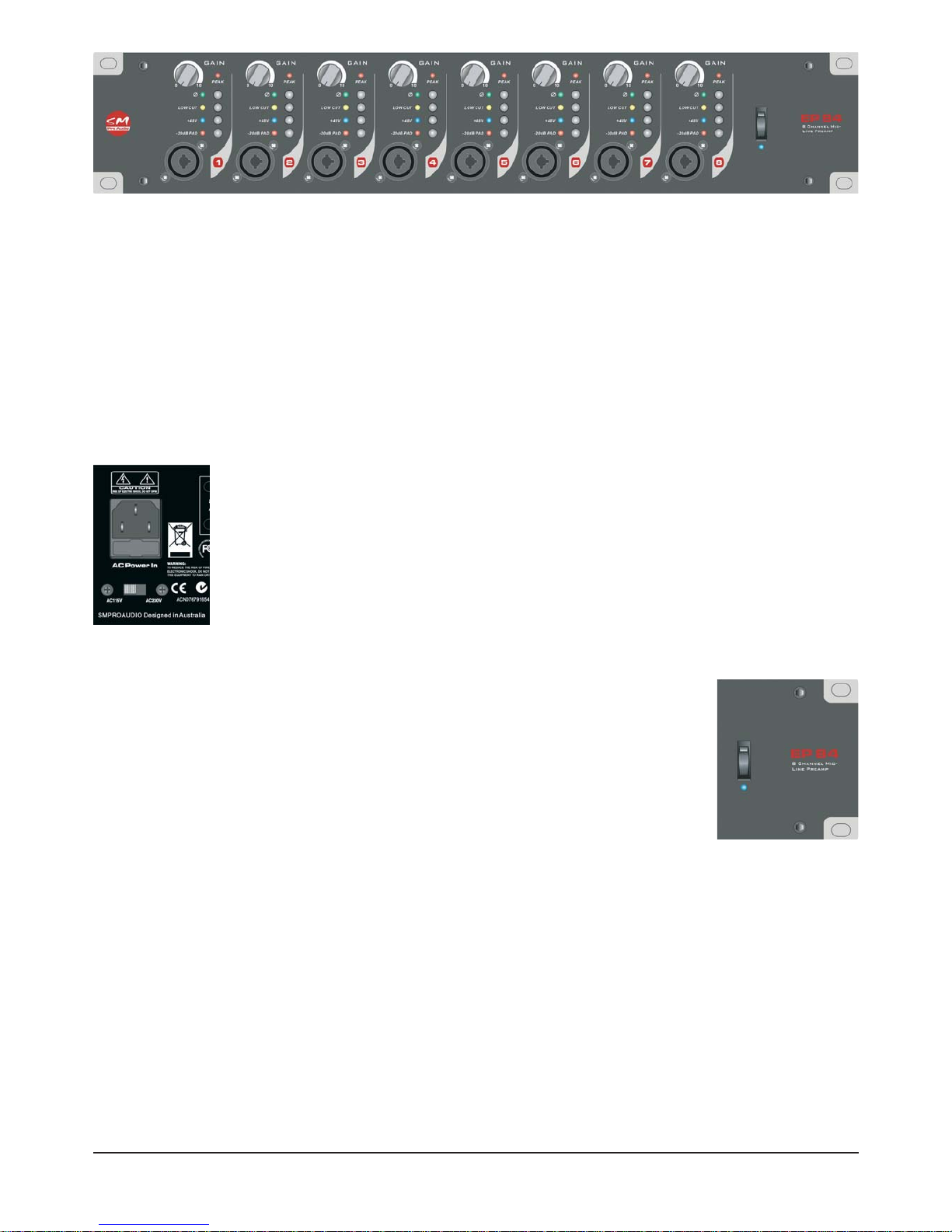
The EP84 has a professional internal power supply suitable for operation between
AC 110/115v – AC 220/230/240v. A voltage configuration switch on the left hand
side of the rear panel should be set to match the appropriate voltage of your mains
power supply . Simply slide the selector switch with your finger or a small flat-blade
screwdriver to either the 110v or 220v position to configure the unit accordingly.
To connect the EP84 to your mains power source simply connect the included standard IEC mains power cable to the EP84’s three (3) pin power connector socket.
Power on/off switch & LED power indicator
The EP84’s power switch can be found on the right hand side of the front panel.
To enable power to the EP84 or ‘turn on” simply place the power on/off switch
into the down position. The LED power indicator will illuminate to indicate the
EP84’s operational state as ‘on’ and ready for operation.
To power down or ‘turn off’ the EP84, simply place the power on/off switch into
the up position. The LED power indicator will not illuminate to indicate the
EP84’s operational state as ‘off’.
* It’s always good practice to protect your ears, and other audio equipment by taking appropriate
care when powering up any audio equipment. Being aware of your gain structure, and performing
a structured power up sequence with your equipment will help to avoid unexpected audio signals
bursts. It’s a good idea to power up devices in sequence from the start of the signal chain to the
end of the signal chain (EP84 -> recording device -> power amplifier/active monitors).
EP84 front panel
Page 7
7
Installation - Front Panel Controls
3.4 Audio Connections
Analog Inputs
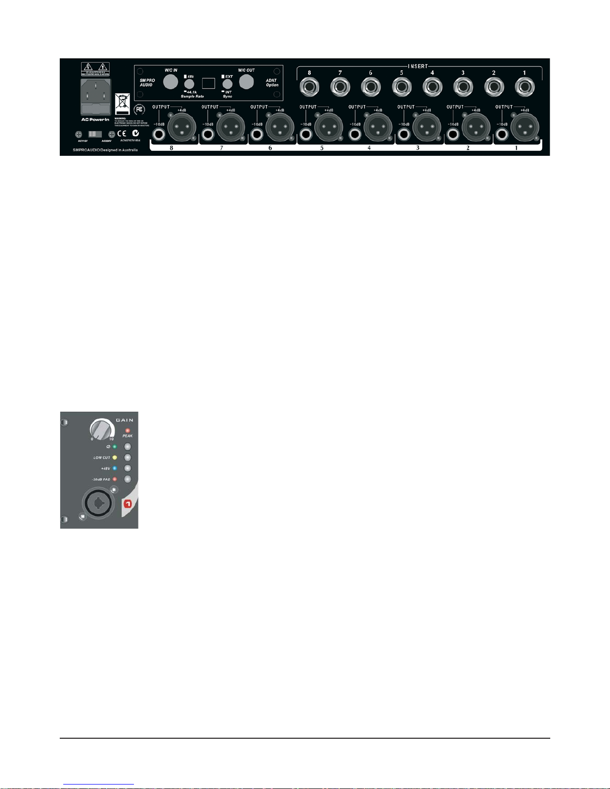
8 x combo (XLR & TS) input connectors can be found on the front panel. These are the direct analog inputs to the EP84’s 8 individual preamplifier modules. Input your audio source material via
either XLR or ¼” TS cable connectors.
Analog outputs
Both balanced +4dB XLR and unbalanced -10dB ¼” TS analog output connectors are provided for
each of the eight (8) preamplifier channels. Individual output levels can be controlled via the associated channels rotary gain control encoder on the front panel.
Insert Points
Each channel of the EP84 features a ¼” TRS insert connector. Typically, inserts are useful when
integrating additional outboard equipment (noise gates, expanders, compressors, etc.) in-line with
your audio source material. By using a stereo 1/4” TRS audio insert cable you can insert external
devices directly into the signal path of any of the eight audio channels.
4. FRONT PANEL CONTROLS & INDICATORS
4.1 Independent (8x) rotary preamplifier gain controls
Each channel features a rotary gain control for variable adjustment of the desired
pre-amplifier level. 60dB of variable gain is available per channel. Clockwise rotation increases the gain, whereas anti-clockwise rotation decreases the gain.
* Always begin using the EP84 with all gain controls set to the minimum value.
This way you can increase each channel gain gradually to the desired level without experiencing possible unwanted and unexpected loud signal surprises to both
you and the rest of your audio equipment!
4.2 Independent (8x) -20dB PAD switches
A-20dB P AD switch is provided for each channel to allow a twenty (20) decibel gain reduction of the
incoming signal if desired/required. When enabled the corresponding -20dB P AD LED will illuminate.
* This function is useful when connecting extremely "hot" signals. Excessive signal input levels can
overdrive the EP84’s pre-amplifier input stage resulting in unwanted signal distortion. The PAD
switch allows -20dB of gain attenuation/reduction to compensate for this situation prior to finer preamplifier gain adjustment.
4.3 Independent (8x) phantom power +48v switches
Each channel of the EP84 features a phantom power switch to facilitate enabling or disabling of
48v of continuous power supply to the channel. When enabled the corresponding phantom power
LED will illuminate.
EP84 rear panel
Page 8

8 Front Panel Controls - Application
* Phantom power is a voltage distribution system utilizing standard microphone cable. It is useful
(and often required) for powering condenser microphones connected to your audio system. If any
of your microphones require phantom power, simply enable the corresponding channels phantom
power switch to activate a constant 48v power supply.
4.4 Independent (8x) 80Hz low-cut (high-pass) filter switches
The EP84’s eight (8) low-cut (high-pass) filter switches enable and disable each channels respective 80Hz high-pass filter. Engaging this filter effectively removes low frequency “rumble” and other
unwanted noise by attenuating the signal dB below 80Hz. When enabled the corresponding lowcut LED will illuminate.
* The low-cut (high-pass) filter feature is useful in eliminating low frequency noise such floor rumble often picked up through microphone stands.
4.5 Independent (8x) phase reversal switches
Each channel features a phase reverse switch for reversing the phase of the audio signal 180
degrees. When enabled the corresponding phase reversal LED will illuminate.
* Phase cancellation can be a serious problem during the recording process. Two out of phase
sound waves that are summed together will cause some level of phase cancellation resulting in
less amplitude, severe tonal variations, and a distorted perceived overall quality of the sound. This
is especially of concern when recording two microphones within close proximity. In this instance,
activating the phase reverse switch on one of the microphone channels will help avoid phase cancellation issues.
The phase reverse switch is also extremely handy when used to correct inverted XLR pin wiring
configurations.
4.6 Independent (8x) peak indicator LED’s
Each channel features a peak light LED indicator. This momentarily indicates when the input signal strength has reached optimum input level.
* A continuously illuminated peak LED indicates you have surpassed optimum input level and distortion of the respective channels audio signal will occur. It’s time to adjust your gain structure!
5. APPLICATION
5.1 General use of the EP84
Four simple stages:
Evaluate your application and make decisions
- Firstly, you need to know what you are trying to pre-amplify. It maybe a single microphone signal, multiple microphone signals, or line level signal that requires strengthening. What types of
microphones are going to be used? Do the microphones require phantom power? Will low frequency sound waves need to be minimized? Is there the possibility of phase cancellation issues
arising? These types of questions must be answered if you are to correctly configure the EP84
for successful operation and performance. Once you have a good idea what you are trying to
achieve, you can make the necessary connections, and configure the EP84’s channel settings
with confidence.
Page 9

Make the necessary connections
- Connect your desired source signals to the EP84 via the front panel COMBO connectors (either
XLR or ¼” jack connector).
- If you would like to insert an external processor (ie. Compressor, EQ, etc) in the channels audio
signal path, connect the outboard device using a standard 1’4” TRS insert cable.
- Make the necessary connections from the corresponding channel outputs on the rear of the EP84
to your desired destination inputs (Mixer, recorder, etc). You can choose between either the XLR
balanced +4dB outputs or the unbalanced -10dB line level 1.4” jack outputs. Both outputs carry signal simultaneously.
Configure your channel settings and gain structure appropriately
- Set all your gain controls to minimum. This is the best place to start prior to adjustment of all your
settings.
- Enable phantom power per channel as required. Typically, condenser microphones that do not
have a power supply or battery will require phantom power. Dynamic microphones or line level signals from a keyboards output will not require phantom power. Each respective channels phantom
power LED will illuminate to indicate the phantom power status as “enabled”.
- Enable the low-cut filter per channel if desired. If you decided that low-cut filtering was desirable
simply depress the respective channels low-cut filter switch. Each respective channels low-cut filter LED will illuminate to indicate the filter status as “enabled”.
- Enable the phase reverse function per channel as required. This is especially important when
using multiple microphones in close proximity. If you require the signal to be phase inverted,
depress the phase reverse switch for the appropriate channel. Each respective channels phase
reverse LED will illuminate to indicate the phase reverse status as “enabled”.
- With the channel gain set to minimum, raise the rotary gain control slowly to reach the desired
input level. Agood input level will illuminate the peak LED briefly on very strong input signals only.
Continuous peak LED illumination indicates an overloaded distorted signal and should be adjusted
accordingly to a more appropriate level.
- If a continuously overloaded channels input gain cannot be reduced sufficiently with the rotary
gain control alone, the -20 dB PAD switch will be required to compensate. With a -20dB reduction
in gain attenuating the signal, you will now have a greater ability to set an appropriate gain structure with the rotary gain control.
- Setting levels on the pre-amp itself is important, however it is equally important to check the
incoming level at the inputs of your destination device (mixer, DAW recorder, etc.).
5.3 PR8IIA - Optional ADAT output module
The PR8IIAis an optional output module that can be fitted to the EP84 to provide pristine 24 bit digital conversion of your analog preamplifier to an ADAT digital format stream. Perfect for use with
ADAT compatible mixers, multi-track recorders, ADAT PC audio cards, or other professional ADAT
compatible devices, the PR8IIA upgrades your EP84 to fit seamlessly into the digital world.
Many of today’s computer based digital recording interfaces
feature a mixture of both analog and digital inputs and outputs. Often systems may only be able to input 8 analog
sources to the system simultaneously. Additional inputs may
be provided in the form of an 8 channel digital ADAT format
input. This is where a unit like the EP84 fitted with the PR8IIA
module really shines. Simply connect the ADAT output of the PR8IIA to the ADAT input on your audio
interface to achieve another 8 channels of pristine input to your system. The PR8IIAoffers internal or
external sync selectors, word clock I/O connections, and a sample rate selector switch (44.1/48kHz).
Image of PR8IIA above is subject to change.
9
Application
Page 10

Note: Both analog outputs from the EP84 and the PR8IIA’s ADAT digital output function simultaneously.
Enhance the front end of any ADAT compatible multi-track digital recording system with the PR8IIA.
Ask your dealer for more information.
6. SPECIFICATIONS
MIC INPUTS
Connector: XLR on COMBO
Type: Balanced
Impedance: 47K Ohms
Min sensitivity: -60 dB
Peak input level: +9.5 dB
LINE INPUTS
Connector: ¼” on COMBO
Type: Balanced
Impedance: 47K
Min sensitivity: -35dB
Peak input level: +32 dB
AUDIO INSERTS
Type: ¼” TRS insert connector
OUTPUT
Connector: ¼” TS jack, XLR
Type: unbalanced, balanced
Impedance: 600 Ohms
Peak output level: +23dB
Frequency response: 20Hz- 20KHz 0dB- -0.5dB
Distortion: 0.005%
S/N: > 105dB
Crosstalk rejection: >120dB @1KHz; -20dB input
Max Gain: 60dB
POWER
Type: Internal 110v-220v
SM Pro Audio is constantly striving to maintain the highest professional standards. Modifications
may be made over time to improve the performance and operation of this unit. As such, specifications and appearance may differ from those listed or shown.
10
Specifications
Page 11

11
Warranty
7. WARRANTY
7.1 WARRANTY CARD &/OR WEBSITE REGISTRATION
To be protected by this warranty the purchaser of the product must complete an SM Pro Audio product registration procedure.
Product registration is available via two methods:
- Complete and return the enclosed warranty card within 14 days of the date of purchase to SM Pro
Audio (see address below).
- Complete an online product registration form at the SM Pro Audio website. www.smproaudio.com
7.2 WARRANTY
- SM Pro Audio warrants the mechanical and electronic components of this product to be free of
defects in material and workmanship for a period of one (1) year from the original date of purchase.
SM Pro Audio will at its sole discretion either repair or replace the product if any defects occur that
are not caused by normal wear or inappropriate use within the warranty period.
- This warranty does not apply if the product has been damaged by negligence, non-authorized modifications, accident, abuse, misuse, misapplication, or as a result of unauthorized service other than
performed by that of SM Pro Audio’s service department.
- All freight charges incurred for transport of justified warranty claims are at the buyer's expense.
All other warranty claims other than those indicated above are excluded.
7.3 HOW TO REQUEST A RETURN AUTHORIZATION NUMBER
To obtain warranty service, the purchaser must call SM Pro Audio during normal business hours
before returning the product (Tel.: +61 3 9555 8081). An SM Pro Audio representative will discuss any issues with you over the telephone and then issue a return authorization number if
deemed appropriate.
Please ship original shipping cartons along with your return authorization number to the following
address:
SM Pro Audio
Service Department
Warehouse 25
Roberna Business Park
26-28 Roberna St
Moorabbin 3189
Melbourne, Victoria
Australia
Page 12

7.4 WARRANTY REGULATIONS
- Warranty can only be serviced when accompanying proof of purchase is provided. Dealers invoice
and date stamp required.
- SM Pro Audio will endeavor to repair or replace any product under the terms of this warranty within 30 days of receipt of the product at SM Pro Audio.
- Modifications performed in order to comply with any applicable technical or safety standards in any
country which is not the country for which the product was originally developed and manufactured
shall not be considered a defect in materials or workmanship. SM Pro Audio shall not be held
responsible for any costs incurred or resulting from any such modification whether performed correctly or not.
- This warranty does not cover defects of parts caused by normal operational wear. These parts are
typically switches, knobs, and other similar components.
Product damage caused by the following conditions are not covered by this warranty:
- Operation of the unit in a way that does not comply with the safety regulations applicable in the
country where the product is used.
- Damages or defects caused by conditions beyond the control of SM Pro Audio.
7.5 WARRANTY TRANSFERABILITY
This warranty is non transferable and available exclusively to the original purchaser.
7.6 DAMAGE CLAIMS
Failure of SM Pro Audio to provide proper warranty service does not entitle the purchaser to
claim further damages. SM Pro Audio’s liability shall in no way exceed the invoiced value of the
product.
7.7 OTHER WARRANTY RIGHTS
This warranty does not exclude or limit any statutory rights provided by national law.
12
Warranty
Page 13

The information contained in this manual is subject to change without notice.
ALL RIGHTS RESERVED © 2006 SM Pro Audio
SM Pro Audio
Service Department
Warehouse 25
Roberna Business Park
26-28 Roberna St
Moorabbin 3189
Melbourne, Victoria
Australia
PH- +61 3 9555 8081
FAX- +61 3 9555 8083
13
Legal Notice
 Loading...