

Page 1
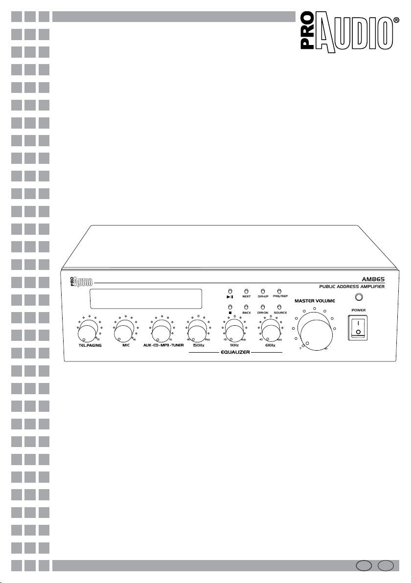
AM865
PA amplifiers
Manuale Utente
User Manual
I EN
Page 2

Music & Lights S.r.l. si riserva ogni diritto di elaborazione in qualsiasi forma delle presenti istruzioni per l’uso.
Al ne di migliorare la qualità dei prodotti, la Music&Lights S.r.l. si riserva la facoltà di modicare, in
qualunque momento e senza preavviso, le speciche menzionate nel presente manuale di istruzioni.
Tutte le revisioni e gli aggiornamenti sono disponibili nella sezione 'Manuali' sul sito www.musiclights.it
In order to improve the quality of products, Music&Lights S.r.l. reserves the right to modify the
La riproduzione - anche parziale - per propri scopi commerciali è vietata.
All rights reserved by Music & Lights S.r.l. No part of this instruction manual may be.
Reproduced in any form or by any means for any commercial use.
characteristics stated in this instruction manual at any time and without prior notice.
All revisions and updates are available in the ‘manuals’ section on site www.musiclights.it
REV.004-03/12
Page 3

I
AM865
EN
3
INDICE
Sicurezza
Avvertenze generali
Attenzioni e precauzioni per l’installazione
Informazioni generali
1 Descrizione e speciche tecniche
1. 1 Introduzione
1. 2 Caratteristiche tecniche
1. 3 Elementi di comando e collegamenti
2 Funzioni e impostazioni
2. 1 Alimentazione
2. 2 Funzionamento
2. 3 Impostazione dei volumi
3 Collegamenti
3. 1 Collegamento diusori
3. 2 Collegamento microfono
3. 3 Collegamento USB
3. 4 Collegamento altra apparecchiatura audio
3. 5 Terminali di controllo manuale della priorità
3. 6 Music on hold
Speciche tecniche
Criteri generali per installazione di sistemi di
sonorizzazione
4
5
6
7
7
8
11
11
11
12
13
13
13
13
13
14
15
INDEX
Safety
General instruction
Warning and precautions for xtures
General information
1 Description and technical specication
1. 1 Introduction
1. 2 Technical specications
1. 3 Operating elements and connections
2 Function and setting
2. 1 Power supply
2. 2 Operation
2. 3 Adjusting the volume
3 Connections
3. 1 Connecting speakers
3. 2 Connecting microphones
3. 3 USB connection
3. 4 Connecting other audio equipment
3. 5 Manual Priority terminals
3. 6 Music on hold
Technical data
General criteria for installation of sound systems
4
5
6
7
7
8
11
11
11
12
13
13
13
13
13
14
15
Certicato di garanzia
CONTENUTO DELL’IMBALLO:
• Amplicatore AM865
• Cavo di alimentazione
• Manuale utente
Warranty
PACKING CONTENT:
• Amplier AM865
• Main cable
• User manual
Tutte le speciche possono essere variate senza alcuna notica.
Design and specications are subject to change without notice.
Page 4

4
Prima di eettuare qualsiasi
operazione con l’unità, leggere
con attenzione questo manuale:
contiene informazioni importanti
riguardo l’installazione, l’uso e la
SICUREZZA
I
ATTENZIONE!
manutenzione dell’unità.
AM865
SAFETY
EN
WARNING!
Before carrying out any operations with
the unit, read carefully this instruction
manual and keep it with care for
future reference. It contains important
information about the installation,
usage and maintenance of the unit.
Avvertenze generali
• I prodotti a cui questo manuale si riferisce sono
conformi alle Direttive della Comunità Europea
e pertanto recano la sigla .
• Il dispositivo funziona con pericolosa tensione di
rete (230V~). Non intervenire mai al suo interno
al di fuori delle operazioni descritte nel presente
manuale; esiste il pericolo di una scarica elettrica.
• È obbligatorio eettuare il collegamento ad
un impianto di alimentazione dotato di una
eciente messa a terra (apparecchio di Classe
I secondo norma EN 60598-1). Si raccomanda,
inoltre, di proteggere le linee di alimentazione
dell’unità dai contatti indiretti e/o cortocircuiti
verso massa tramite l’uso di interruttori
dierenziali opportunamente dimensionati.
• Le operazioni di collegamento alla rete di
distribuzione dell’energia elettrica devono
essere eettuate da un installatore elettrico
qualicato. Vericare che frequenza e tensione
della rete corrispondono alla frequenza ed alla
tensione per cui l’unità è predisposta, indicate
sulla targhetta dei dati elettrici.
• L’unità non per uso domestico solo per uso
professionale.
• Evitare di utilizzare l’unità:
- in luoghi soggetti ad eccessiva umidità;
- in luoghi soggetti a vibrazioni, o a possibili urti;
- in luoghi a temperatura superiore ai 45°C o
inferiori a 2°C.
• Evitare che nell’unità penetrino liquidi
inammabili, acqua o oggetti metallici.
• Non smontare e non apportare modiche
all’unità.
• Tutti gli interventi devono essere sempre e
solo eettuati da personale tecnico qualicato.
Rivolgersi al più vicino centro di assistenza
tecnica autorizzato.
• Se si desidera eliminare il dispositivo
denitivamente, consegnarlo per lo
smaltimento ad un’istituzione locale per il
riciclaggio.
General instructions
• The products referred to in this manual
conform to the European Community
Directives and are therefore marked with .
• The unit is supplied with hazardous network
voltage (230V~). Leave servicing to skilled
personnel only. Never make any modications
on the unit not described in this instruction
manual, otherwise you will risk an electric
shock.
• Connection must be made to a power supply
system tted with ecient earthing (Class I
appliance according to standard EN 60598-1).
It is, moreover, recommended to protect the
supply lines of the units from indirect contact
and/or shorting to earth by using residual
current devices appropriately sized.
• The connection to the main network of
electric distribution must be carried out by
a qualied electrical installer. Check that the
main frequency and voltage correspond to
those the unit is designed for, as given on the
electrical data label.
• This unit is not for home use, only professional
applications.
• Never use the xture under the following
conditions:
- in places subject to excessive humidity;
- in places subject to vibrations or bumps;
- in places with temperature above 45°C or
below 2°C.
• Make certain that no inammable liquids,
water or metal objects enter the xture.
• Do not dismantle or modify the xture.
• All work must always be carried out by
qualied technical personnel. Contact the
nearest sales point for inspection or contact
the manufacturer directly.
• If the unit has to be put out of operation
denitively, take it to a local recycling plant
for a environmentally safe disposal.
Page 5

I
AM865
EN
5
Attenzione e precauzione per l’installazione
• Questo prodotto in combinazione con altoparlanti può essere capace di produrre livelli
sonori che possono causare perdite d’udito
permanenti. Si raccomanda di evitare l’esposizione ad alti livelli sonori o livelli non confortevoli per periodi di tempo lunghi.
• Evitare di installare l’unità in prossimità di fonti
di calore.
• Se il dispositivo dovesse trovarsi ad operare
in condizioni dierenti da quelle descritte nel
presente manuale, potrebbero vericarsi dei
danni; in tal caso la garanzia verrebbe a decadere. Inoltre, ogni altra operazione potrebbe
provocare cortocircuiti, incendi, scosse elettriche, rotture ect.
• Collocare o posizionare il prodotto in modo
che non ci siano ostruzioni alla sua propria
ventilazione e dissipazione di calore. Non installare in uno spazio limitato.
• Il livello di ingresso dell’amplicatore non deve
mai superare la sensibilità segnata.
• Non collegare l’uscita di un amplicatore
nell’entrata di un altro. Non collegare in serie
o in parallelo le uscite di un amplicatore con
quelle di un altro.
• Assicurarsi che il segnale sia connesso correttamente all’entrata dell’amplicatore e che esso
sia nella giusta modalità di funzionamento.
• Spegnere l’amplicatore prima di disconnettere il cavo di alimentazione dalla rete.
• Prima di iniziare qualsiasi operazione di manutenzione o pulizia disconnettere l’unità dalla
rete di alimentazione.
Warning and precautions for xtures
• This product in combination with loudspeakers, may be capable of producing dangerous
sound levels that could cause permanent
hearing loss. Do not operate for a long period
of time at high volume level or at a level that is
uncomfortable.
• Do not install the xture near sources of heat.
• If this device will be operated in any way dier-
ent to the one described in this manual, it may
suer damages and the guarantee becomes
void. Furthermore, any other operation may
lead to dangers like short circuit, burns, electric shock, ect.
• The xture must be located in a place where
a proper ventilation or thermal dissipation
is not impeded. Do not install the xture in a
conned space.
• The output level of the amplier must never
exceed the marked sensitivity.
• Do not link the output of any amplier channel back into another channel ‘s input. Do not
parallel or series connect an amplier’s output
with any other amplier’s output.
• Make sure that the signal is correctly connected to the amplier’s input channel and set to
the proper input mode.
• Please turn o the power switch before pulling
o the power cord.
• Before starting any maintenance work or
cleaning the unit, cut o power from the main
supply.
Page 6

6
I
AM865
EN
INFORMAZIONI GENERALI
Spedizioni e reclami
Le merci sono vendute “franco nostra sede” e
viaggiano sempre a rischio e pericolo del distributore/cliente. Eventuali avarie e danni dovranno essere contestati al vettore. Ogni reclamo per
imballi manomessi dovrà essere inoltrato entro 8
giorni dal ricevimento della merce.
Garanzie e resi
L’amplicatore AM865 è coperto da garanzia in base
alle vigenti normative.
Sul sito www.musiclights.it è possibile consultare
il testo integrale delle “Condizioni Generali di
Garanzia”. Si prega, dopo l’acquisto, di procedere
alla registrazione del prodotto sul sito
www.musiclights.it.
In alternativa il prodotto può essere registrato
compilando e inviando il modulo riportato alla
ne del manuale. A tutti gli eetti la validità
della garanzia è avallata unicamente dalla
presentazione del certicato di garanzia.
Music & Lights constata tramite verica sui resi
la difettosità dichiarata, correlata all’appropriato
utilizzo, e l’eettiva validità della garanzia;
provvede quindi alla riparazione dei prodotti,
declinando tuttavia ogni obbligo di risarcimento
per danni diretti o indiretti eventualmente
derivanti dalla difettosità.
GENERAL INFORMATION
Shipments and claims
The goods are sold “ex works” and always travel at
the risk and danger of the distributor.
Eventual damage will have to be claimed to the
freight forwarder. Every claim for broken packs
will have to be forwarded within 8 days from the
reception of the goods.
Warranty and returns
The guarantee covers the AM865 amplier in
compliance with existing regulations. You can nd
the full version of the “General Guarantee Conditions”
on our web site www.musiclights.it.
Please remember to register the piece of
equipment soon after you purchase it, logging
on www.musiclights.it. The product can be also
registered lling in and sending the form available
on your guarantee certicate. For all purposes,
the validity of the guarantee is endorsed solely on
presentation of the guarantee certicate.
Music & Lights will verify the validity of the claim
through examination of the defect in relation
to proper use and the actual validity of the
guarantee. Music & Lights will eventually provide
replacement or repair of the products declining,
however, any obligation of compensation
for direct or indirect damage resulting from
faultiness.
Page 7

I
AM865
EN
7
-1- DESCRIZIONE E SPECIFICHE
TECNICHE
1.1 Introduzione
Robusti e versatili, gli amplicatori PA di ProAudio
orono potenza, semplicità d’installazione e massima essibilità d’uso nei sistemi Public Address.
Dotati di circuito di protezione contro il sovraccarico ed il corto circuito delle uscite, garantiscono
massima durata ed adabilità riducendo al minimo i costi di manutenzione. Queste unità dispongono, inoltre, di tutte le funzioni, i controlli e le
connessioni necessarie per l’utilizzo a tensione o
ad impedenza costante nei sistemi di sonorizzazione multi-canale e multi-zona.
1.2 Caratteristiche tecniche
Amplicatore mixer con sintonizzatore FM e lettore MP3/USB integrato
• Progettato per la miscelazione e trasmissione
di annunci microfonici e/o programmi musicali
in sistemi P.A.
• Uscite a impedenza costante (4-16Ohm) e a
tensione costante (70/100V)
• Ingressi: 2 Mic, 1 Aux/CD con selettore, 1 USB
• Sintonizzatore FM e lettore MP3/USB integrati
• Funzione priorità
• Equalizzatore a tre bande
• Controlli indipendenti per segnali in ingresso
-1- DESCRIPTION AND TECHNICAL
SPECIFICATIONS
1.1 Introduction
Sturdy and versatile ProAudio PA loudspeakers
are characterized by a strong professional quality
power, easiness of installation and deep exibility,
making them fully adapted in any Public Address.
Equipped with a protection circuit against short
circuits between output terminals and overloads,
they guarantee a maximum duration and reliability reducing maintenance costs. Thanks to their
dedicated functions, controls and connections,
ProAudio® loudspeakers can be used by voltage
or by constant acoustic impedance in the multichannels and multi-zone audio systems.
1.2 Technical specications
Mixer - amplier with FM tuner and MP3/USB
player
• Designed for mixing and broadcasting announcements and music in PA systems
• Impedance constant outputs (4-16Ohm) and
constant voltage outputs (70/100V)
• Inputs: 2 Mic, 1 Aux/CD selectable, 1 USB
• Built-in FM tuner and MP3/USB player
• Priority function
• 3 band EQ controls
• Independent level controls for input signals
Page 8
8
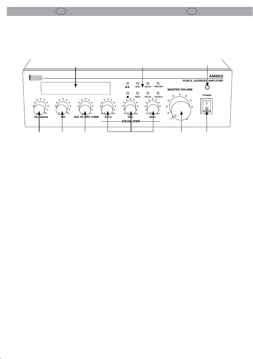
1.3 Elementi di comando e collegamenti 1.3 Operating elements and connections
I
AM865
EN
89
1 2 3 5 6
PANNELLO FRONTALE FRONT PANEL
1. POTENZIOMETRO DI VOLUME SEGNALE TELEFONICO
2. POTENZIOMETRO DI VOLUME MICROFONO
3. POTENZIOMETRO DI VOLUME INGRESSO AUX/
CD/MP3/TUNER
4. EQUALIZZATORE
5. MASTER: potenziometro di volume che regola
il livello generale del segnale proveniente dai
singoli ingressi. Normalmente le migliori prestazioni si ottengono con la manopola posizionata a circa ¾ della corsa.
6. INTERRUTTORE POWER
7. INDICATORE ON DI ACCENSIONE: quando acceso, l’amplicatore è alimentato correttamente.
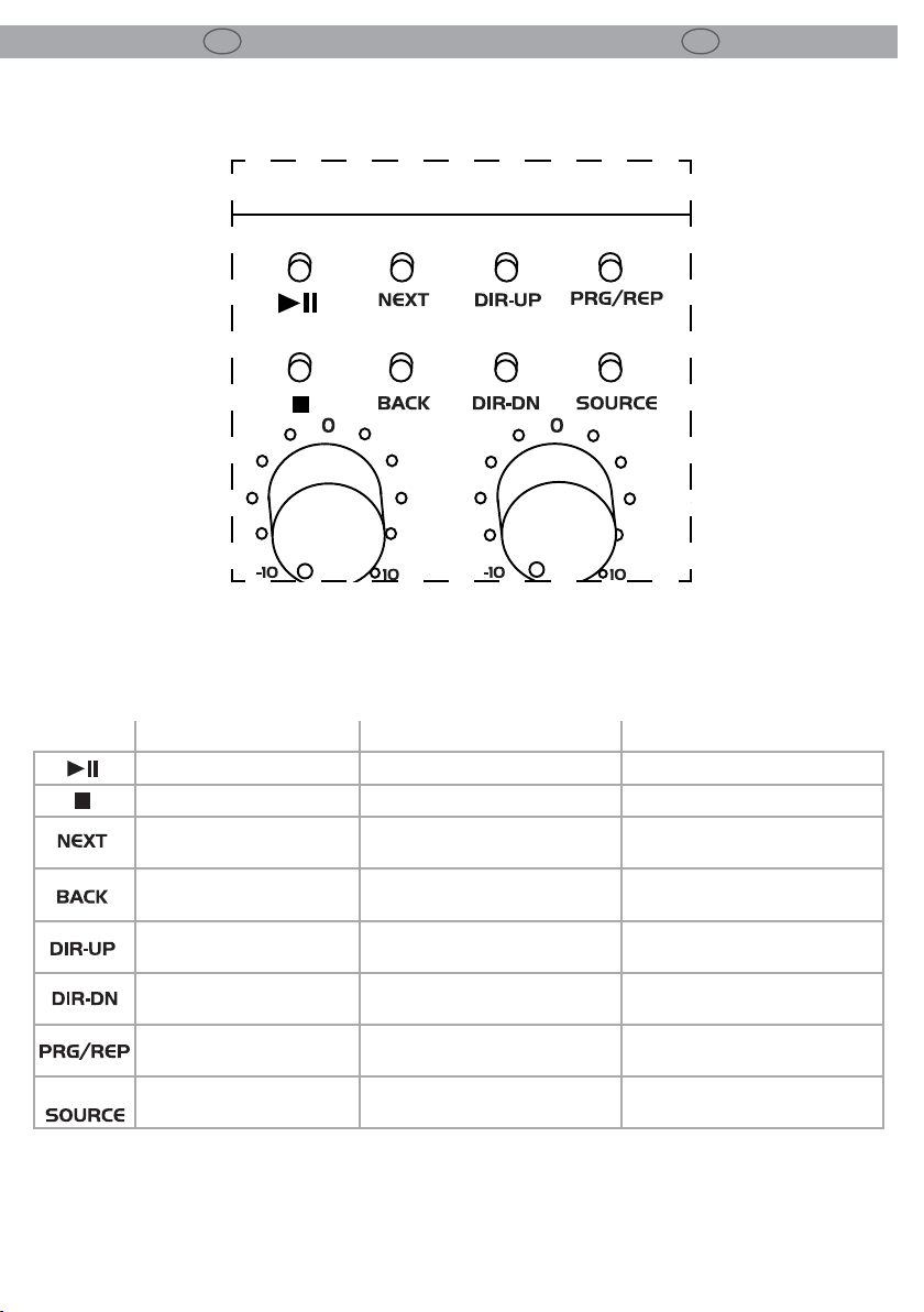
8. PULSANTI PER LA MODALITA’ MP3/FM/AM:
vedi tabella pag. 9 (g 2)
9. DISPLAY LCD
4
Fig.1
1. VOLUME POTENTIOMETER TELEPHONE SIGNAL
2. VOLUME POTENTIOMETER MICROPHONE
3. VOLUME POTENTIOMETER ENTRY AUX/CD/
MP3/TUNER
4. EQUALIZER
5. MASTER: volum potentiometer to adjust the
master outpit level coming from each input.
In normal conditions the best performance is
obtained with the volume knob set approximately at ¾ of maximum value.
6. POWER SWITCH
7. POWER INDICATOR: when this indicator is on,
the amplier main power supply is working.
8. BUTTONS FOR THE MODE MP3/FM/AM: see table pag. 9 (g 2)
9. DISPLAY LCD
7
Page 9
I
AM865
Fig.2
EN
9
PULSANTE MP3 FM AM
Play/Pause Invalid/non valido Invalid/non valido
Stop Invalid/non valido Invalid/non valido
Next le/
File successivo
Last le/Ultimo le
Next folder/
Cartella successiva
Last folder/
Ultima cartella
Invalid/non valido
Switch to FM/
Passaggio alla modalità FM
Ricerca ne in avanti o autoricerca
Ricerca ne indietro o autoricerca
Next channel/
Canale successivo
Next channel/
Canale precedente
Up ne-turning or autoserch/
Up ne-turning or autoserch/
Save channels/
Memorizzare canale
Switch to AM/
Passaggio alla modalità AM
Next channel/
Canale successivo
Next channel/
Canale precedente
Up ne-turning or autoserch/
Ricerca ne in avanti o autoricerca
Up ne-turning or autoserch/
Ricerca ne indietro o autoricerca
Save channels/
Memorizzare canale
Switch to AUX1/
Passaggio alla modalità AUX1
Page 10
10
I
AM865
EN
202124 2223
11 14 15 16 17 18 19
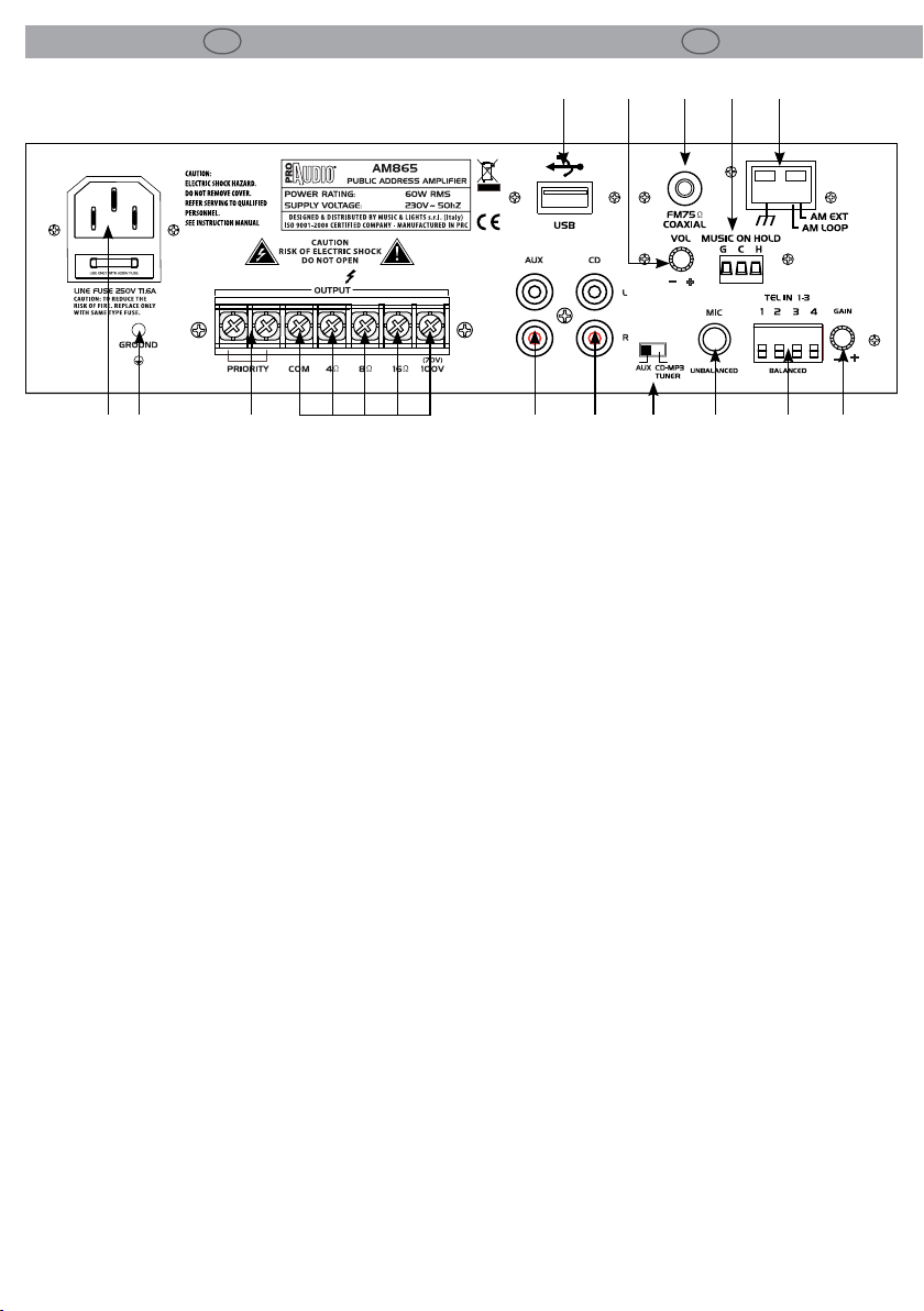
PANNELLO POSTERIORE REAR PANEL
10. SPINA DA PANNELLO VDE: per il collegamento
ad una presa di rete (230~/50-60Hz) tramite il
cavo di rete in dotazione. Sotto la presa si trova
il portafusibile.
11. GND POINT: per la messa a terra del dispositivo
12. MORSETTO A VITE “PRIORITY”
13. MORSETTI A VITE PER COLLEGAMENTI:
- Uscita diretta COM (Comune) per collegamento diusore o gruppi di diusori.
- Morsetto a vite per collegamento diusori o
gruppi di diusori con impedenza 4 Ω.
- Morsetto a vite per collegamento diusori o
gruppi di diusori con impedenza 8 Ω.
- Morsetto a vite per collegamento diusori o
gruppi di diusori con impedenza 16 Ω.
- Morsetto a vite per collegamento diusore
con ingresso audio 70 V.
- Morsetto a vite per collegamento diusore
con ingresso audio 100 V.
14. INGRESSO RCA: per AUX
15. INGRESSO RCA: per CD
16. COMMUTATORE PER SELEZIONARE LE DIVERSE
MODALITA’: AUX/CD/MP3/TUNER
17. PRESA JACK 6,3 mm: ingresso MIC sbilanciato
18. INGRESSO TELEFONICO
19. GAIN: per impostare la sensibilità d’ingresso
dei canali
20. ANTENNA AM
21. MUSIC ON HOLD: link in AUX con regolazione
del volume
22. ANTENNA FM
23. Potenziometro del volume dell’uscita MUSIC
ON HOLD
24. COLLEGAMENTO PER DISPOSITIVO USB
12 1310
Fig.3
10. VDE PANEL PLUG: this plug is connected to the
socket (230~/50-60Hz) through the supplied
mains cable. The mains fuse support is located
beyond the mains plug.
11. GND POINT: grounding the xture to the earth
12. MANUAL PRIORITY TERMINALS
13. Direct OUTPUT COM( Common): screw terminal for a speaker or a speaker group.
- screw terminal for connection of speaker or a
speaker group with a impedance of 4 Ω
- screw terminal for connection of speaker or a
speaker group with a impedance of 8 Ω
- screw terminal for connection of speaker or a
speaker group with a impedance of 16 Ω
- screw terminal for 70V speaker
- screw terminal for 70V speaker
14. RCA INPUT: for AUX
15. RCA INPUT: for CD
16. AUX/CD/MP3/TUNER: selector switch
17. 6,3 JACK PLUG: for MIC input unbalanced.
18. TELEPHONE PAGING CONNECTOR
19. GAIN: for adjusting the input sensitivity
20. AM ANTENNA
21. MUSIC ON HOLD: link in AUX with volume control
22. FM ANTENNA
23. Potentiometer output volume MUSIC ON
HOLD
24. USB CONNECTOR
Page 11

I
AM865
EN
11
-2- FUNZIONI E IMPOSTAZIONI
2.1 Alimentazione
Inserire la spina del cavo di alimentazione in una
presa di rete (230V~/50-60Hz).
2.2 Funzionamento
Seguire questa procedura per l’accensione
dell’amplicatore:
- Posizionare sul minimo i CONTROLLI DI LIVELLO dell’amplicatore.
- Accendere l’unità mediante l’INTERRUTTORE
POWER (6). L’INDICATORE DI ACCENSIONE (7)
posto sopra il tasto dovrebbe illuminarsi.
2.3 Impostazioni dei volumi
- Agire sui CONTROLLI DI LIVELLO dell’unità no
a raggiungere il volume necessario.
- Regolare il livello generale del segnale proveniente dai singoli ingressi attraverso AUX1/CD/
MP3/TUNER (3) dell’amplicatore.
- Regolare il livello generale del segnale proveniente dai singoli ingressi attraverso il MASTER
(5) dell’amplicatore.
- È possibile che sia necessario aggiustare ancora una volta il volume dei segnali d’ingresso
con i relativi CONTROLLI DI LIVELLO ; è preferibile non cambiare la posizione del regolatore
MASTER (5).
- Portare i CONTROLLI DI LIVELLO degli ingressi
non utilizzati sullo zero.
- Se necessario impostare i toni con L’EQUALIZZATORE (4).
Nota: Per gli ingressi posti nel pannello posteriore, la sensibilità all’ingresso può essere impostata
con i regolatori GAIN. Se un controllo del livello
deve essere aperto moltissimo o quasi chiuso per
ottenere il rapporto di volume richiesto rispetto
agli altri ingressi, conviene modicare la sensibilità d’ingresso con il relativo regolatore GAIN.
-2- FUNCTIONS AND SETTINGS
2.1 Power supply
Connect the supplied main cable to a socket
(230V~/50-60Hz).
2.2 Operation
Use the following procedure when turning on
your amplier:
- Turn down the LEVEL CONTROLS of the amplier.
- Switch on the amplier with the POWER
SWITCH (6). The POWER ON INDICATOR (7)
should be brighten.
2.3 Adjusting the volume
- Turn up the LEVEL CONTROLS on the amplier
until the desired loudness.
- Adjust the general level coming from each
input with AUX1/CD/MP3/TUNER/ (3) of the
amplier.
- Adjust the general level coming from each input with the MASTER (5) of the amplier.
- It may be necessary to adjust once again the
volume of the input signals with the corresponding LEVEL CONTROLS ; Do not change
the control MASTER (5).
- Turn the LEVEL CONTROLS of the inputs not
used to zero.
- If necessary adjust the sound with the controls
EQUALIZER (4).
Note: For the inputs on the rear panel, the input sensitivity can be adjusted with the controls
GAIN. If a level control must be turned up very
much or almost be closed to obtain the desired
volume ratio to the other inputs, modify the input
sensitivity with the corresponding control GAIN.
Page 12
12
I
AM865
EN
-3- COLLEGAMENTI
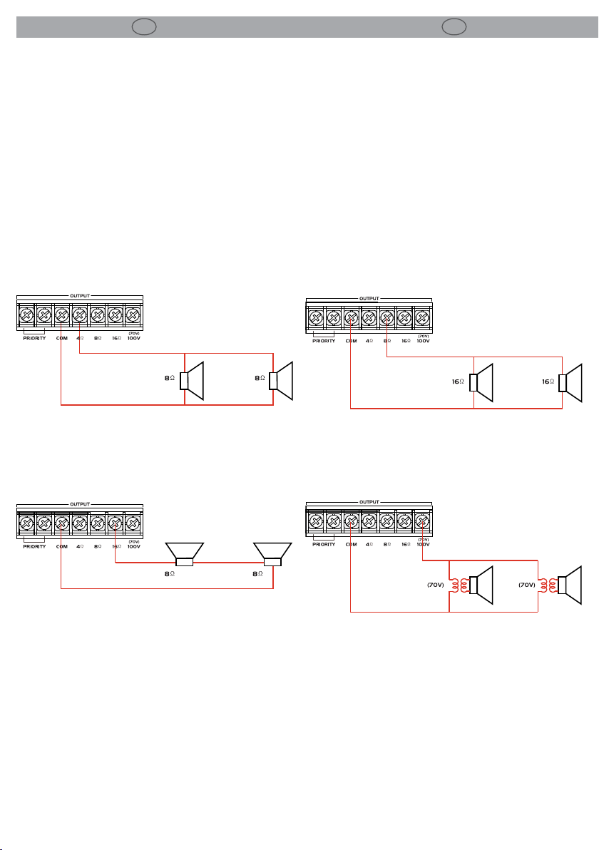
3.1 Collegamento diusori
Si possono collegare diusori con ingresso audio
70 V e 100 V o gruppi di diusori con impedenza
totale non inferiore a 4 Ω attraverso i morsetti a
vite (16/17/18/19), posti sul pannello posteriore.
Prestare sempre attenzione alla corretta polarità
(g.4).
Attenzione: mai connettere i terminali di impedenza costante e tensione costante contemporaneamente!
Impedenza 4 Ω
-3- CONNECTIONS
3.1 Connecting speakers
It’s possible to connect 70 V, 100 V speakers or
speaker group with a total impedance of 4 Ω as a
minimum to the screw terminals (16/17/18/19) on
the rear panel of the amplier. When connecting
the speakers, always observe the correct polarity
(g.4).
Caution: never use both the Low-Z and Hi-Z terminals at the same time.
Impedenza 8 Ω
Impedenza 16 Ω
Voltage 70V
Fig.4
Page 13

I
AM865
EN
13
3.2 Collegamento microfono
Si può collegare un microfono mediante la presa
Jack 6,3 mm sbilanciate poste sul pannello posteriore dell’amplicatore. L’ingresso prioritario è
ottenuto cortocircuitando i morsetti a vite “PRIORITY”(12).
Nell’eettuare il collegamento posizionare a zero
il relativo controllo di livello dell’amplicatore.
3.3 Collegamento USB
E’ possibile collegare dispositivi con interfaccia
USB tramite la porta d’ingresso posizionata sulla
parte frontale dell’amplicatore (5).
si consiglia di connettere il dispositivo USB prima
di accendere l’amplicatore.
Se l’amplicatore è acceso, il dispositivo USB
connesso viene automaticamente innescando
l’autoplay e l’impostazione predenita è un ciclo
completo
3.4 Collegamento altra apparecchiatura audio
Il collegamento di una sorgente audio, si può effettuare utilizzando gli ingressi RCA AUX e CD, posti nel pannello posteriore dell’amplicatore.
Inoltre è possibile collegare un ulteriore amplicatore utilizzando l’uscita MUSIC ON HOLD (21)
con la gestione indipendente del volume (23)
3.5 Terminali di controllo manuale della priorità
Cortocircuitando i terminali PRIORITY vengono
messi in mute i segnali di ingresso AUX, CD dando
priorità alle funzioni dell’ingresso telefonico e del
microfono.
3.6 Music on hold
Questa uscita fornisce il segnale musicale al sistema telefonico per le chiamate in attesa di risposta.
In tal caso è necessario che il sistema telefonico
sia dotato di un ingresso dedicato.
Il segnale di uscita deve essere collegato ai morsetti G e H. Il livello del volume è regolato tramite
il potenziometro (23) posto accanto ai terminali
nel pannello posteriore dell’amplicatore.
3.2 Connecting microphones
It’s possible to connect a microphone with 6,3
mm Jack plug unbalanced on the rear panel of
the amplier. Priority entrance is obtained by
shorting the screw terminals “PRIORITY” (12).
When connecting a microphone, turn down the
corresponding level control of the amplier.
3.3 USB connection
Can be connect devices withe a USB interface
through the door located on the front panel of
the amplier (5).
It is should to connect the USB device befor turning on the amplier.
If the amplier is turned on, the USB device is connected automatically triggering the autoplay and
the default setting is in full loop.
3.4 Connecting other audio equipment
The connection of other audio equipment is possible through the RCA input for AUX and CD on
the rear panel of the amplier.
It’s possible connect an additional amplier
output using the MUSIC ON HOLD (21) with indipendent control of volume (23).
3.5 Manual Priority terminals
Shortcircuiting the terminals PRIORITY are muted
signals AUX and CD, giving priority to the microphone and telephone input functions
3.6 Music on hold
This output gives the musical signal to the telephone system for calls to be answered. In this
case it is necessary that the telephone system is
equipped with a dedicated input.
The output signal must be connected to the terminals G and H. The volume level is adjusted with
a potentiometer (23) located next to the terminals on the rear panel of the amplier.
Page 14

14
I
AM865
EN
SPECIFICHE TECNICHE TECHNICAL SPECIFICATION
TECHNICAL DATA AM865
RMS Output power
Constant impedance output
Constant voltage output
Input Connectors
Output Connectors
Frequency response
Distortion (THD)
Tone controls
Input volume controls
Power Supply
Rack Units
Dimensions (WxHxD)
60W
4-16Ohm
70/100V
Din balanced for Mic1, 6.3mm jack for Mic2 , 2xRCA for
AUX / 2xRCA for CD, USB
Output on terminal board
100/20.000Hz (±3dB)
<0.5% (1KHz)
150 Hz, 1KHz, 6kHz (±10dB)
Mic1, Mic2, AUX/CD/MP3/Tuner
230V AC (±5%)
2U (19” standard rack)
90x270x260mm
Weight
5.8kg
Page 15

I
AM865
EN
15
CRITERI GENERALI PER INSTALLAZIONE DI
SISTEMI DI SONORIZZAZIONE
Premessa
Questa guida rappresenta una rapida introduzione
ai criteri per l’installazione di un sistema di sonorizzazione a tensione costante o a impedenza costante.
L’impianto dovrà comunque essere realizzato da personale qualicato, il quale dovrà valutare le esigenze
dell’utilizzatore e le caratteristiche ambientali degli
spazi da sonorizzare, selezionare i diusori in funzione dell’ambiente e del tipo di messaggio da trasmettere (es. parlato/musica), identicare il modello di amplicatore idoneo a pilotare il complesso dei diusori
e dotato di un numero di ingressi adeguato, valutare
il collegamento per i diusori e determinare la sezione dei cablaggi.
L’impianto a tensione costante
In tema di selezione e collegamento dei diusori, è
necessario valutare se utilizzare normali diusori a
4/8/16Ohm o diusori con trasformatore. La decisione in genere è condizionata dalla destinazione
dell’impianto (supermercato, discoteca, pub, abitazione, ...) e dal numero di diusori da utilizzare. I
diusori a tensione costante vengono impiegati generalmente per tutte quelle situazioni in cui sia necessario installare numerosi diusori di bassa potenza per una distribuzione audio omogenea e a basso
volume. Il classico esempio è quello dall’aereoporto
o del supermercato. In queste situazioni di solito vengono infatti posizionati numerosi altoparlanti a breve
distanza tra loro, con un volume tale da non disturbare ma con una frequenza tale da coprire tutta l’area
desiderata con la medesima pressione sonora.
GENERAL CRITERIA FOR INSTALLATION OF
SOUND SYSTEMS
Introduction
This guide represents a quick introduction to the criteria for the installation of a sound system at constant
voltage or constant impedence.
A sound system must be made by qualied personnel only, who must evaluate the needs of the user
and the environmental characteristics of the spaces
to be covered, select the speakers according to the
spaces and the type of message to be broadcasted
(ie: speech / music ), identify the suitable amplier
model to drive the complex of all the speakers and
having an adequate number of inputs, evaluate the
proper connection for the speakers and determine
the section of the wiring.
Constant voltage systems
In terms of selection of speakers and their connection it’s necessary to evaluate whether to use normal
speakers with 4/8/16Ohm impedance or speakers
with transformer. The decision is usually inuenced
by the destination of the system (supermarket, disco
, pub, house, ...) and by the number of speakers to
employ. Constant voltage speakers are normally used
into situations where it is necessary to install several
speakers with low power to get a homogeneous distribution of audio and overall low volume. The classic example is the sound installation in airports or
supermarkets. In these situations several speakers are
usually placed within a short distance between them,
normally a volume low enough to not disturb and a
frequency covering the entire area with same sound
pressure.
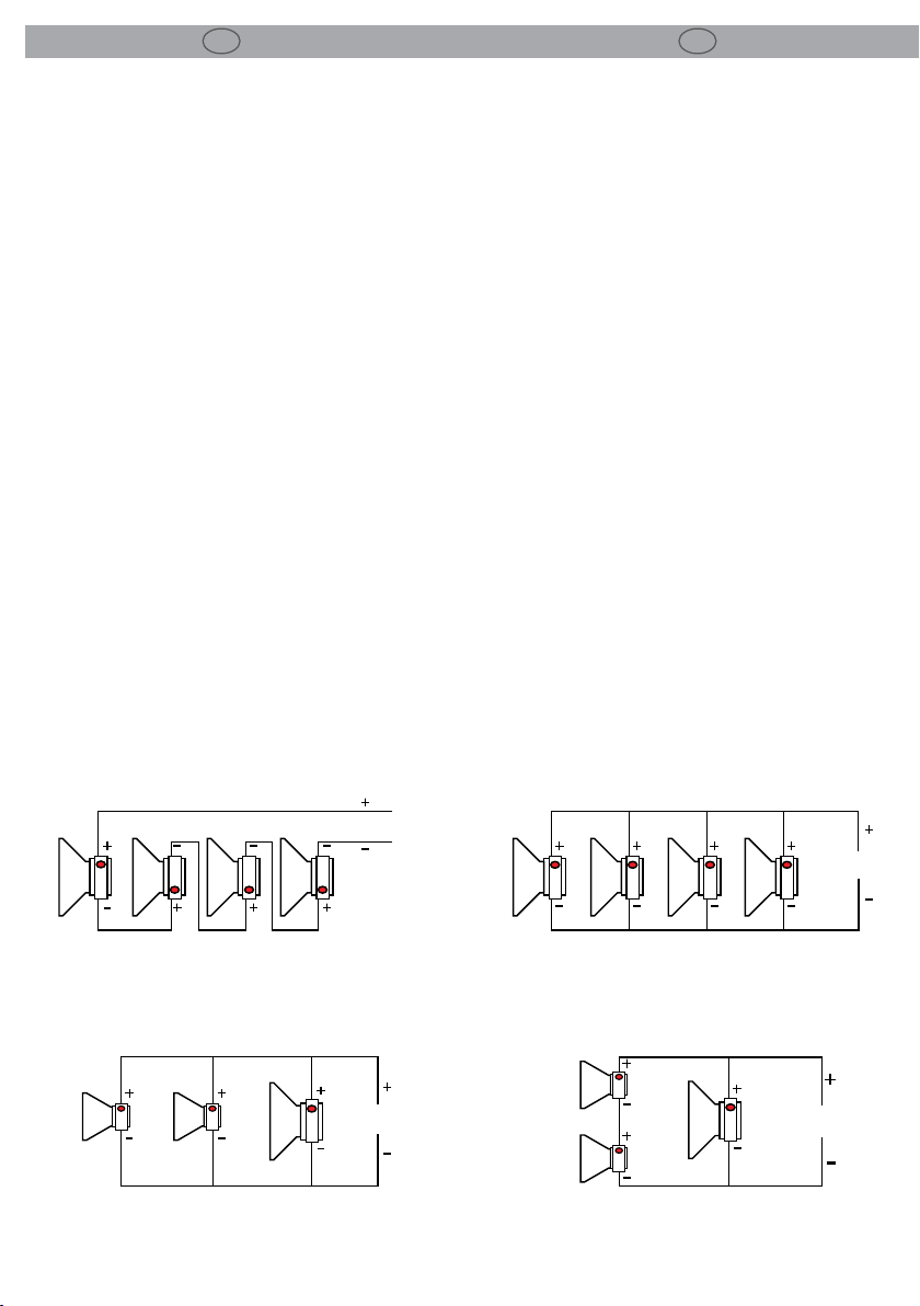
Dierenze tra impianti 4/8/16 Ohms e impianti a
tensione costante
Gli impianti a 4/8/16Ohm sono condizionati da problemi di impedenze:
• diusori collegati in “serie” sommano le loro impedenze (es. 4Ohm + 4Ohm = 8Ohm)
• diusori collegati in “parallelo” dividono l’impedenza
(es. 8Ohm // 8Ohm = 4Ohm)
Nella gure successive sono riportati alcuni esempi di
collegamento: serie, parallelo, serie + parallelo. E’ riportata anche la potenza applicabile in base al tipo di
altoparlanti e alle impedenze di ciascuno. In prossimità degli altoparlanti sono riportate le corrette polarità.
Gli impianti a tensione costante utilizzano invece diffusori muniti di trasformatore. Generalmente sono
congurabili su 2 o più potenze massime. In questo
Dierences between 4/8/16 Ohms systems
and constant voltage systems
The 4/8/16Ohm systems are aected by problems of
impedances:
• speakers connected in “series” mode add their
impedance (example: 4Ohm + 4Ohm = 8Ohm)
• speakers connected in “parallel” mode divide their
impedance (example: 8Ohm / / = 8Ohm 4Ohm)
In the following pictures nd a few examples
of connections: series, parallel, series + parallel. Also the applicable power is reported according to type and impedance of each speaker.
Please note polarity indicated for each speaker.
Constant voltage systems use speakers equipped
with transformer. Normally they can be congured
on 2 or more dierent maximum power levels. In this
Page 16
16
I
AM865
EN
tipo di impianto i conduttori utilizzati sono solo 2:
il nero va collegato al polo negativo (generalmente
contrassegnato da “0” o “COM”), il rosso va collegato
al morsetto desiderato (50V, 70V, 100V). I trasformatori di tutti i diusori andranno collegati a questi 2
soli conduttori avendo cura di rispettare le polarità
indicate.
Alcuni accorgimenti importanti da tenere in considerazione:
• La tensione selezionata sul trasformatore del diusore deve corrispondere a quella scelta sull’amplicatore.
• La somma delle potenze dei diusori non deve mai
superare la potenza dell’amplicatore.
• Per garantire una corretta riproduzione del segnale
audio, è importante che il collegamento sia “in fase”,
ovvero che il collegamento tra polarità positiva e
negativa dell’amplicatore coincida con le polarità
utilizzate sul trasformatore.
• E’ importante che i cavi abbiano una sezione adeguata: al crescere della lunghezza totale dell’impianto la sezione dei cavi dovrà crescere di conseguenza
per evitare distorsioni o perdite di segnale.
• I cavi per il collegamento dei diusori non devono essere passati insieme ad altri cavi di tipo elettrico o microfonico per evitare ronzii o inneschi di ogni genere.
• E’ importante utilizzare sempre cavi con conduttori
intrecciati
type of system only 2 conductors are employed: the
black one is connected to the negative terminal (usually marked by “0” or “COM”), the red one is connected
to one of the contacts (50V, 70V, 100V). The amplier
driving all speakers will be connected to such 2 wires
paying attention that right polarities are respected.
Please note that:
• Voltage selected on speaker transformer must
match the voltage selected on the amplier.
• Total sum of speakers power must not exceed
power of the amplier.
• To ensure a correct reproduction of the audio signal it is important to setup the connection with
no phase shifts: the connection between positive
and negative poles of the amplier must match
the polarity on speaker transformer.
• It is important that cables have an adequate section: increasing total length of the sound installation involves increasing of cable section to avoid
distortion or signal loss.
• Cables for connection of the speakers should be
passed separately from other electrical or microphone cables, to avoid ground loops or triggers
of any kind.
• It ‘s always important to use cables with twisted
wires
SERIES CONNECTION
16 Ohm 30W 16 Ohm 30W
PARALLEL CONNECTION
8 Ohm 60W
16 Ohm 120W4 Ohm 30W4 Ohm 30W 4 Ohm 30W 4 Ohm 30W
4 Ohm 120W
16 Ohm 30W 16 Ohm 30W 16 Ohm 30W 16 Ohm 30W
4 Ohm 120W
PARALLEL CONNECTION
4 Ohm 30W
4 Ohm 120W
4 Ohm 30W
8 Ohm 60W
SERIES + PARALLEL CONNECTION
Page 17

"
CERTIFICATO DI GARANZIA
GUARANTEE CERTIFICATE
Place Stamp Here
Arancare
Spett.le
Music&Lights S.r.l.
Via Appia Km 136.200
04020 Itri (LT) Italy
"
The guarantee covers the unit
in compliance with existing
regulations. You can nd the
full version of the “General
Il prodotto è coperto da garanzia
in base alle vigenti normative.
Sul sito www.musiclights.it è
possibile consultare il testo
Guarantee Conditions” on our
web site www.musiclights.it.
integrale delle “Condizioni
Generali di Garanzia”.
Abstract
General Guarantee Conditions
Estratto dalle
Condizioni Generali di Garanzia
piece of equipment soon after you
• Please remember to register the
procedere alla registrazione del
• Si prega, dopo l’acquisto, di
purchase it, logging on
www.musiclights.it. The product
can be also registered lling in and
prodotto sul sito www.musiclights.it.
In alternativa il prodotto può essere
registrato compilando e inviando il
sending the form available on your
guarantee certicate.
modulo riportato sul retro.
• Sono esclusi i guasti causati da
• Defects caused by inexperience
imperizia e da uso non appropriato
and incorrect handling of the
equipment are excluded.
eective if the equipment has
been tampered.
• The guarantee will no longer be
• The guarantee makes no provision
dell’apparecchio.
qualora l’apparecchio sia stato
manomesso.
• La garanzia non ha più alcun eetto
sostituzione dell’apparecchio.
• La garanzia non prevede la
for the replacement of the
equipment.
• External parts, loudspeaker,
parti esterne, gli altoparlanti, le
manopole, gli interruttori e le parti
• Sono escluse dalla garanzia le
handles, switches and removable
parts are not included in the
guarantee.
risks are responsibility of the
owner of the equipment.
• Transport costs and subsequent
asportabili.
conseguenti sono a carico del
possessore dell’apparecchio.
• Le spese di trasporto e i rischi
garanzia è avallata unicamente
• A tutti gli eetti la validità della
the guarantee is endorsed solely
on presentation of the guarantee
certicate.
• For all purposes, the validity of
dalla presentazione del certicato di
garanzia.
Page 18

FORM TO BE FILLED IN AND MAILED / CEDOLA DA COMPILARE E SPEDIRE FORM TO BE FILLED IN AND KEPT / CEDOLA DA COMPILARE E CONSERVARE
"
Purchased by / Acquistato da
Purchasing date
Data acquisto
del Rivenditore
ZIP CODE / C.A.P.
PROV.
CITY / CITTA’
ADDRESS / VIA N.
NAME / NOME
Dealer’s stamp
and signature
Timbro e rma
SURNAME / COGNOME
SERIAL N° / SERIE N°
MODEL / MODELLO
Purchased by / Acquistato da
Purchasing date
Data acquisto
del Rivenditore
ZIP CODE / C.A.P.
PROV.
CITY / CITTA’
ADDRESS / VIA N.
NAME / NOME
Dealer’s stamp
and signature
Timbro e rma
SURNAME / COGNOME
SERIAL N° / SERIE N°
MODEL / MODELLO
Page 19

Page 20

©2012 Music & Lights S.r.l.PROAUDIO è un brand di proprietà della Music & Lights S.r.l. PROAUDIO is a brand of Music & Lights S.r.l. company.
Music & Lights S.r.l. entertainment technologies
Via Appia Km 136,200 - 04020 Itri (LT) ITALY
tel. +39 0771 72190 fax +39 0771 721955
www.musiclights.it [email protected]
ISO 9001:2008
Certified Compa ny
 Loading...