

Page 1
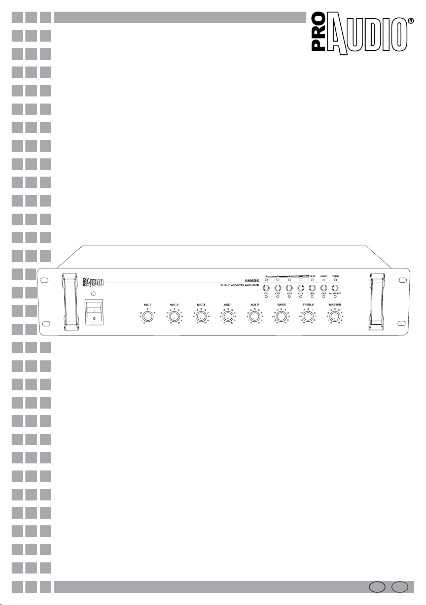
AM612/AM626
PA amplifiers
Manuale Utente
User Manual
I GB
Page 2

Music & Lights S.r.l. si riserva ogni diritto di elaborazione in qualsiasi forma delle presenti
istruzioni per l’uso. La riproduzione - anche parziale - per propri scopi commerciali è vietata.
REV.003-12/09
All rights reserved by Music & Lights S.r.l.. No part of this instruction manual may be
reproduced in any form or by any means for any commercial use.
Page 3

I
AM612/AM626
GB
3
INDICE
Sicurezza
Avvertenze generali
Attenzioni e precauzioni per l’installazione
Informazioni generali
1 Descrizione e speciche tecniche
1. 1 Introduzione
1. 2 Caratteristiche tecniche
1. 3 Elementi di comando e collegamenti
2 Funzioni e impostazioni
2. 1 Alimentazione
2. 2 Funzionamento
2. 3 Impostazione dei volumi
2. 4 Attivare le zone di sonorizzazione
2. 5 Funzioni di protezione
2. 6 Sistema di protezione termica
3 Collegamenti
3. 1 Collegamento altoparlanti
3. 2 Collegamento microfoni
3. 3 Collegamento altra apparecchiatura audio
Speciche tecniche
Brevi cenni di acustica
Certicato di garanzia
4
5
6
7
7
8
10
10
10
10
10
11
12
12
12
13
14
INDEX
Safety
General instruction
Warning and precautions for xtures
General information
1 Description and technical specication
1. 1 Introduction
1. 2 Technical specications
1. 3 Operating elements and connections
2 Function and setting
2. 1 Power supply
2. 2 Operation
2. 3 Adjusting the volume
2. 4 Activating the PA zones
2. 5 Reliability protection function
2. 6 Cooling system and thermal protection
3 Connections
3. 1 Connecting speakers
3. 2 Connecting microphones
3. 3 Connecting other audio equipment
Technical data
Brief notes on acoustics
Warranty
4
5
6
7
7
8
10
10
10
10
10
11
12
12
12
13
14
CONTENUTO DELL’IMBALLO:
• Amplicatore AM612/AM626
• Cavo di alimentazione
• Manuale utente
Tutte le speciche possono essere variate senza alcuna notica.
Design and specications are subject to change without notice.
PACKING CONTENT:
• Amplier AM612/AM626
• Main cable
• User manual
Page 4
4
Prima di eettuare qualsiasi
operazione con l’unità, leggere
con attenzione questo manuale:
contiene informazioni importanti
riguardo l’installazione, l’uso e la
SICUREZZA
I
ATTENZIONE!
manutenzione dell’unità.
AM612/AM626
SAFETY
GB
WARNING!
Before carrying out any operations with
the unit, read carefully this instruction
manual and keep it with care for
future reference. It contains important
information about the installation,
usage and maintenance of the unit.
Avvertenze generali
• I prodotti a cui questo manuale si riferisce sono
conformi alle Direttive della Comunità Europea
e pertanto recano la sigla .
• Il dispositivo funziona con pericolosa tensione di
rete (230V~). Non intervenire mai al suo interno
al di fuori delle operazioni descritte nel presente
manuale; esiste il pericolo di una scarica elettrica.
• È obbligatorio eettuare il collegamento ad
un impianto di alimentazione dotato di una
eciente messa a terra (apparecchio di Classe
I secondo norma EN 60598-1). Si raccomanda,
inoltre, di proteggere le linee di alimentazione
dell’unità dai contatti indiretti e/o cortocircuiti
verso massa tramite l’uso di interruttori
dierenziali opportunamente dimensionati.
• Le operazioni di collegamento alla rete di
distribuzione dell’energia elettrica devono
essere eettuate da un installatore elettrico
qualicato. Vericare che frequenza e tensione
della rete corrispondono alla frequenza ed alla
tensione per cui l’unità è predisposta, indicate
sulla targhetta dei dati elettrici.
• L’unità non per uso domestico solo per uso
professionale.
• Evitare di utilizzare l’unità:
- in luoghi soggetti ad eccessiva umidità;
- in luoghi soggetti a vibrazioni, o a possibili urti;
- in luoghi a temperatura superiore ai 45°C o
inferiori a 2°C.
• Evitare che nell’unità penetrino liquidi
inammabili, acqua o oggetti metallici.
• Non smontare e non apportare modiche
all’unità.
• Tutti gli interventi devono essere sempre e
solo eettuati da personale tecnico qualicato.
Rivolgersi al più vicino centro di assistenza
tecnica autorizzato.
• Se si desidera eliminare il dispositivo
denitivamente, consegnarlo per lo
smaltimento ad un’istituzione locale per il
riciclaggio.
General instructions
• The products referred to in this manual
conform to the European Community
Directives and are therefore marked with .
• The unit is supplied with hazardous network
voltage (230V~). Leave servicing to skilled
personnel only. Never make any modications
on the unit not described in this instruction
manual, otherwise you will risk an electric
shock.
• Connection must be made to a power supply
system tted with ecient earthing (Class I
appliance according to standard EN 60598-1).
It is, moreover, recommended to protect the
supply lines of the units from indirect contact
and/or shorting to earth by using residual
current devices appropriately sized.
• The connection to the main network of
electric distribution must be carried out by
a qualied electrical installer. Check that the
main frequency and voltage correspond to
those the unit is designed for, as given on the
electrical data label.
• This unit is not for home use, only professional
applications.
• Never use the xture under the following
conditions:
- in places subject to excessive humidity;
- in places subject to vibrations or bumps;
- in places with temperature above 45°C or
below 2°C.
• Make certain that no inammable liquids,
water or metal objects enter the xture.
• Do not dismantle or modify the xture.
• All work must always be carried out by
qualied technical personnel. Contact the
nearest sales point for inspection or contact
the manufacturer directly.
• If the unit has to be put out of operation
denitively, take it to a local recycling plant
for a environmentally safe disposal.
Page 5

I
AM612/AM626
GB
5
Attenzione e precauzione per l’installazione
• Questo prodotto in combinazione con altoparlanti può essere capace di produrre livelli
sonori che possono causare perdite d’udito
permanenti. Si raccomanda di evitare l’esposizione ad alti livelli sonori o livelli non confortevoli per periodi di tempo lunghi.
• Evitare di installare l’unità in prossimità di fonti
di calore.
• Se il dispositivo dovesse trovarsi ad operare
in condizioni dierenti da quelle descritte nel
presente manuale, potrebbero vericarsi dei
danni; in tal caso la garanzia verrebbe a decadere. Inoltre, ogni altra operazione potrebbe
provocare cortocircuiti, incendi, scosse elettriche, rotture ect.
• Collocare o posizionare il prodotto in modo
che non ci siano ostruzioni alla sua propria
ventilazione e dissipazione di calore. Non installare in uno spazio limitato.
• Il livello di ingresso dell’amplicatore non deve
mai superare la sensibilità segnata.
• Non collegare l’uscita di un amplicatore
nell’entrata di un altro. Non collegare in serie
o in parallelo le uscite di un amplicatore con
quelle di un altro.
• Assicurarsi che il segnale sia connesso correttamente all’entrata dell’amplicatore e che esso sia
nella giusta modalità di funzionamento.
• Spegnere l’amplicatore prima di disconnettere il cavo di alimentazione dalla rete.
• Prima di iniziare qualsiasi operazione di manutenzione o pulizia disconnettere l’unità dalla
rete di alimentazione.
Warning and precautions for xtures
• This product in combination with loudspeakers, may be capable of producing dangerous
sound levels that could cause permanent
hearing loss. Do not operate for a long period
of time at high volume level or at a level that is
uncomfortable.
• Do not install the xture near sources of heat.
• If this device will be operated in any way dier-
ent to the one described in this manual, it may
suer damages and the guarantee becomes
void. Furthermore, any other operation may
lead to dangers like short circuit, burns, electric shock, ect.
• The xture must be located in a place where
a proper ventilation or thermal dissipation
is not impeded. Do not install the xture in a
conned space.
• The output level of the amplier must never
exceed the marked sensitivity.
• Do not link the output of any amplier channel back into another channel ‘s input. Do not
parallel or series connect an amplier’s output
with any other amplier’s output.
• Make sure that the signal is correctly connected to the amplier’s input channel and set to
the proper input mode.
• Please turn o the power switch before pulling
o the power cord.
• Before starting any maintenance work or
cleaning the unit, cut o power from the main
supply.
Page 6

6
I
AM612/AM626
GB
INFORMAZIONI GENERALI
Spedizioni e reclami
Le merci sono vendute “franco nostra sede” e
viaggiano sempre a rischio e pericolo del distributore/cliente. Eventuali avarie e danni dovranno essere contestati al vettore. Ogni reclamo per
imballi manomessi dovrà essere inoltrato entro 8
giorni dal ricevimento della merce.
Garanzie e resi
Gli amplicatori AM612/AM626 sono coperti da
garanzia in base alle vigenti normative.
Sul sito www.musiclights.it è possibile consultare
il testo integrale delle “Condizioni Generali di
Garanzia”. Si prega, dopo l’acquisto, di procedere
alla registrazione del prodotto sul sito
www.musiclights.it.
In alternativa il prodotto può essere registrato
compilando e inviando il modulo riportato alla
ne del manuale. A tutti gli eetti la validità
della garanzia è avallata unicamente dalla
presentazione del certicato di garanzia.
Music & Lights constata tramite verica sui resi
la difettosità dichiarata, correlata all’appropriato
utilizzo, e l’eettiva validità della garanzia;
provvede quindi alla riparazione dei prodotti,
declinando tuttavia ogni obbligo di risarcimento
per danni diretti o indiretti eventualmente
derivanti dalla difettosità.
GENERAL INFORMATION
Shipments and claims
The goods are sold “ex works” and always travel at
the risk and danger of the distributor.
Eventual damage will have to be claimed to the
freight forwarder. Every claim for broken packs
will have to be forwarded within 8 days from the
reception of the goods.
Warranty and returns
The guarantee covers the AM612/AM626 ampliers
in compliance with existing regulations. You can
nd the full version of the “General Guarantee
Conditions” on our web site www.musiclights.
it. Please remember to register the piece of
equipment soon after you purchase it, logging
on www.musiclights.it. The product can be also
registered lling in and sending the form available
on your guarantee certicate. For all purposes,
the validity of the guarantee is endorsed solely on
presentation of the guarantee certicate.
Music & Lights will verify the validity of the claim
through examination of the defect in relation
to proper use and the actual validity of the
guarantee. Music & Lights will eventually provide
replacement or repair of the products declining,
however, any obligation of compensation
for direct or indirect damage resulting from
faultiness.
Le informazioni riportate in questo manuale sono
state attentamente controllate.
Music & Lights S.r.l. non si assume, tuttavia, responsabilità derivanti da eventuali inesattezze.
The information provided in this manual has been
carefully checked.
However Music & Lights S.r.l. is not responsible for
any possible inaccuracy.
Page 7

I
AM612/AM626
GB
7
-1- DESCRIZIONE E SPECIFICHE
TECNICHE
1.1 Introduzione
Robusti e versatili, gli amplicatori PA di ProAudio
orono potenza, semplicità d’installazione e massima essibilità d’uso nei sistemi Public Address.
Dotati di circuito di protezione contro il sovraccarico ed il corto circuito delle uscite, garantiscono
massima durata ed adabilità riducendo al minimo i costi di manutenzione. Queste unità dispongono, inoltre, di tutte le funzioni, i controlli e le
connessioni necessarie per l’utilizzo a tensione o
ad impedenza costante nei sistemi di sonorizzazione multi-canale e multi-zona.
1.2 Caratteristiche tecniche
Amplicatore mixer a 6 zone.
• Progettato per la miscelazione e trasmissione
di annunci microfonici e/o programmi musicali
in tutti i sistemi P.A.
• Uscite a impedenza costante (4-16 Ohm) e a
tensione costante (70,100 V).
• 7 ingressi: 3 Mic in, 2 stereo line, 2 emergency
input.
• Ingresso con funzione priorità ad attivazione
vocale a tre livelli.
• Uscita PRE-OUT RCA.
• Indicatore livello di uscita a LED.
• Controlli per bassi e alti.
• Sei zone selezionabili indipendentemente.
• Controlli indipendenti per segnali in ingresso.
• 2U 19” standard rack.
-1- DESCRIPTION AND TECHNICAL
SPECIFICATIONS
1.1 Introduction
Sturdy and versatile ProAudio PA loudspeakers
are characterized by a strong professional quality
power, easiness of installation and deep exibility,
making them fully adapted in any Public Address.
Equipped with a protection circuit against short
circuits between output terminals and overloads,
they guarantee a maximum duration and reliability reducing maintenance costs. Thanks to their
dedicated functions, controls and connections,
ProAudio® loudspeakers can be used by voltage
or by constant acoustic impedance in the multichannels and multi-zone audio systems.
1.2 Technical specications
6 zone Mixer/Amplier.
• Designed for broadcasting and mixing microphonic announcements and music in PA systems.
• Impedance constant outputs (4-16 Ohm) and
constant voltage outputs (70,100 V).
• 7 inputs: 3 Mic in, 2 stereo line, 2 emergency
input.
• Vocal activating 3 levels priority input.
• RCA PRE-OUT output.
• LED Vu meter.
• Bass and Treble EQ controls.
• Six independently selectable zones.
• Independent level controls for input signals.
• 2U 19” standard rack.
Page 8
8
I
AM612/AM626
GB
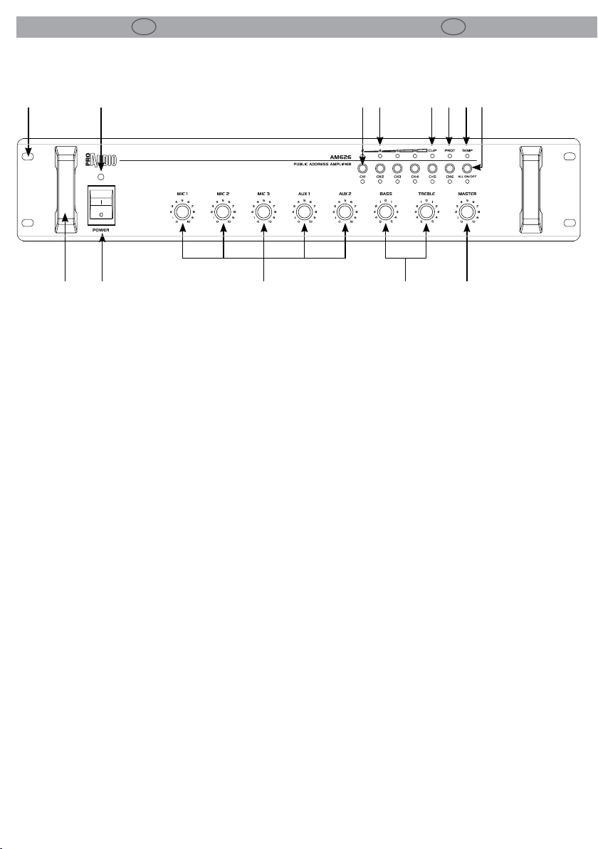
1.3 Elementi di comando e collegamenti 1.3 Operating elements and connections
1
4
. . . . . .
3 5 6 7
2
9
-
-
-
-
-
11 128
10
-
-
.
.
-
-
-
13
PANNELLO FRONTALE FRONT PANEL
1. FORI DI FISSAGGIO per il montaggio rack
2. MANIGLIE.
3. INTERRUTTORE POWER.
4. INDICATORE ON DI ACCENSIONE: quando acceso,
l’amplicatore è alimentato correttamente.
5. CONTROLLI DI LIVELLO ROTATIVI DEI SEGNALI
DI INGRESSO: consentono di regolare il livello del
segnale per gli ingressi 1 - 5.
- CONTROLLO DI LIVELLO DEL Mic 1: questo potenziometro controlla il livello di ingresso del Mic 1.
- CONTROLLO DI LIVELLO DEL Mic 2: questo potenziometro controlla il livello di ingresso del Mic.
- CONTROLLO DI LIVELLO DEL Mic 3: questo potenziometro controlla il livello di ingresso del Mic 3.
- CONTROLLO DI LIVELLO DEL AUX 1: questo potenziometro controlla il livello di ingresso del AUX 1.
- CONTROLLO DI LIVELLO DEL AUX 2: questo potenziometro controlla il livello di ingresso del AUX 2.
Il range di controllo si estende da 0 ~ 10.
6. BASS/TREBLE:
controlli di tono che permettono di
modicare la timbrica del suono. Con la manopola
in posizione (0) non avviene alcuna alterazione
timbrica.
7. MASTER: potenziometro di volume che regola il
livello generale del segnale proveniente dai singoli
ingressi. Normalmente le migliori prestazioni si
ottengono con la manopola posizionata a circa ¾
della corsa.
8. SELETTORI DI ZONA 1 - 6: attivano o escludono
il canale dell’amplicatore relativo alla zona
desiderata.
9. INDICATORI DI LIVELLO IN USCITA: consentono di
1. MOUNTING HOLES for xing the rack.
2. HANDLES.
3. POWER SWITCH.
4. POWER ON INDICATOR: when this indicator is on,
the amplier main power supply is working.
5. ROTARY LEVEL CONTROL OF INPUT SIGNALS:
they permit the adjustment of the inputs 1 - 5 signals.
- Mic 1 LEVEL CONTROL: this potentiometer just
controls Mic 1 level.
- Mic 2 LEVEL CONTROL: this potentiometer just
controls Mic 2 level.
- Mic 3 LEVEL CONTROL: this potentiometer just
controls Mic 3 level.
- AUX 1 LEVEL CONTROL: this potentiometer just
controls AUX 1 level.
- AUX 2 LEVEL CONTROL: this potentiometer just
controls AUX 2 level.
Gain control range: 0 ~ 10.
6. BASS/TREBLE: tone controls. When the knob is in
the position (0) no signal equalization is applied.
7. MASTER: volume potentiometer to adjust the
master output level coming from each input.
In normal conditions the best performance is
obtained with the volume knob set approximately
at ¾ of maximum value.
8. 1 - 6 ZONE SELECTORS: they switch on or switch
o the channel of the amplier for the desired zone.
9. OUTPUT LEVEL INDICATORS: allow to monitor
the output level of the respective channels of the
amplier.
10. CLIP INDICATOR: the led lights up indicates a
visualizzare il livello di uscita dell’amplicatore.
Page 9
I
AM612/AM626
GB
9
10. INDICATORE DI “CLIP”: l’accensione del led indica
la presenza di distorsione.
11. INDICATORE DI PROTEZIONE: si accende quando
l’amplicatore va in modalità di protezione.
12. INDICATORE DI SURRISCALDAMENTO: Il led TEMP
si accende quando la temperatura dei transistor
supera un valore di sicurezza.
13. SELETTORE ALL ZONE ON/OFF: Attiva o esclude
tutte le zone contemporaneamente.
14
20 21 22 23
15 16 17 18 19 24 25
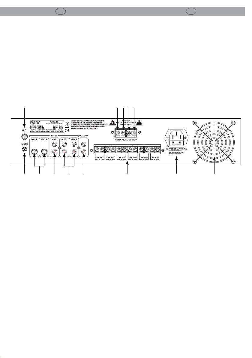
PANNELLO POSTERIORE REAR PANEL
sound distortion.
11. PROTECTION INDICATOR: when this indicator is
illuminated, the amplier is in protection status.
12. OVER-HEAT INDICATOR: the TEMP LED lights up
when transistors temperature exceeds 95°C.
13. ALL ZONE ON/OFF SELECTOR: switch on or switch
o all zone at the same time.
26
14. PRESA JACK 6,3 mm ingresso prioritario Mic 1.
15. INTERRUTTORE “MUTE” per Mic 1.
16. PRESA JACK 6,3 mm ingresso Mic 2 e Mic 3.
17. INGRESSO RCA per EMC (Emergency).
18. INGRESSO RCA per AUX1 e AUX2.
19. USCITA RCA Line out.
20. USCITA diretta COM (Comune). Morsetto a vite
per collegamento diusore o gruppi di diusori.
21. USCITA diretta 4 ~ 16 Ω. Morsetto a vite per
collegamento diusori o gruppi di diusori con
impedenza 4 ~ 16 Ω.
22. USCITA diretta 70 V. Morsetto a vite per
collegamento diusore con ingresso audio 70 V.
23. USCITA diretta 100 V. Morsetto a vite per
collegamento diusore con ingresso audio 100 V.
24. USCITA ZONA 1 - 6. Morsetti a vite per collegamento
diusori con ingresso audio 100 V.
25. SPINA DA PANNELLO VDE per il collegamento
ad una presa di rete (230V~/50-60Hz) tramite il
cavo rete in dotazione. Sotto la presa si trova il
portafusibile.
26. PRESE DI VENTILAZIONE: aperture per uscita
usso d’aria da non ostruire.
14. 6,3 mm JACK PLUG for Mic 1 priority input.
15. Mic 1 “MUTE” SWITCH.
16. 6,3 mm JACK PLUG for Mic 2 and Mic 3 input.
17. RCA INPUT for EMC (Emergency).
18. RCA INPUT for AUX1 and AUX2.
19. RCA OUTPUT Line out.
20. Direct OUTPUT COM( Common). Screw terminal
for a speaker or a speaker group.
21. Direct OUTPUT 4 ~ 16 Ω. Screw terminal for a
connection of speaker or a speaker group with a
impedance of 4 ~ 16 Ω .
22. Direct OUTPUT. Screw terminal for 70 V speakers.
23. Direct OUTPUT. Screw terminal for 100 V speakers.
24. ZONE 1- 6 OUTPUT. Screw terminal for 100 V
speakers.
25. VDE PANEL PLUG: this plug is connected to the
socket (230V~/50-60Hz) through the supplied
mains cable. The mains fuse support is located
below the mains plug.
26. VENTILATION OPENINGS: the openings let the air
ow in. Do not obstruct them.
Page 10

10
I
AM612/AM626
GB
-2- FUNZIONI E IMPOSTAZIONI
2.1 Alimentazione
Inserire la spina del cavo di alimentazione in una
presa di rete (230V~/50-60Hz).
2.2 Funzionamento
Seguire questa procedura per l’accensione
dell’amplicatore:
- Posizionare sul minimo i CONTROLLI DI LIVELLO (5) e il MASTER (7) dell’amplicatore.
- Accendere l’unità mediante l’INTERRUTTORE
POWER (3). L’INDICATORE DI ACCENSIONE (4)
posto sopra il tasto dovrebbe illuminarsi.
2.3 Impostazioni dei volumi
- Agire sui CONTROLLI DI LIVELLO (5) dell’unità
no a raggiungere il volume necessario.
- Regolare il livello generale del segnale proveniente dai singoli ingressi attraverso il MASTER
(7) dell’amplicatore. In caso di sovrapilotaggio, nella visualizzazione del livello (9) si accende il LED CLIP (10). In questo caso ridurre il
volume con il regolatore MASTER.
- È possibile che sia necessario aggiustare ancora una volta il volume dei segnali d’ingresso
con i relativi CONTROLLI DI LIVELLO (5); è preferibile non cambiare la posizione del regolatore MASTER (7).
- Portare i CONTROLLI DI LIVELLO (5) degli in-
gressi non utilizzati sullo zero.
- Se necessario impostare i toni con controlli
BASS/TREBLE (6).
2.4 Attivare le zone di sonorizzazione
1. Con i tasti SELETTORI DI ZONA 1 - 6 (8) attivare
le zone da sonorizzare. Come controllo si accendono i LED delle zone attivate.
2. Per avvisi destinati a tutte le zone, premere il
tasto SELETTORE ALL ZONE (13). Il volume delle zone è quello impostato con il MASTER (7).
2.5 Funzioni di protezione
Gli amplicatori AM612/AM626 sono equipaggiati con una serie di ecacissime protezioni, contro
sovraccarico, surriscaldamento e cortocircuito,
-2- FUNCTIONS AND SETTINGS
2.1 Power supply
Connect the supplied main cable to a socket
(230V~/50-60Hz).
2.2 Operation
Use the following procedure when turning on
your amplier:
- Turn down the LEVEL CONTROLS (5) and the
MASTER (7) of the amplier.
- Switch on the amplier with the POWER
SWITCH (3). The POWER ON INDICATOR (4)
should be brighten.
2.3 Adjusting the volume
- Turn up the LEVEL CONTROLS (5) on the amplier until the desired loudness.
- Adjust the general level coming from each
input with the MASTER (7) of the amplier. In
case of overload the red LED CLIP (10) lights up
in the level indication (9). Then reduce the volume with the control MASTER.
- It may be necessary to adjust once again the
volume of the input signals with the corresponding LEVEL CONTROLS (5); Do not change
the control MASTER (7).
- Turn the LEVEL CONTROLS (5) of the inputs not
used to zero.
- If necessary used adjust the sound with the
controls BASS/TREBLE (6).
2.4 Activating the PA zones
1. Switch on the zones to be used for PA applications with the buttons 1 - 6 ZONE SELECTOR
(8). As a check the LEDs of the activated zones
light up.
2. For announcements to all zones press the button ALL ZONE SELECTOR (13). The volume of
the zones has been set on MASTER (7).
2.5 Reliability protection function
The AM612/AM626 ampliers are tted with a
series of extremely ecient protection, against
overload, overheating and short circuit at the
speaker outputs, which ensure they can always
be used with the utmost security.
Page 11

I
AM612/AM626
GB
11
che consentono di operare sempre in condizioni
di massima sicurezza.
2.6 Sistema di rareddamento e protezione
termica
Un eciente sistema di rareddamento previene
qualsiasi inconveniente di natura termica. L’aria
entra dalle prese del pannello laterale attraversa
l’intero apparato e deuisce dalle feritoie del pannello posteriore.
Uno speciale dispositivo di controllo termico
adatta in maniera continua la velocità della ventole in funzione della temperatura rilevata tramite sensori situati sui dissipatori. Questo tipo di
controllo garantisce che il usso d’aria sia sempre
proporzionato alle condizioni termiche, assicura
una maggior silenziosità della ventola quando
l’amplicatore opera con segnali a basso livello
e riduce l’accumulo di polvere all’interno dell’apparato. In condizioni termiche estreme la ventola
forzano un grandissimo volume d’aria.
Tuttavia se la temperatura dovesse alzarsi troppo,
si accenderà l’INDICATORE DI PROTEZIONE (11).
In tal caso portare il potenziometro MASTER (7) a
zero, attendere che l’INDICATORE DI PROTEZIONE si spenga e procedere con lo spegnimento
dell’unità.
Possibili interventi per eliminare la causa del guasto, per esempio:
• In caso di sovraccarico collegare meno diusori, se possibile, ridurre la potenza inviata ai
diusori.
• In caso di surriscaldamento provvedere a migliorare la circolazione dell’aria.
• In caso di cortocircuito ad un’uscita per altoparlanti localizzare il punto del cortocircuito e
eliminare il difetto.
2.6 Cooling system and thermal protection
A highly sophisticated cooling system prevents
any problems of thermal nature.
The built-in fans, create a cooling air ow: air enters through the vents on the side panel, passes it
through the entire unit and feeds it out through
the slits on the back.
A special thermal control device constantly varies
fan speed according to the temperature detected
by the sensors located on the heat sink. This type
of control ensures that airow always matches
temperature conditions, makes the fan quieter
when the amplier is running with low signals
and reduces the dust build-up inside the unit.
At high temperatures, the fan is able to drive a
very large amount of air.
If the temperature should increase too much, the
PROTECTION INDICATOR (11) lights up. In this
case turn the control MASTER (7) fully to zero, wait
until the PROTECTION INDICATOR is extinguished,
and then switch o the amplier.
Possible interventions to eliminate the reason for
the fault, e. g.:
• In case of overload reduce the number of
speakers connected or, if possible, adjust a
lower power consumption on the speakers.
• In case of overheating provide a better air circulation.
• In case of short circuit at a speaker output, locate the position for the short circuit and eliminate it.
Page 12

12
I
AM612/AM626
GB
-3- COLLEGAMENTI
3.1 Collegamento diusori
Si possono collegare diusori con ingresso audio
70 V e 100 V o gruppi di diusori con impedenza
totale non inferiore a 4 Ω attraverso i morsetti a
vite, posti sul pannello posteriore. Prestare sempre attenzione alla corretta polarità.
3.2 Collegamento microfoni
Si possono collegare no a tre microfoni mediante le prese Jack 6,3 mm poste sul pannello posteriore dell’amplicatore. L’ingresso prioritario è
quello relativo al microfono 1 (Mic.1).
Nell’eettuare il collegamento posizionare a zero
il relativo controllo di livello dell’amplicatore.
3.3 Collegamento altra apparecchiatura audio
Il collegamento di altre apparecchiature audio,
ad esempio, per avere la musica di sottofondo, si
può eettuare utilizzando gli ingressi RCA AUX1
e AUX2, posti nel pannello posteriore dell’amplicatore.
-3- CONNECTIONS
3.1 Connecting speakers
It’s possible to connect 70 V, 100 V speakers or
speaker group with a total impedance of 4 Ω as a
minimum to the screw terminals on the rear panel
of the amplier. When connecting the speakers,
always observe the correct polarity.
3.2 Connecting microphones
It’s possible to connect three microphones with
6,3 mm Jack plug on the rear panel of the amplier. The Mic.1 input is priority.
When connecting a microphone, turn down the
corresponding level control of the amplier.
3.3 Connecting other audio equipment
The connection of other audio equipment is possible through the RCA input for AUX1and AUX2
on the rear panel of the amplier.
Page 13

I
AM612/AM626
GB
SPECIFICHE TECNICHE TECHNICAL SPECIFICATION
TECHNICAL DATA AM612 AM626
Output power RMS 120 W 260 W
Constant impedance output 4 Ohm - 16 Ohm 4 Ohm - 16 Ohm
Constant voltage output 70 / 100 V 70 / 100 V
13
Input Connectors
Output Connectors
Frequency response 60 / 16000 Hz (+/- 3 dB) 60 / 16000 Hz (+/- 3 dB)
Distortion (THD) <0.5% (1 kHz) <0.5% (1 kHz)
Tone controls
Input volume controls Mic1, Mic2 ,Mic3 , Aux1, Aux2 Mic1, Mic2 ,Mic3 , Aux1, Aux2
Power Supply 230 V AC (+/- 5%) 230 V AC (+/- 5%)
Rack Units 2U (19” standard rack) 2U (19” standard rack)
Dimensions (WxHxD) 483x89x390 mm 483x89x390 mm
Weight 11.1 kg 13.1 kg
2 x 6.3 mm jack : Mic 1, Mic2 /
6 x RCA: EMC, AUX1, AUX2
4 - 16 Ohm on terminal board
6 zone out on terminal board
BASS: +/- 10 dB @ 100 Hz
TREBLE: +/- 10 dB @ 10 kHz
2 x 6.3 mm jack : Mic 1, Mic2 /
6 x RCA: EMC, AUX1, AUX2
4 - 16 Ohm on terminal board
6 zone out on terminal board
BASS: +/- 10 dB @ 100 Hz
TREBLE: +/- 10 dB @ 10 kHz
Page 14

14
I
AM612/AM626
GB
BREVI CENNI DI ACUSTICA
La diusione del suono in un ambiente ha lo scopo
di soddisfare l’ascolto da parte di un certo numero
di persone ed è legata a diversi fattori dipendenti
dall’ambiente stesso (forma della sala, volume, ecc.),
dal numero e dalla posizione degli ascoltatori, dalla
natura della sorgente sonora (esecuzioni musicali o
parlato, riprodotti da registrazione o dal vivo) e dal
livello di rumore presente nell’ambiente.
Ecienza
La pressione sonora di un diusore (SPL misurata
in dB) dipende da tre fattori: la sua ecienza, le sue
dimensioni ed il suo utilizzo in combinazione con
altri diusori. L’ecienza, cioè la quantità di energia
prodotta dall’amplicatore trasformata in suono,
determina il volume che si può ottenere da un
amplicatore di una data potenza. Diusori molto
ecienti, possono far sì che un amplicatore da 50W
produca maggior volume di uno da 100W usato con
diusori meno ecienti.
Impedenza
Una delle caratteristiche elettriche di un diusore
è l’impedenza ( la resistenza opposta alla corrente
alternata). Sia la resistenza che l’impedenza si
misurano in Ohm; l’impedenza varia al variare
della frequenza quindi ne consegue che le diverse
frequenze possono essere rese con un SPL diverso.
Un diusore con impedenza superiore a quella
minima di funzionamento dell’amplicatore può
essere utilizzata a scapito della potenza erogata,
mentre è bene evitare collegamenti con diusori
che hanno impedenza minore di quella minima di
lavoro dell’amplicatore di potenza. Usando sistemi
più complessi (ad esempio più speakers collegati allo
stesso nale) bisogna fare in modo che il valore totale
dell’impedenza degli altoparlanti sia corrispondente
a quella minima di funzionamento del amplicatore.
Possiamo avere due tipi di collegamento: in serie o in
parallelo. Collegare in serie due altoparlanti signica
unire un terminale positivo ed uno negativo dei due
e collegare all’amplicatore i rimanenti due terminali
rimasti scollegati. I loro valori si sommano: per
esempio, due altoparlanti da 8 Ohm in serie danno
16 Ohm.
Quando gli altoparlanti sono collegati in parallelo, i
terminali dello stesso segno sono uniti tra loro.
Per ottenere il valore totale bisogna utilizzare una
formula, indicando con R1 ed R2 i valori di due
altoparlanti, ed eseguire : (R1 x R2) / (R1 + R2). Con
due altoparlanti da 8 Ohm, per esempio, avremo:
BRIEF NOTES ON ACOUSTIC
Spreading sound into a room means to distribute
sound signals to a given audience and the results
depend on several environmental factors (room
shape, volume, etc...), the number of people present
and their precise location, the type of sound source
(live or recorded music or speech), and the level of
the background ambient noise.
Eciency
Sound pressure (SPL) of a speaker depends on three
factors: eciency, dimensions and use in combination
with other speakers.
Eciency, the quantity of energy generated by the
amplier and transformed into sound, determines
the volume that can be obtainable by an amplier of
a given power rating. A 50W amplier combined with
highly ecient speakers may be able to produce a
higher volume than a 100W amplier combined with
less ecient speakers.
Impedance
One of the electrical features of a speaker is its
impedance (resistance opposite to the passage of
alternate current). Both resistance and impedance
are measured in Ohm; impedance varies at dierent
frequencies so dierent frequencies can be delivered
with dierent sound pressure levels. If a loudspeaker
has an higher impedance than the minimal
required to the amplier to work properly, it can
be used but this would result in a power reduction;
but loudspeakers with an impedance lower than
amplier’s minimum load, must not be connected. If
the systems adopted are more complex (e.g. several
speakers connected to the same amplier), you must
be sure that the overall speaker impedance value
corresponds to the amplier output impedance.
There are two possible connection systems: serial
or parallel mode. Connecting two speakers in series
means to connect the positive pole of the rst
speaker to the negative pole of the second one and
then to connect the two free poles to the amplier.
In this case the impedance values are summed
e.g. Two 8 Ohm speakers connected in parallel give a
16 Ohm load.
To connect two speakers in parallel mode, simply
interconnect the two speakers terminals of the
same sign. To obtain the total value, in this case a
calculation is required. Indicating R1 and R2 as the
two loudspeaker values, the following formula has to
be used: (R1 x R2) / (R1 + R2). E.g.: with two 8 Ohm
speakers, we have that: (8x8)/(8+8) = 64/16 = 4
up:
Page 15

I
AM612/AM626
GB
15
(8x8)/(8+8) = 64/16 = 4 Ohm. In pratica collegando
due altoparlanti uguali in parallelo il valore si
dimezza. La lunghezza dei cavi di collegamento deve
essere ridotta al minimo necessario.
Come scegliere l’amplicatore
La potenza di lungo termine AES, rappresenta la
potenza termica dissipabile dal diusore o dai singoli
altoparlanti, viene misurata secondo lo standard AES,
che prevede un test di 2 ore con segnale pink noise,
fattore di cresta 2 ; la potenza viene determinata dalla
tensione RMS al quadrato divisa per l’impedenza
minima del diusore o del singolo altoparlante. La
potenza dell’amplicatore consigliato non viene
misurata, ma è pari al doppio della potenza AES e tiene
conto delle capacità dinamiche degli altoparlanti
di sopportare picchi di potenza per brevi istanti di
tempo. Il valore fornito corrisponde alla potenza
RMS che l’amplicatore deve avere per fornire il
segnale di test ( pink noise con fattore di cresta 2)
usato per misurare la potenza AES. Un amplicatore
con tale potenza, se usato con segnali musicali con
fattore di cresta maggiore o uguale a 6dB, permette
di ottenere il massimo delle prestazioni del diusore,
erogando una potenza di lungo periodo non
superiore a quella AES del diusore. Se, viceversa, si
usano segnali musicali molto compressi o il volume
viene alzato no al punto da spingere fortemente in
clipping l’amplicatore, allora, la potenza eettiva
di lungo periodo erogata, tende a raggiungere o
addirittura superare quella RMS dell’amplicatore,
danneggiando in modo irreparabile gli altoparlanti.
Con questo tipo di segnale è consigliabile usare un
amplicatore con potenza RMS pari alla potenza
AES del diusore, facendo comunque attenzione a
non fornire un segnale di ampiezza tale da portare
troppo spesso in clipping l’amplicatore. La potenza
di breve termine IEC268-5 è la potenza che il diusore
può sopportare per un brevissimo intervallo di
tempo. Corrisponde a 4 volte la potenza AES e viene
calcolata in base alla massima tensione di picco che
l’amplicatore consigliato può fornire al diusore. Le
capacità in termine di SPL nei transitori del segnale
musicale, sono eettivamente corrispondenti a tale
valore; quindi il dato di SPL max fornito nella tabella
delle speciche tecniche viene calcolato in base a tale
valore di potenza.
Attenzione: il dato di potenza che eettivamente
corrisponde alle capacità termiche del diusore
di dissipare potenza elettrica per lungo periodo è
quella AES. Tutti gli altri dati si riferiscono a “capacità
transitorie” del diusore di accettare potenze
correlate con la natura del segnale audio che sono
destinate a riprodurre.
Ohm, that is to say that when identical speakers are
connected in parallel, the impedance value is halved.
Choosing the right amplier
AES long term applicable power denotes the thermal
power that can be dissipated by the loudspeaker
or by the individual drivers when operated in BIAMP mode. This value is measured in accordance
with the AES standard, which involves a 2 hour test
with pink noise signal, crest factor of 2. Power is
determined by the square of the RMS voltage divided
by the minimum impedance of the loudspeaker
or the individual driver. Although the power of
the recommended amplier is not measured, it is
equivalent to double the AES power value and it takes
account of the dynamic capacities of the speakers
to withstand short duration power peaks. The value
supplied corresponds to the RMS power required of
the amplier in order to supply the test signal (pink
noise with crest factor 2) utilised to measure AES
power. An amplier of this power, if used with music
signals with crest factor greater than or equal to 6dB,
makes it possible to get the best performance out of
the speaker, delivering along term power output that
is no higher than the AES power of the loudspeaker.
On the contrary, when using highly compressed
music signals or if the amplier volume is increased
to the point of intensive clipping, then the eective
long term power tends to reach or even exceed the
RMS output of the amplier, resulting in irreversible
damage to the speakers. With signals of this type it
is always advisable to use an amplier whose RMS
output is identical to the speaker AES power, while
taking care to ensure that the signal supplied is
such that the amplier is not caused to function in
clipping mode too frequently IEC268-5 short term
applicable power corresponds to the power that
the loudspeaker can withstand for a very short time
interval. This value corresponds to 4 times the AES
power value and it is calculated on the basis of the
maximum peak voltage that the recommended
amplier can supply to the loudspeaker. Capacities
in terms of SPL in transient components of music
signals, eectively correspond to the short term
applicable power value; therefore, the max. SPL
value specied in the technical specications table is
calculated on the basis of this power value Warning:
the power value that eectively corresponds to the
thermal capacity of the loudspeaker to dissipate
electrical energy over the long term is represented by
the AES value. All other values refer to the “transient
capacity” of the loudspeaker to accept power inputs,
correlated with the nature of the audio signal that the
drivers are destined to reproduce.
Page 16

Page 17

"
CERTIFICATO DI GARANZIA
GUARANTEE CERTIFICATE
Place Stamp Here
Arancare
Spett.le
Music&Lights S.r.l.
Via Appia Km 136.200
04020 Itri (LT) Italy
"
The guarantee covers the unit
in compliance with existing
regulations. You can nd the
full version of the “General
Il prodotto è coperto da garanzia
in base alle vigenti normative.
Sul sito www.musiclights.it è
possibile consultare il testo
Guarantee Conditions” on our
web site www.musiclights.it.
integrale delle “Condizioni
Generali di Garanzia”.
Abstract
General Guarantee Conditions
Estratto dalle
Condizioni Generali di Garanzia
piece of equipment soon after you
• Please remember to register the
procedere alla registrazione del
• Si prega, dopo l’acquisto, di
purchase it, logging on
www.musiclights.it. The product
can be also registered lling in and
prodotto sul sito www.musiclights.it.
In alternativa il prodotto può essere
registrato compilando e inviando il
sending the form available on your
guarantee certicate.
modulo riportato sul retro.
• Sono esclusi i guasti causati da
• Defects caused by inexperience
imperizia e da uso non appropriato
and incorrect handling of the
equipment are excluded.
eective if the equipment has
been tampered.
• The guarantee will no longer be
• The guarantee makes no provision
dell’apparecchio.
qualora l’apparecchio sia stato
manomesso.
• La garanzia non ha più alcun eetto
sostituzione dell’apparecchio.
• La garanzia non prevede la
for the replacement of the
equipment.
• External parts, loudspeaker,
parti esterne, gli altoparlanti, le
manopole, gli interruttori e le parti
• Sono escluse dalla garanzia le
handles, switches and removable
parts are not included in the
guarantee.
risks are responsibility of the
owner of the equipment.
• Transport costs and subsequent
asportabili.
conseguenti sono a carico del
possessore dell’apparecchio.
• Le spese di trasporto e i rischi
garanzia è avallata unicamente
• A tutti gli eetti la validità della
the guarantee is endorsed solely
on presentation of the guarantee
certicate.
• For all purposes, the validity of
dalla presentazione del certicato di
garanzia.
Page 18

FORM TO BE FILLED IN AND MAILED / CEDOLA DA COMPILARE E SPEDIRE FORM TO BE FILLED IN AND KEPT / CEDOLA DA COMPILARE E CONSERVARE
"
Purchased by / Acquistato da
Purchasing date
Data acquisto
del Rivenditore
ZIP CODE / C.A.P.
PROV.
CITY / CITTA’
ADDRESS / VIA N.
NAME / NOME
Dealer’s stamp
and signature
Timbro e rma
SURNAME / COGNOME
SERIAL N° / SERIE N°
MODEL / MODELLO
Purchased by / Acquistato da
Purchasing date
Data acquisto
del Rivenditore
ZIP CODE / C.A.P.
PROV.
CITY / CITTA’
ADDRESS / VIA N.
NAME / NOME
Dealer’s stamp
and signature
Timbro e rma
SURNAME / COGNOME
SERIAL N° / SERIE N°
MODEL / MODELLO
Page 19

Page 20

©2009 Music & Lights S.r.l.PROAUDIO è un brand di proprietà della Music & Lights S.r.l. PROAUDIO is a brand of Music & Lights S.r.l. company.
Music & Lights S.r.l. entertainment technologies
Via Appia Km 136,200 - 04020 Itri (LT) ITALY
tel. +39 0771 72190 fax +39 0771 721955
www.musiclights.it [email protected]
ISO 9001:2000
Certified Compa ny
 Loading...