

A 5430 Audio Matrix Mixer
A 5432 Remote Control Wallplate
www.altronics.com.au
Distributed by Altronic Distributors Pty. Ltd. Perth. Western Australia.
Phone: 1300 780 999 Fax: 1300 790 999
Internet: www.altronics.com.au
I
I
NST
NST
ALLA
ALLA
TION
TION
&
&
O
O
PERA
PERA
TING
TING
I
I
NSTRUCTIONS
NSTRUCTIONS

Proart Audio Matrix Mixer
PagePage 1
6
9
a. b. c.
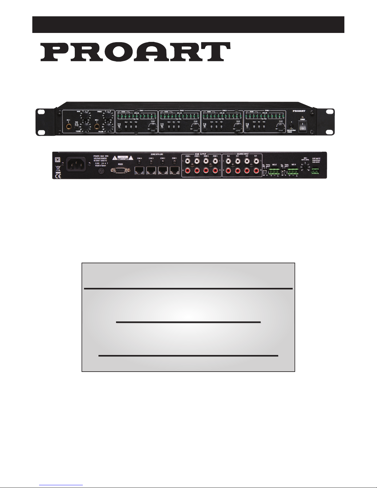
A 5430
20 19 18 17 16 15 14 13 14 13 12 11
21345
1. Power on / off.
Switch to “ON” position to turn power on and to “OFF” to turn
power off. The indicator will remain illuminated when the unit
is switched off via remote control.
2. IR (infra red) receiver windows.
This is for remote control operation. The remote wall plates
also have IR receivers and remote control operation is
identical for the main unit or wall plates.
3. Volume control for channel left and right output.
This volume knob is used to adjust the system output level.
When the volume control is adjusted, each LED indicator has
10 steps / increments, providing a total of 100 increments (ie
0 - 100%) Note there is no balance control in this unit.
Pushing the volume knob provides a channel mute function.
This switch is a toggle function. Pushing once mutes the
channel and pushing again returns the signal to its
former level.
4A.4B. Tone controls (bass and treble).
The centre LED indicator represents 0dB. Each LED indicator
is either a boost or defeat as follows:
1 LED =2dbB
2 LED’s =4dB
3 LED’s =6dB
4 LED’s =9dB
5 LED’s =12dB
Pressing either the up or down bass or treble selector button
once displays the current setting. Press either up or down to
adjust to the desired setting.
4C. Source input selector.
This selects the input channel that is to be directed to the
output channel being adjusted. Pressing either the up or
down source input selector button once displays the current
input source. Press either up or down to select the desired
source.
Overview
Congratulations on purchasing a Proart matrix mixer. This unit is designed for use in commercial installations such as pubs, clubs,
schools, function centres and the like. It is also suitable for large domestic installations.
The unit allows any combination of 4 auxiliary and 2 microphone / line inputs to be routed to any of 4 output zones.
• Any combination of 4 auxiliary and 2 microphone / line
inputs can be routed to any of 4 output zones.
• Separate bass and treble controls for all inputs
• Front mounted mic inputs and volume controls. Plus rear
mic / line inputs(switch selectable).
• Phantom power available for rear mic inputs
• Switch selectable on / off microphone muting
• Adjustable mic muting level.
• Separate rear mounted switch contact for mute control
• Separate microphone on / off switches for each zone
• LED level meters for volume setting
• LED level meter indication for bass and treble setting
• LED indication for source selection.
• Complete functionality via RS232 control
• 2 way RS232 communication
• Infra red remote control (supplied with main unit)
• Remote source volume controls (optional A 5432)
• Industry standard Cat 5e wiring for remote source volume
controls.
7
10
8
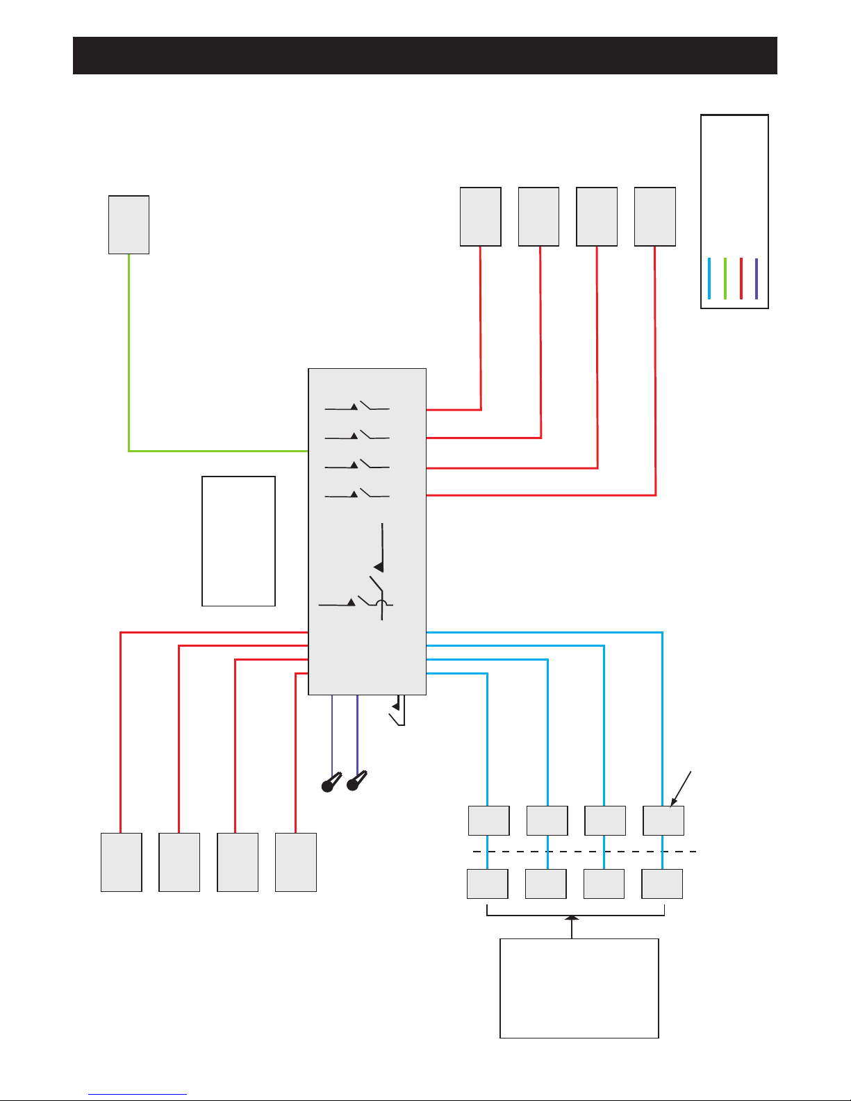
Installation
See Fig. 4 for typical installation and set up.
78
9
Features
Controls & Operation
Proart Audio Matrix Mixer
Page 6
Matrix allows any
input to any output
or combination of
outputs.
A 5430
4
3
2
1
MIC 1
MIC 2
1
2
3
4
Auxiliary level
stereo source
inputs
Microphone
inputs
4
3
2
1
Third party
control
External mute
(mutes inputs 1-4)
Additional A 5432
plates can be
used in the same
zone. These are
“daisy chained”.
Max 2 plates per
zone. Please
ensure plates on
the same zone
are programmed
identically.
Stereo
outputs
PA switches
(inhibits PA to that zone)
4 in / 4 out matrix
Matrix
RS232
Local source
input mutes
inputs 1-4
A 5342 Optional
remote source/volume
selection plate.
Cat 5e cable (max 300m)
Serial data cable
2 core shielded cable
2 x Shielded audio cable
Fig4. : Typical system configuration

Proart Audio Matrix Mixer
PagePage 5
Proart Audio Matrix Mixer
Command ASCII Hexadecimal
Power On $hPW1 24 68 50 57 31
Power Off $hPW2 24 68 50 57 32
CH1 MUTE On $aM01 24 61 4D 30 31
CH1 MUTE Off $aM02 24 61 4D 30 32
CH2 MUTE On $bM01 24 62 4D 30 31
CH2 MUTE Off $bM02 24 62 4D 30 32
CH3 MUTE On $cM01 24 63 4D 30 31
CH3 MUTE Off $cM02 24 63 4D 30 32
CH4 MUTE On $dM01 24 64 4D 30 31
CH4 MUTE Off $dM02 24 64 4D 30 32
CH1 VOL $aV79 24 61 56 37 39
CH1 VOL $aV01 24 61 56 30 31
CH2 VOL $bV?? 24 62 56 3? 3?
CH3 VOL $cV?? 24 63 56 3? 3?
CH4 VOL $dV?? 24 64 56 3? 3?
CH1 FUN_1 $aS01 24 61 53 30 31
CH1 FUN_2 $aS02 24 61 53 30 32
CH1 FUN_3 $aS03 24 61 53 30 33
CH1 FUN_4 $aS04 24 61 53 30 34
CH1 FUN_5 $aS05 24 61 53 30 35
CH1 FUN_6 $aS06 24 61 53 30 36
CH1 FUN_7 $aS07 24 61 53 30 37
CH1 FUN_8 $aS08 24 61 53 30 38
CH2 FUN_1 $bS01 24 62 53 30 31
CH2 FUN_2 $bS02 24 62 53 30 32
CH2 FUN_3 $bS03 24 62 53 30 33
CH2 FUN_4 $bS04 24 62 53 30 34
CH2 FUN_5 $bS05 24 62 53 30 35
CH2 FUN_6 $bS06 24 62 53 30 36
CH2 FUN_7 $bS07 24 62 53 30 37
CH2 FUN_8 $bS08 24 62 53 30 38
CH3 FUN_1 $cS01 24 63 53 30 31
CH3 FUN_2 $cS02 24 63 53 30 32
CH3 FUN_3 $cS03 24 63 53 30 33
CH3 FUN_4 $cS04 24 63 53 30 34
CH3 FUN_5 $cS05 24 63 53 30 35
CH3 FUN_6 $cS06 24 63 53 30 36
CH3 FUN_7 $cS07 24 63 53 30 37
CH3 FUN_8 $cS08 24 63 53 30 38
CH4 FUN_1 $dS01 24 64 53 30 31
CH4 FUN_2 $dS02 24 64 53 30 32
CH4 FUN_3 $dS03 24 64 53 30 33
CH4 FUN_4 $dS04 24 64 53 30 34
CH4 FUN_5 $dS05 24 64 53 30 35
CH4 FUN_6 $dS06 24 64 53 30 36
CH4 FUN_7 $dS07 24 64 53 30 37
CH4 FUN_8 $dS08 24 64 53 30 38
CH1 TRE $aT C 24 61 54 20 43 LED6 LED7 LED8 LED9 LED10 LED11 ON
CH1 TRE $aT B 24 61 54 20 42 LED6 LED7 LED8 LED9 LED10 ON
CH1 TRE $aT A 24 61 54 20 41 LED6 LED7 LED8 LED9 LED10 ON
CH1 TRE $aT 9 24 61 54 20 39 LED6 LED7 LED8 LED9 ON
CH1 TRE $aT 8 24 61 54 20 38 LED6 LED7 LED8 LED9 ON
CH1 TRE $aT 7 24 61 54 20 37 LED6 LED7 LED8 ON
CH1 TRE $aT 6 24 61 54 20 36 LED6 LED7 LED8 ON
CH1 TRE $aT 5 24 61 54 20 35 LED6 LED7 LED8 ON
CH1 TRE $aT 4 24 61 54 20 34 LED6 LED7 ON
CH1 TRE $aT 3 24 61 54 20 33 LED6 LED7 ON
CH1 TRE $aT 2 24 61 54 20 32 LED6 LED7 ON
CH1 TRE $aT 1 24 61 54 20 31 LED6 ON
CH1 TRE $aT 0 24 61 54 20 30 LED6 ON
CH1 TRE $aT-1 24 61 54 2D 31 LED6 ON
CH1 TRE $aT-2 24 61 54 2D 32 LED5 LED6 ON
CH1 TRE $aT-3 24 61 54 2D 33 LED5 LED6 ON
CH1 TRE $aT-4 24 61 54 2D 34 LED5 LED6 ON
CH1 TRE $aT-5 24 61 54 2D 35 LED4 LED5 LED6 ON
CH1 TRE $aT-6 24 61 54 2D 36 LED4 LED5 LED6 ON
CH1 TRE $aT-7 24 61 54 2D 37 LED4 LED5 LED6 ON
CH1 TRE $aT-8 24 61 54 2D 38 LED3 LED4 LED5 LED6 ON
CH1 TRE $aT-9 24 61 54 2D 39 LED3 LED4 LED5 LED6 ON
CH1 TRE $aT-A 24 61 54 2D 41 LED2 LED3 LED4 LED5 LED6 ON
CH1 TRE $aT-B 24 61 54 2D 42 LED2 LED3 LED4 LED5 LED6 ON
CH1 TRE $aT-C 24 61 54 2D 43 LED1 LED2 LED3 LED4 LED5 LED6 ON
CH2 TRE $bT 0 24 62 54 20 30 LED6 ON
CH3 TRE $cT 0 24 63 54 20 30 LED6 ON
CH4 TRE $dT 0 24 64 54 20 30 LED6 ON
Command ASCII Hexadecimal
CH1 BAS $aU C 24 61 55 20 43 LED6 LED7 LED8 LED9 LED10 LED11 ON
CH1 BAS $aU B 24 61 55 20 42 LED6 LED7 LED8 LED9 LED10 ON
CH1 BAS $aU A 24 61 55 20 41 LED6 LED7 LED8 LED9 LED10 ON
CH1 BAS $aU 9 24 61 55 20 39 LED6 LED7 LED8 LED9 ON
CH1 BAS $aU 8 24 61 55 20 36 LED6 LED7 LED8 LED9 ON
CH1 BAS $aU 7 24 61 55 20 37 LED6 LED7 LED8 ON
CH1 BAS $aU 6 24 61 55 20 38 LED6 LED7 LED8 ON
CH1 BAS $aU 5 24 61 55 20 39 LED6 LED7 LED8 ON
CH1 BAS $aU 4 24 61 55 20 41 LED6 LED7 ON
CH1 BAS $aU 3 24 61 55 20 42 LED6 LED7 ON
CH1 BAS $aU 2 24 61 55 20 43 LED6 LED7 ON
CH1 BAS $aU 1 24 61 55 20 43 LED6 ON
CH1 BAS $aU 0 24 61 55 20 43 LED6 ON
CH1 BAS $aU-1 24 61 55 2D 43 LED6 ON
CH1 BAS $aU-2 24 61 55 2D 43 LED5 LED6 ON
CH1 BAS $aU-3 24 61 55 2D 43 LED5 LED6 ON
CH1 BAS $aU-4 24 61 55 2D 43 LED5 LED6 ON
CH1 BAS $aU-5 24 61 55 2D 43 LED4 LED5 LED6 ON
CH1 BAS $aU-6 24 61 55 2D 43 LED4 LED5 LED6 ON
CH1 BAS $aU-7 24 61 55 2D 43 LED4 LED5 LED6 ON
CH1 BAS $aU-8 24 61 55 2D 43 LED3 LED4 LED5 LED6 ON
CH1 BAS $aU-9 24 61 55 2D 43 LED3 LED4 LED5 LED6 ON
CH1 BAS $aU-A 24 61 55 2D 43 LED2 LED3 LED4 LED5 LED6 ON
CH1 BAS $aU-B 24 61 55 2D 43 LED2 LED3 LED4 LED5 LED6 ON
CH1 BAS $aU-C 24 61 55 2D 43 LED1 LED2 LED3 LED4 LED5 LED6 ON
CH2 BAS $bU 0 24 62 55 20 30 LED6 ON
...
CH3 BAS $cU 0 24 63 55 20 30 LED6 ON
...
CH4 BAS $dU 0 24 64 55 20 30 LED6 ON
...
...
ALL CH. PAGE ON $hPA1 24 68 50 41 31
ALL CH. PAGE OFF $hPA2 24 68 50 41 32
CH1 PAGE ON $aPA1 24 61 50 41 31
CH2 PAGE ON $bPA1 24 62 50 41 31
CH3 PAGE ON $cPA1 24 63 50 41 31
CH4 PAGE ON $dPA1 24 64 50 41 31
CH1 PAGE OFF $aPA2 24 61 50 41 32
CH2 PAGE OFF $bPA2 24 62 50 41 32
CH3 PAGE OFF $cPA2 24 63 50 41 32
CH4 PAGE OFF $dPA2 24 64 50 41 32
Request
Power Status $aR 1 24 61 52 20 31
ACK
Power On $hPW1 24 68 50 57 31
Power Off $hPW2 24 68 50 57 32
CH1 Mute Status $aR 2 24 61 52 20 32
ACK
CH1 MUTE On $aM01 24 61 4D 30 31
CH1 MUTE Off $aM02 24 61 4D 30 32
CH1 TREBLE Status $aR 3 24 61 52 20 33
ACK
CH1 TREBLE $aT 0 24 61 54 20 30
CH1 BASS Status $aR 4 24 61 52 20 34
ACK
CH1 BASS $aU 0 24 61 55 20 31
CH1 SOURCE Status $aR 5 24 61 52 20 35
ACK
CH1 SOURCE $aS04 24 61 53 30 34
CH1 VOL Status $aR 6 24 61 52 20 36
ACK
CH1 VOL $aV?? 24 61 56 3? 3?
RS-232 Command List:

Proart Audio Matrix Mixer
Page 2
5.Microphone ON/OFF switch.
This switch enables or disables the microphone signal to
pass through that zone.
6. LED display for/volume/bass/treble/function.
This displays current volume level. When any of the input
source, bass or treble buttons are pressed the LED’s display
the current setting for the function selected.
7.Level controls for microphone inputs.
This controls the microphone level for either the front panel
jack or the rear panel screw connector inputs.
8.Microphone input jacks.
We only recommend balanced (tip ring sleeve) microphones
for use with this item. The front panel inputs will only accept
dynamic microphones.
9. Microphone bass and treble controls.
These control both the front and rear microphones.
10. Mute function.
Sets muting of input sources to ON or OFF.--
11. External mute input.
This is a 0 volts switch contact. Short the terminals together
to mute the music sources. This is for a push to talk
microphone. For this to function, the microphone button on
the desired “muting” channel(s) must be set to ON.
12. Mute volume
This switch sets the vox muting sensitivity for microphone
input 1.
13. 13 Rear microphone input jack Mic-1, and Mic-2.
This is a terminal for balanced microphones. To connect
unbalanced microphones use a wire link and connect
“negative“ and ground terminals together.
When using phantom powered microphones set the phantom
DIP switch on (down position).
14. Mic / line switch.
This allows a line level input to be connected to the rear
input terminals.
15. Input sources left and right inputs 1, 2, 3 and 4.
16. Outputs left and right 1, 2 3, and 4.
17. Cat 5e sockets for remote wall plate wiring.
18. RS232 control.
See page 5 for RS232 control details and list of commands.
19. 240V ac fuse.
If the fuse blows, please disconnect the power cord and
replace fuse using the same value 1.0Aamp M205 (20 x
5mm) size SLOW BLOW type. If the fuse blows again contact
your dealer for further servicing.
20. AC input. IEC 3 pin type connector
Remote control functions:
21. Power ON/OFF
22. Source selection 1-4.
23. Volume / Treble / Bass adjustment Zone 1.
24. Volume / Treble / Bass adjustment Zone 2.
25. Volume / Treble / Bass adjustment Zone 3.
26. Volume / Treble / Bass adjustment Zone 4.
Optional A 5432 Zone Wallplates
This keypad is programmed at the factory with a range of
user selectable source descriptions. Each keypad has been
preset at the factory with the default zone number of 01 and
all 4 source names have been assigned the name AUX.
22
21
23
24
25
26

Proart Audio Matrix Mixer
PagePage 3
Proart Audio Matrix Mixer
Keypad Installation
& Set Up
The zone number MUST be set
BEFORE the keypad is installed in
the wall and BEFORE any changes
are made to the source name. This
will prevent accidentally erasing
programming on one keypad while
changing the zone number on
another keypad (see Fig. 3).
An optional stereo audio source
wall plate (eg 2 x RCA or 3.5mm
plate) can be connected to the
wall plate.
Connect the Cat 5e cable using standard T568A wiring format
(see page 4 fig. 1).
Switch on the power for the A 5430 control unit and press the
mute / power button on the keypad to turn it on. The unit will
display PWR-ON.
Press the zone ID button on the end of the wall plate (see
page 4 fig. 2) and the zone number will be displayed on the
LCD screen. Press and release the zone button again to
increment the zone number one by one until the required
zone number is displayed. Each zone requires a unique ID.
Once the zone numbers have been assigned the keypad can
be installed.
1. To enter the source name set up screen, press and hold
the source up button for approx 7sec. The text name
NAME-Y will appear for a moment and the IR indicator will
begin flashing.
2. The source number will now be displayed to the right of
the volume level numbers on the LCD and corresponds to
the source input number on the back of the controller.
Note that the source number will be displayed for about 10
seconds and will then disappear, but you can continue to
assign a source name to that source number until you are
ready to assign the next source.
3. Press volume up or volume down buttons to identify the
source number to be programmed.
4. Once source number 1 is displayed, use the source up and
source down buttons to scroll through the list of source
names until you select the source you require for that
input. See table 1.
5. Repeat steps 3 and 4 for each of the 4 sources. Remember
to select NA for any source input in which no component
source is connected or if you want to skip that source in
that zone.
6. Once all sources have been assigned a source name press
Enter to exit set up. Please note that after 10 - 15 seconds
of inactivity the keypad will also automatically exit set up,
saving your last setting.
The text NAME-N will appear for a moment and the IR
indicator will stop flashing once you exit set up.
(Note that if the IR indicator light remains lit after exiting set
up, power off the keypad and then power back on.)
Using the keypad
The keypad will enter sleep mode after approximately 20
seconds of inactivity. To “wake up” the keypad simply press
any button.
Keypad functions:
27. Source up/down: These buttons are used to scroll
through the sources available to the zone that you are in.
28. Volume up/down: These buttons increase and decrease
the volume with range from 00 - 99. The volume level is also
displayed as a 10 position bar graph.
29. Enter: Used when assigning source names during setup.
30. Mute: Once powered on press the button to mute the
speakers in that zone. When muted the LCD will indicate
“MUTE”. Press the mute button again to restore the music to
previous level.
31. 3.5mm Stereo socket: Allows connection of external
music source. This will take priority over rear RCA connected
input source.
Specifications:
OUTPUT: ..................................................>6V at 10K Ohms.
FREQUENCY RESPONSE: ..........+0/-0.5 dB 10 Hz to 50 KHz
THD DISTORTION: ....................< 0.001% at (20 to 20 KHz)
HUM & NOISE: .................................................... < -110 dB
CROSSTALK: ..............................................> 50 dB At 1KHz
INPUT IMPEDANCE : ..........................20K Ohms (balanced)
47K Ohms (unbalanced)
VOLTAGE GAIN : ..............................Line 10 dB. Mic 50 dB.
POWER REQUIREMENTS: ..........20VA 90-240V ac 50/60 Hz
FINISH: ......................................................................Black
A 5432
27
29
28
30
31
RJ45 RJ45
Rotary
Switch
Wall plate rear detail.

Proart Audio Matrix Mixer
Page 4
CONNECTORS:
Front panel......................................6.35mm TRS sockets
Rear panel
Mute ............................2 way pluggable screw terminals
Mic 1, 2 ........................3 way pluggable screw terminals
Source inputs..............................stereo L/R RCA sockets
Zone outputs ..............................stereo L/R RCA sockets
Remote wall plates ..........................RJ45 cat 5e sockets
RS232............................................................DE9 female
DIMENSIONS: ........................420(W) x 44(H) x 200(D) mm
RS-232 Control Information:
Protocol:....................................................................RS-232
Baud rate:..............................................................9600 bps
Data Bit: ......................................................................8 bits
STOP Bit: ......................................................................1 bit
Parity: ..........................................................................None
Flow Cntrl:........................................................................No
Fig2. : Location of zone ID button.
Stereo Input Panel
L
R
Fig3. : If you connect a stereo input panel to this keypad,
first remove the jumper inside the 3 way PCB connector
and connect the stereo input panel with A 5038 connection lead.
WIRING DIAGRAM
8P8C PLUG
1
2
3
6
4
5
7
8
1 - White / Green
2 - Green
3 - White / Orange
6 - Orange
4 - Blue
5 - White / Blue
7 - White / Brown
8 - Brown
8P8C PLUG
Fig1. : T 568A standard Cat 5e RJ45 wiring configuration.
Table 1. : Source names
TV Television
TV-2 Television
PHONE Typically used for mobile phones with
audio playback capability
MP3 MP3 player
POD iPod
®
, iPod®dock or similar
POD-2 iPod
®
, iPod®dock or similar
SERVR Media server
COMP Computer
CABLE Cable box
SATRD Satellite radio
SATTV Satelite TV
DVD DVD player
CD Compact disc player
CD-2 Compact disc player
RADIO Radio
TUNER Radio AM, FM or HD tuner
NA Not Available - Used to denote a source
input that has no component connected
to it or to identify a source component
that is not available in that zone.
BABY Baby monitor
AUX Auxiliary
AUX-2 Auxiliary
 Loading...