

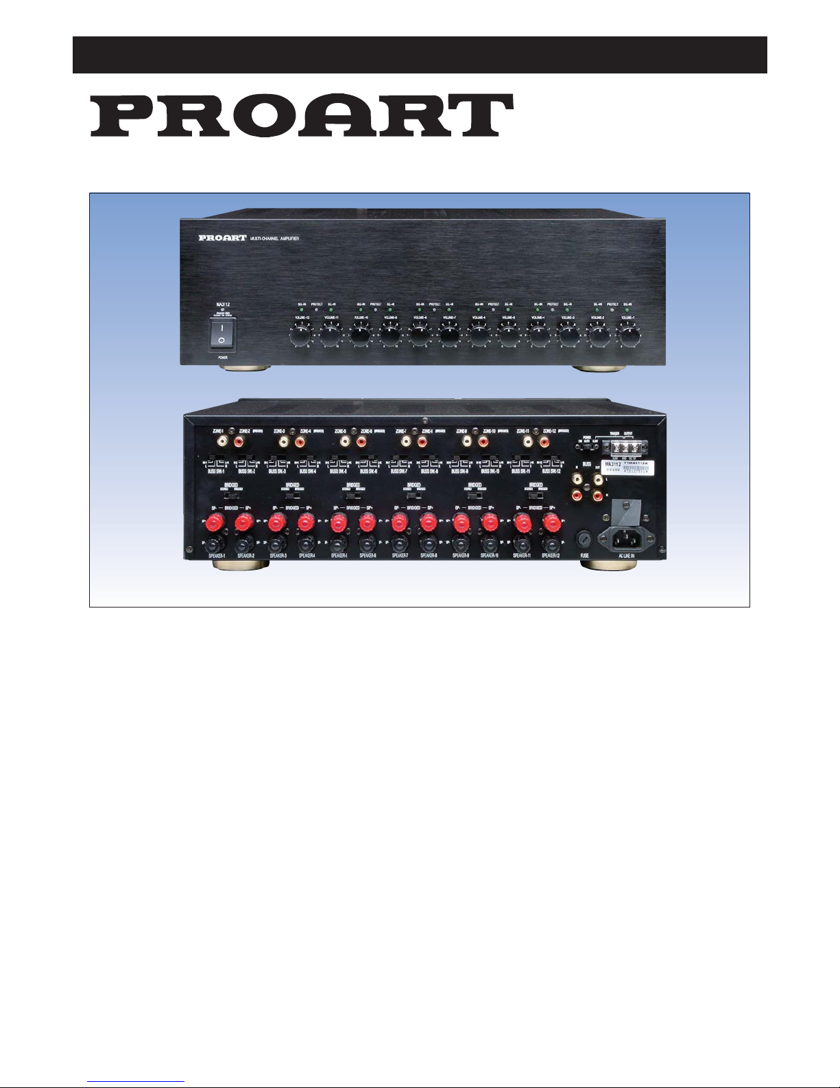
A 5024 Multi-Zone Amplifier
Operating Instructions
Overview
Congratulations on purchasing the A 5024 multichannel
amplifier. It is suitable as a stand alone system for multi
room (multi zone) installations, or for connection to an
A 5020 matrix controller for more advanced audio
switching (contact your dealer for more information on
the A 5020).
The A 5024 provides up to 6 stereo speaker zones or 12
mono speaker zones or a combination of both.
Each zone can be configured to accept either a dedicated,
or common input source.
Any combination can be used allowing for instance
background music to be playing in dining room & entertaining areas while home theatre effects are playing in
the lounge.
The BUSS input is best used when it is connected to an
audio switching device such as a home theatre receiver.
This allows you to quickly switch audio sources across
multiple zones at once.
Features
• 6 stereo speaker zones or 12 mono speaker zones or a
combination of both. Each rated at 40W into 8Ω
speakers.
• Each pair of amplifiers are bridgeable delivering
120W into 8Ω.
• Each amplifier has a choice between shared BUSS or
individual zone inputs.
• Common BUSS output allows infinite number of
amplifiers to be used.
• The unit can be powered up via signal detection or
external trigger (5-24V DC).
• Signal LED for each channel
• Amplifier “protect” LED per amplifier pair
• 12 individual volume controls
• Input signal limiter.
Installation
The amplifier can be configured in a number of different
configurations. Please consult the configuration diagrams on pages 2, 3 & 4 as a guide for setting up your
system.
Page 1

Proart Multizone Audio Distribution System
Page 2
SYSTEM OPERATION
This system can be configured to operate in 3 different modes. These are selected via the rear mounted
3 position power switch, marked ON, Auto, 5-24V.
The front mounted power rocker ON/OFF switch
must be ON for any of these modes to operate.
ON Mode:
All amplifiers are permanently ON regardless of
any signal applied.
Auto Mode:
The appropriate amplifiers automatically switch
ON, only when an input signal is present. This
saves power and uneccessary heat build up.
5-24V Mode:
Applying 5-24VDC to the trigger terminals switches
all amplifiers ON. This is useful for when the amplifier is located in a remote, difficult to access location
ie: ceiling.
OTHER FEATURES
Protection LEDs
Within 1 – 2 seconds after switch on the PROTECT
LEDs will turn green indicating normal operation.
If there is an amplifier over-load the PROTECT
LEDs will turn red indicating a fault.
Trigger Input / Output
The trigger terminals can be used to turn the amplifier on via a remote switch or external controller.
See figure 2 for examples of how this feature can be
used.
Amplifier Bridging
For speakers requiring extra power 2 channels may
be bridged to provide a single mono 120W RMS
channel.
When using this configuration ensure input source
is connected to the RCA labelled “bridged”.
Specifications
Power (at 8 Ohms THD < 1%): 40W RMS (80W Max.)
Power (at 4 Ohms THD < 1%): 60W RMS (120W Max.)
Bridged Power (At 8 Ohms): 120W RMS (200W Max.)
Distortion: ................................................ < 0.002%
S/N Ratio (IEC-A): .......................................... > 90db
Frequency Response (+/- 1db) : ............10Hz-40KHz
Dimensions: ..................483 x 132 x 380m(W x H x D)
Weight: ..................................................13.5 Kg (Net)
STEREO BRIDGED
BRIDGED
BUSS SW-1 BUSS SW-2
ZONE-1 ZONE-2
L+R
R
IN-1
L
L+R
R
IN-2
L
SP-
SP+
SP-
SP+
LEFT
RIGHT
CD Player
40W 40W
8Ω
8Ω
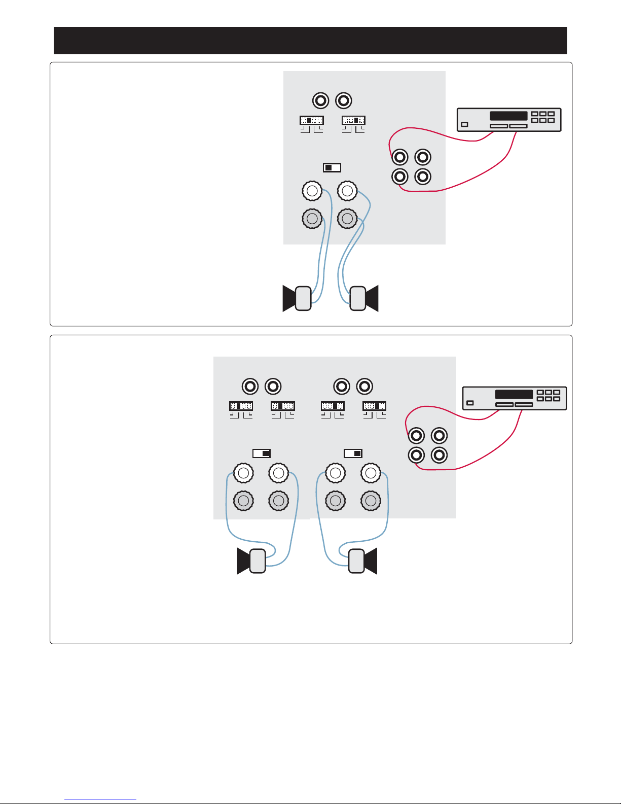
CONFIGURATION 1
Stereo output 40W
Dedicated source
1. Set “bridged” switch to
stereo
2. Set BUSS switch for
Zone 1 to IN
3. Set BUSS switch for
Zone 2 to IN
4. Connect input source to
zone 1 & 2 input RCA’s.
5. Connect speakers to
terminals.
In this configuration the
speaker pair has a dedicated input source. This source
cannot be shared across
other speaker zones.
STEREO BRIDGED
BRIDGED
BUSS SW-1
SP-
SP+
LEFT
L+R
R
IN-1
L
BUSS
IN OUT
Home Theatre Receiver
40W
8Ω
CONFIGURATION 2
Single mono speaker
Common BUSS input source
1. Set “bridged” switch to stereo
2. Set BUSS switch to L+R
3. Connect input source to BUSS IN RCA’s
4. Connect speaker to terminals.
In this configuration all speaker zones can share the BUSS source.
Note: speaker will receive a mixed L+R signal)
Proart Multizone Audio Distribution System
Page 3
BUSS SW-3 BUSS SW-4BUSS SW-1 BUSS SW-2
ZONE-1 ZONE-2
SP- SP+ SP- SP+
LEFT
RIGHT
L+R
R
IN-1
L
L+R
R
IN-2
L
L+R
R
IN-3
L
L+R
R
IN-4
L
ZONE-3 ZONE-4
STEREO BRIDGED
BRIDGED
STEREO BRIDGED
BRIDGED
BUSS
IN OUT
Home Theatre Receiver
Bridged 120W Bridged 120W
8Ω
8Ω
CONFIGURATION 4
High power stereo output 120W
Common BUSS input source
Bridged output
1. Set “bridged” switch to bridged
2. Set BUSS switch for Zone 1 to L
3. Set BUSS switch for Zone 2 to L
4. Set BUSS switch for Zone 3 to R
5. Set BUSS switch for Zone 4 to R
6. Connect stereo input source to
BUSS IN RCA’s
7. Connect left speaker negative
wire to SP- and left speaker
positive wire to SP+ (Zone 1 & 2
terminals).
8. Connect right speaker negative
wire to SP- and right speaker
positive wire to SP+ (Zone 3 & 4
terminals).
In this configuration all speaker
zones can share the BUSS source.
Bridging will provide 120W RMS per
speaker.
STEREO BRIDGED
BRIDGED
BUSS SW-1 BUSS SW-2
ZONE-1 ZONE-2
L+R
R
IN-1
L
L+R
R
IN-2
L
SP-
SP+
SP-
SP+
LEFT
RIGHT
BUSS
IN OUT
Home Theatre Receiver
40W 40W
8Ω
8Ω
CONFIGURATION 3
Stereo output 40W
Common BUSS input source
1. Set “bridged” switch to stereo
2. Set BUSS switch for Zone 1 to L
3. Set BUSS switch for Zone 2 to R
4. Connect input source to BUSS IN RCA’s
5. Connect speakers to terminals.
In this configuration all speaker zones can share
the BUSS source.

Proart Multizone Audio Distribution System
Page 4
CD Player
Home Theatre Receiver
BUSS SW-1
BRIDGED
L+R L+R IN-3 IN-4 LL R R
STEREO BRIDGED
BUSS SW-2 BUSS SW-5 BUSS SW-6BUSS SW-3 BUSS SW-4 BUSS SW-7 BUSS SW-8
STEREO
ZONE-1 ZONE-2 ZONE-3 ZONE-4 ZONE-5 ZONE-6 ZONE-7 ZONE-8
ZONE-9 ZONE-10 ZONE-11 ZONE-12
ZONE 1 / Bathroom
ZONE 2 / Hall
ZONE 3 / Bedroom
STEREO
L R
BUSS
IN OUT
TO SECOND
AMPLIFIER
ZONE 4 / Games Room
ZONE 5 / Outdoor Entertaining
STEREO
L R
ZONE 6 / Dining Room
BUSS SW-9 BUSS SW-10 BUSS SW-11 BUSS SW-11
BUSS Input
Individual Source Input
ON
AUTO
5-24V DC
Figure 1: Complete system configuration. Note that a home theatre receiver can be used as source switcher for the BUSS
input allowing music, DVD sound or other audio source to be played through zones using the BUSS input. Additionally the
A 5020 Matrix Control Unit (available separately) can be connected to individual source inputs or the shared BUSS input. This
provides up to 8 audio program sources which can be easily switched via remote control or wallplate.
5-24V DC In
GND
12V DC Out
Remote switch
ie: wallplate.
External device or controller
ie: any appliance with a DC
voltage output
5-24V DC In
GND
12V DC Out
Figure 2: A 5-24V input & ground is provided for an external controller.
The 12V output can be connected to a remote switch.
Distributed by Altronic Distributors Pty. Ltd.
Perth. Western Australia.
Phone: 1300 780 999 Fax: 1300 790 999
Internet: www.altronics.com.au
 Loading...