

Proaqua PRO-S-80E User Manual
Professional Water Filtration Systems
www.proaquawater.com.com
WATER SOFTENER
OWNER’S MANUAL

TABLE OF CONTENT
SECTION PAGE
INSPECTION & PREPARATION ....................................... 2 4
INSTALLATION DIAGRAM .................................................... 5
VALVE SETUP ................................................................. 6 7
SYSTEM INSTALLATION .................................................... 8 10
VALVE PROGRAMING .................................................... 11 15
ADVANCE SETTINGS ................................................................. 17 21
TOTAL GALLONS CALCULATION WORKSHEET ............ 22
FEATURE & DISPLAYS .................................................... 23
Restore Factory Settings ........................................... 24
Manual Queued Regeneration ............................ 24
Manual Immediate Regeneration ............................ 25
Stop Regenerating .......................................................... 25
PRODUCT DIMENSION .................................................... 26
SYSTEM TROUBLESHOOT .................................................... 27
NOTES ............................................................................... 28
LIMITED PRODUCT WARRANTY ....................................... 29
- 1 -

INSPECTION & PREPARATION
IMPORTANT!
!
System Inspection
Please take the system and all the components out of the box. Inspect the system and all the connection fittings
carefully, make sure nothing is damaged during shipping. If any part is cracked or broken, please do not proceed
with the installation and contact Pro+Aqua or your distributor for an exchange or diagnosis.
Before installing - Please read the entire manual and become familiar with instructions and parts needed
before proceeding with the installation.
System Components Breakdown (See Dia. A)
• Aquatrol Valve Electronic Meter
• 5’ of 3/8” Brine Line
• Brine Tank
• Bypass Valve
• Drain Line Fitting
• 14’ of 1/2” Drain Line
• Top Distributor
• Resin Media
• Resin Tank
• Riser Tube & Bottom Distributor
• Control Valve
• Upper Distributor Basket
• Power Transformer
Required Tool List for System Installation
• Channel Locks
• Screwdriver
• Teflon Tape
• Razor Knife
• Two Adjustable Wrenches
• Plastic inlet and outlet fittings are included with
the softener. To maintain full valve flow, 1” pipe to
and from the softener fittings are recommended.
• Use copper, brass, or PEX pipe and fittings.
Some codes may also allow PVC plastic pipe.
• Additional tools may be required if modification
to home plumbing is required.
Required Components not Included with the System
Extra Course Grade or Crystal water softener salt is needed to fill the brine tank
- 2 -

INSPECTION & PREPARATION CONT.
II. System Operation Parameter and Installation checklist
IMPORTANT!
!
1. Water Temperature Parameters
2. Water Pressure Parameters
The following condition for feed water supply must be met or warranty will be void and manufacturer
assumes no responsibility for damage to system or property.
System must not be installed at an area where it is exposed to direct sunlight and must be protected against
freezing and extreme heat.
• Maximum: 100º F (37.8º C)
• Minimum: 32º F (0º C)
The maximum allowable inlet water pressure is 125 psi. If daytime pressure is over 80 psi, night time
pressure may exceed the maximum allowed water pressure. Use a pressure reducing valve (PRV) to reduce
the pressure if needed.
• Maximum: 125 PSI (8.78 kg/cm2)
• Minimum: 25 PSI (1.75 kg/cm2)
3. Chlorine, Chloramine, & Iron Tolerance
Softener resin may degrade in the presence of chlorine or chloramines. If the feed water contains chlorine,
chloramines, or iron, reduced life of the resin could occur. In these conditions, a whole house carbon or iron
filtration system with chlorine, chloramine or iron reducing media is recommended.
• Maximum: 2 ppm
4. Pre-installation & environment checklist
• Do not use with water that is microbiologically unsafe or of unknown quality without adequate disinfection
before or after the system.
• Properly ground to conform with all governing code and ordinances. Use only lead-free solder and flux for
all sweat-solder connections as required by state and federal codes.
• Place the softener as close as possible to the pressure tank (well system) or water meter (city water).
• Place the softener as close as possible to a floor drain, or other acceptable drain point (laundry tub, sump,
standpipe, etc.).
• Connect the softener to the main water supply pipe before the water heater. Do not run hot water through
the softener. Temperature of water passing through the softener must be less than 100º F.
• It is recommended to not supply softened water to outside faucets and irrigation system as soft water
exposure can be detrimental to plant life. Be sure to bypass the softener when watering grass or plants. It
is recommended to install a “Y” pipe for outside use and home use.
• Place softener in a place where water damage is least likely to occur if a leak develops.
• An electric outlet with 120 volt is needed within 6 feet of the softener. The transformer has an attached 8
foot power cable. Be sure the electric outlet and transformer are protect from moisture and water.
• If installing in an outside location, necessary steps must be taken to assure the softener, installation
plumbing, wiring, etc., are protected from the elements and contamination sources.
• The resin tank should be located close to a drain to prevent air breaks and back flow.
• The brine tank should be located no more than 15’ from the resin tank.
• Softener should be installed with a vacuum breaker to avoid damage to tank.
- 3 -
INSPECTION & PREPARATION CONT.
III. Installation Safety Guide
• Handle with care when moving the water softening system. Do not turn upside down, drop, drag, or set on
areas with sharp protrusions.
• The system works on standard 110v power plug only. Do not use any other transformer except the ones that is
included with the system
• Transformer must be plugged into an indoor 120 volt, grounded outlet only.
• Use clean water softening salt only with at least 99.5% pure. Extra course grade or crystal salt are
recommended. Do not use rock, block, granulated or ice cream making salts. They contain contaminants that
could cause problems during maintenance
• Always keep salt lid in place on the softener unless servicing or refilling the unit.
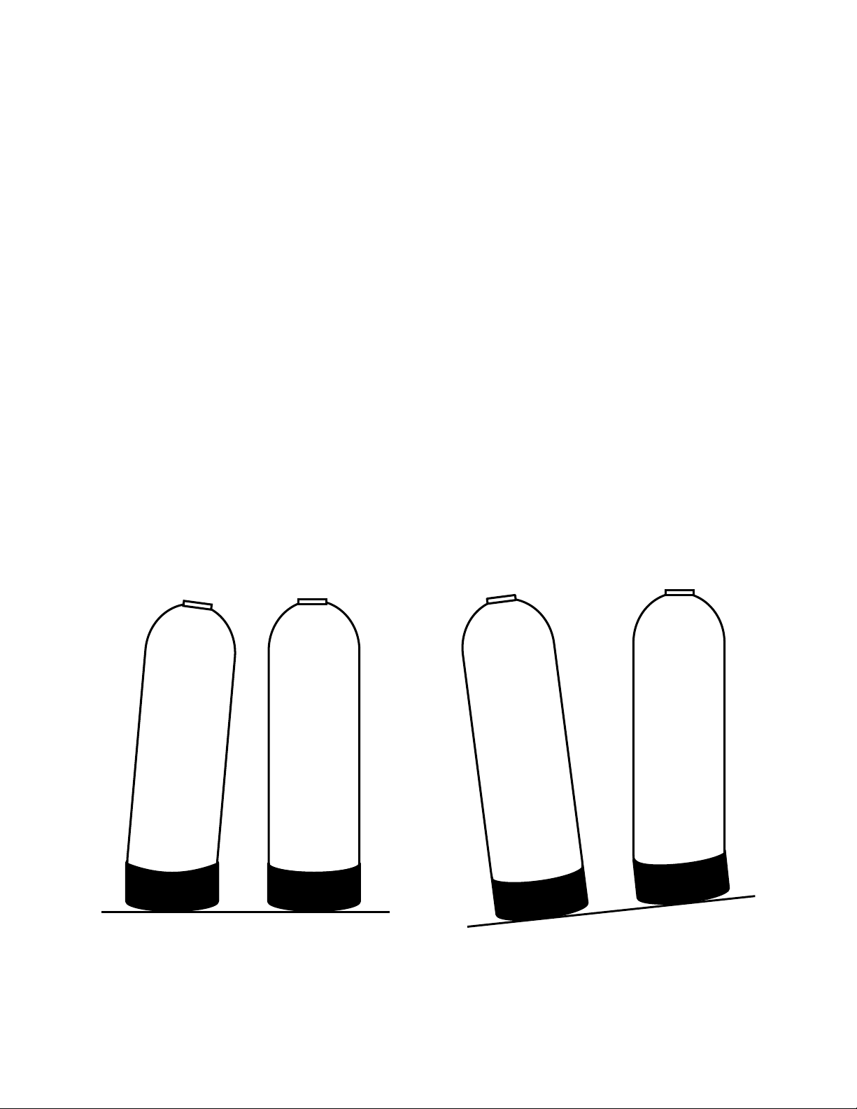
• All of our resin tanks have level adjusting tank bases. These tanks are designed to work with a “floating” base.
This allows the tank to be leveled on any surface. Some applications may not have level surface to place the
tank. The floating base allows the tank to be leveled within the base and ensure proper operation. Sometimes
the based can shift during shipping. It can be adjusted back by lifting the tank up no higher than 5” - 10”, and
letting it drop to help level the base.
CORRECT CORRECTINCORRECT INCORRECT
- 4 -
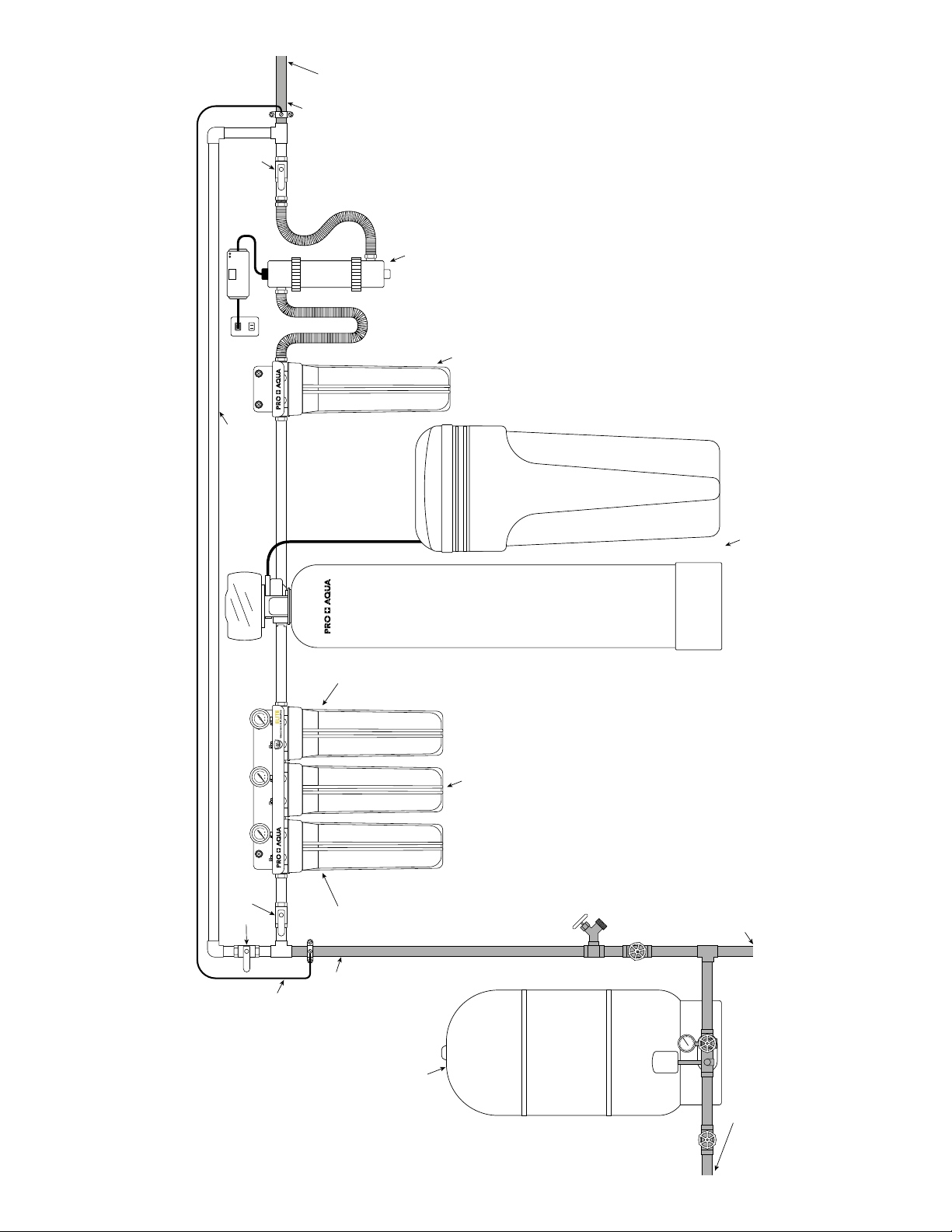
Optional Water Bypass
To Home
Brass Pipe
Galvanized /
Ball Valve
Optional
UV Filter
Optional
Post Filter
Sub-Micron
INSTALLATION DIAGRAM
Water Softener
Stage 3
Housing
PRO-100-E System
Optional Whole House System
Stage 1
Ball Valves
Housing
City Water Source
Ground Jumper Wire
Galvanized / Brass Pipe
Well Water Pressure Tank
Well Water Source
- 5 -
VALVE SETUP
IMPORTANT!
!
Locate and test the main water supply valve to the home before installing the system. If the main water
supply valve fails to shut o the water completely during the test, we recommend contacting a licensed
plumber to fix the valve before begin installing the system.
WARNING!
If the system is installed on a metal (Conductive) plumbing system, i.e.. copper or galvanized metal, the
plastic components of the system will interrupt the continuity of the plumbing system. As a result, any
arrant electricity from improperly grounded appliances downstream or potential galvanic activity in the
plumbing system can no longer ground through contiguous metal plumbing. Some homes may have
been built in accordance with building codes, which actually encouraged the grounding of electrical
appliances through plumbing. A grounded “jumper wire” bridging the equipment and reestablishing the
contiguous conductive nature of the plumbing system must be installed prior to your system use.
WARNING!
Electric Hot Water Tanks: Turn o the power to the unit first to avoid damage.
Well Water: Power o the well water pump and then shut o the main water supply valve.
1
2
Shut O Main Water Supply
1. Locate the main water supply valve to the house and completely turn o by turning the handle
clockwise.
2. Test to see if the water is completely shut o by turning on the cold water on the closest faucet. If the
cold water cannot be shut o, please contact your local plumber to fix the valve before installing the
system.
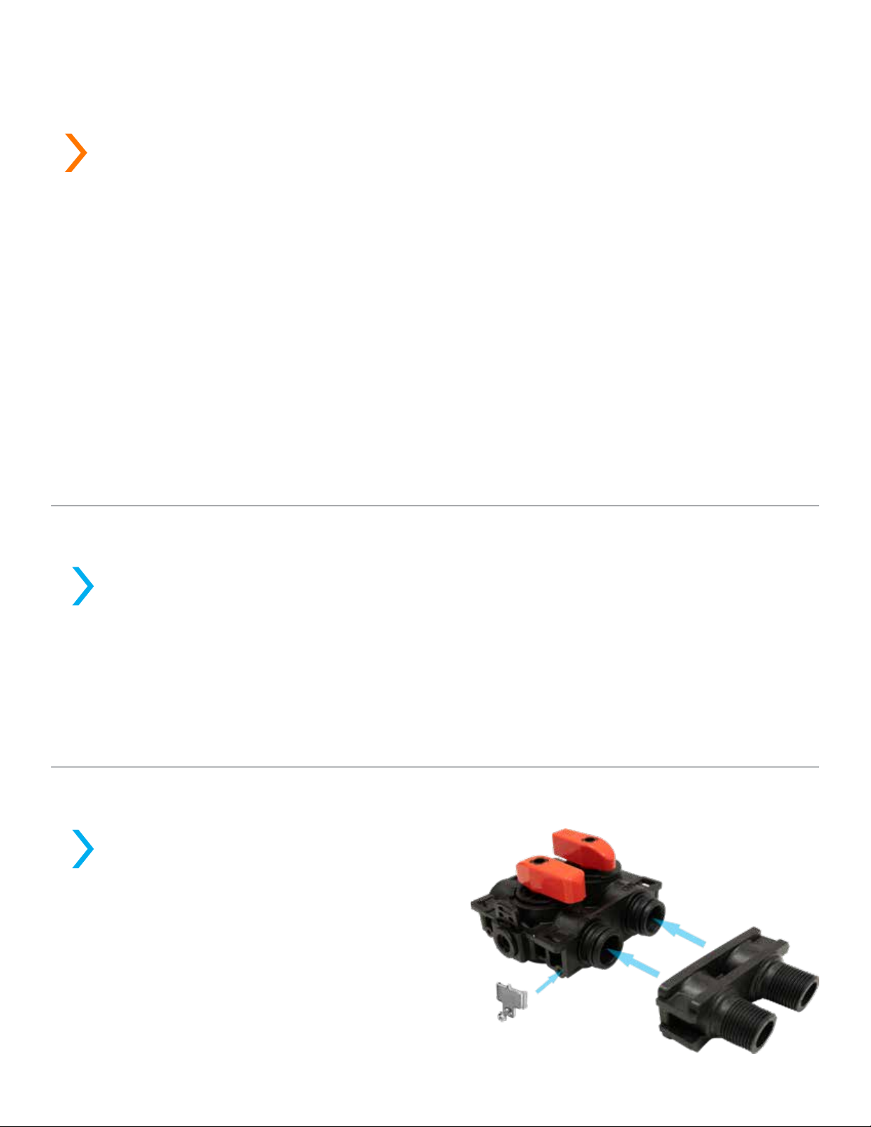
Bypass Valve Assembly & Installation
1. Lubricate the o-rings on the Bypass Valve
then attached the Yoke to the Bypass valve
by pressing the yoke onto the Bypass (both
sides of the ports at the same time).
2. Ensure to lubricate the o-rings to avoid any
leaks.
3. Attach the metal clips to both sides of the
Bypass Valve to hold the Yoke to the Bypass.
(Skip this step if the Yoke is already preinstalled. )
- 6 -
VALVE SETUP CONT.
4. Attached the other end of the bypass valve onto the control head and secure it with the metal plate.
Make sure the o-rings are lubricated before installing.
3
Softener Preparation
1. Remove the resin tank from carton
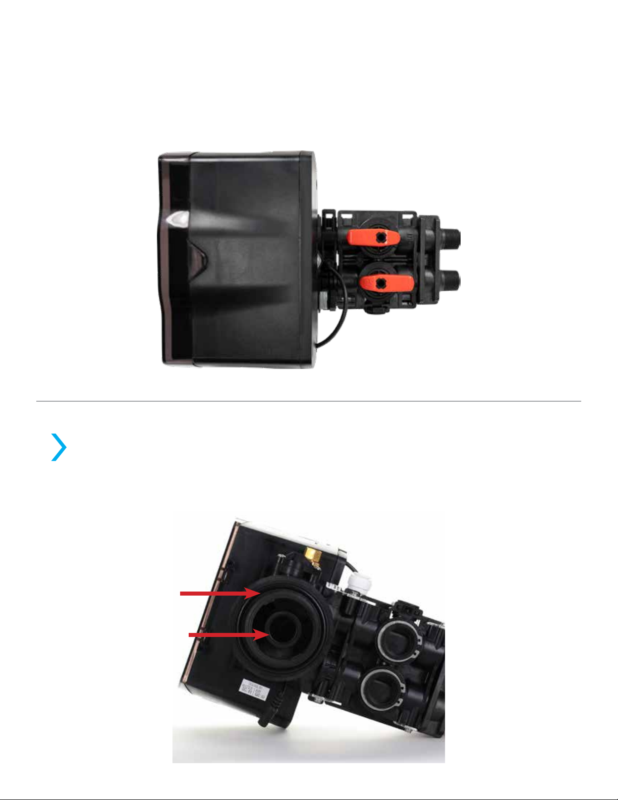
2. Lubricate both O-rings on the bottom of the control valve (center and outer).
- 7 -
SYSTEM INSTALLATION
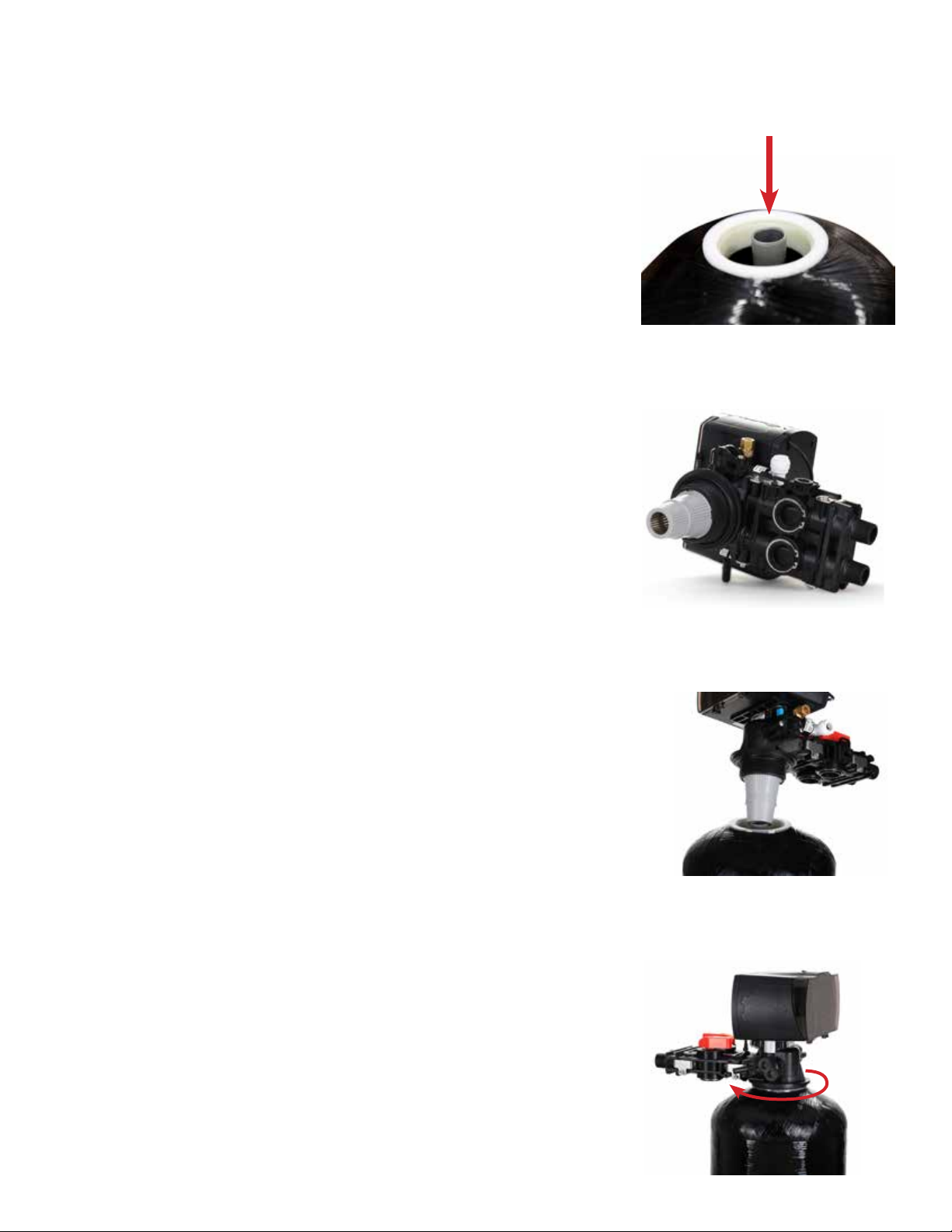
3. Lubricate the riser tube located on the opening of the tank.
4. Install the upper basket on the bottom of the valve by lining up the
tabs, pressing in, then turning the basket counterclockwise to lock it in
place.
5. Place the upper basket over the distributor tube and push the valve
on the tank. Thread the valve on the tank by turning it clockwise.
Be sure not to cross-thread the valve on the tank. The valve should
thread easily in the tank. If not, it may be cross-threaded.
6. Tighten the valve hand tight, then snug it further by tapping it with
the palm of the hand. DO NOT use tools to tighten the valve or
damage could occur.
- 8 -
SYSTEM INSTALLATION CONT.
!
IMPORTANT!
On copper plumbing systems be sure to install a grounding wire between the inlet and outlet piping to
maintain grounding.
WARNING!
Any solder joints being soldered near the valve must be done before connecting any piping to the valve.
Always leave at least 6” (152 mm) between the control valve and joints being soldered when soldering
pipes that are connected to the valve. Failure to do this could cause damage to the valve.
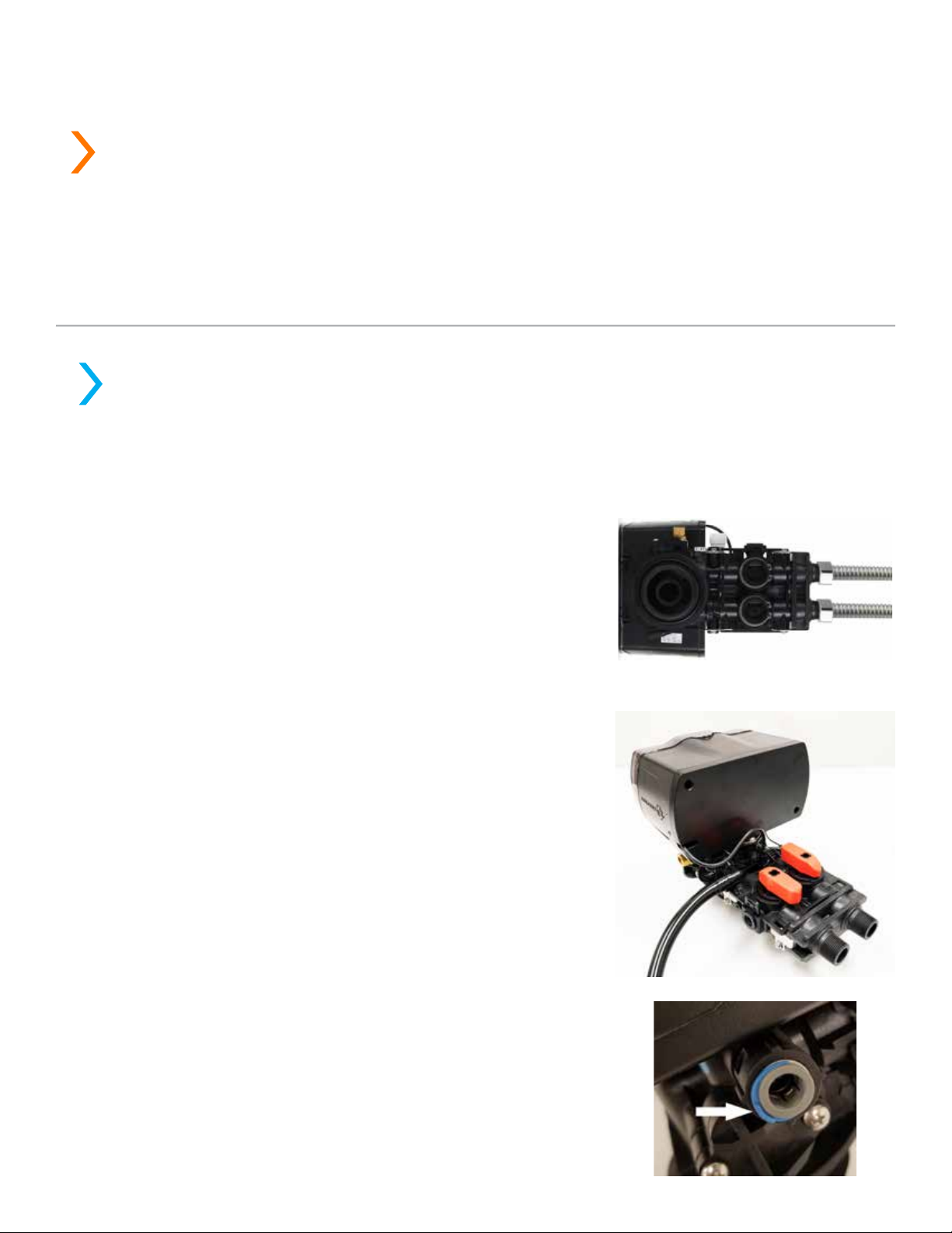
Connecting the System
4
The Aquatrol valve is equipped with 1” male NPT connections. It is recommended that these connections
are made using Teflon tape. The inlet and outlet can be identified on the bypass valve. There are arrows
stamped in the bypass valve showing the flow direction. The arrow pointing toward the valve is the inlet
and the arrow pointing away from the valve is the outlet.
1. Apply the Teflon tape onto the bypass inlet and outlet
fittings.
2. Connect the inlet and outlet of the softener using
appropriate fittings.
3. All piping should be secured to prevent stress on the
bypass valve and connectors.
4. Connect the drain hose to the valve by pressing it into
the Elbow Hose Barb. Run the drain hose to the nearest
laundry tub or floor drain. This can be ran up overhead
or down along the floor. Drain hose should be a minimum
of 1/2”. If running the drain line more than 20 ft linear, it is
recommended to increase the hose size to 3/4” and be sure
there are no sags or “drop” in the hose all the way to the
drain destination.
Note: A direct connection into a waste drain is not
recommended. A physical air gap of at least 1.5” Should be
used to avoid bacteria and wastewater traveling back through
the drain line into the softener.
5. Connect the brine line to the control valve by removing the
blue locking clips on the brine line connectors.
- 9 -
 Loading...