

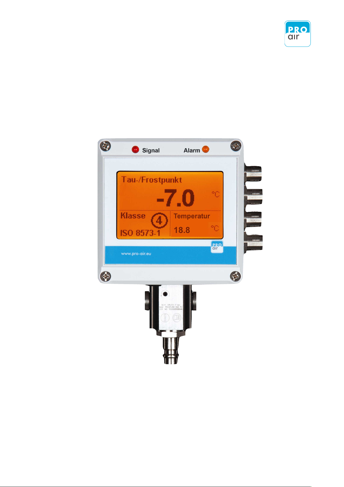
Pressure Dew Point Monitoring Device !
TPK 21 LT
Functional description and operating instructions


Table of contents
1.
Scope of Delivery
1
2.
General dangers and precautions
2
2.1.
Safety instructions for electrical connection
2
2.2.
Safety instructions for compressed air systems
3
3.
Important application notes
4
3.1.
Avoiding damage to the measuring probe
4
3.2.
Calibration and measuring accuracy
4
3.3.
Intended application
5
4.
Humidity measurement in compressed air systems
5
5.
Function
5
6.
Mounting of the device
6
6.1.
Safety instructions
6
6.2.
Application notes
6
6.3.
Procedure for installation
7
6.4.
Mounting
7
7.
Connection at the compressed air network
8
7.1.
Direct stationary assembly at the compressed air line
8
7.2.
Stationary assembly via hose
8
7.3.
Application of a pre-filter / water separator
9
7.4.
Mounting examples
9
7.5.
Adjustment of measurement chamber choke
10
7.6.
Connection of power supply
11
7.7.
TPK Start-up
12
7.8.
For the rarest of the cases…
12
8.
Operation
13
8.1.
Views of unit
13
8.1.1.
Front view
14
8.1.2.
Side view (from the right)
15
8.1.2.1.
Connection to power supply
15
8.1.3.
View (from below)
16

Table of contents
8.2.
Display
16
8.2.1.
Description of display
17
8.2.1.1.
Description of main screen
17
8.2.1.2.
Description info screen
18
8.2.2.
Adjustment of display fields
19
8.2.2.1.
Possible display variation concerning the different fields
20
8.3.
Personalising Password
22
8.4.
Adjustment of national languages
27
8.5.
Information
30
8.6.
Switching the heating(Heater) system On and Off
33
8.7.
Factory settings
36
8.8.
Outputs
39
8.9.
Touchscreen calibration
44
8.10.
Measurement value simulation
47
8.11.
Statistics Reset
52
8.12.
Reset Fault Memory
55
8.13.
Quit Alarm
58
8.14.
Quit Service
61
8.15.
Filter
64
8.16.
Units setting
67
8.17.
Setting the Date / Time
70
8.17.1.
Setting the Date
70
8.17.2.
Setting the Time
74
9.
Configuration of Relay Adjustments
78
9.1.
Setting Source (Output Parameters)
80
9.2.
Setting the Relay Switching Characteristics
81
9.3.
Setting the Limit Values
82
10.
Configuration of Analog Output
84
10.1.
Selection of desired Source (Output Parameter)
86
10.2.
Selection of the desired analog output value
87

Table of contents
10.3.
Configuration of lower analog output value
88
10.4.
Configuration of upper analog output value
89
11.
Configuration of Alarm Output
90
11.1.
Setting of desired alarm value 1
91
11.1.1.
Setting of desired measurement - channel (source)
91
11.1.2.
Setting Pre-alarm
93
11.1.3.
Setting Main-alarm
98
11.1.4.
Setting delay
103
12.
Setting of desired alarm value 2
105
12.1.
Technical Datas
107
13.
Appendix
109
13.1.
Menu structure
110
13.1.1.
Menu item: Main
110
13.1.2.
Menu item: Out
111
13.1.3.
Menu item: Alarm
112
13.2.
System References and Messages
113
13.3.
EG-Conformance Details
114
13.4.
Guarantee
114
13.5
Accessories
115
13.5.1.
Connecting optional accessories
116
13.5.2.
PIN - Assignment for Conctor
117
13.5.3.
Voltage supply from an external source of supply
119
13.6.
Trouble Shooting Guide
120
13.6.1.
The measured value is flow dependent and too high (i.e. too humid)
120
13.6.2.
The measured value is too high (i.e. too humid)
120
13.6.3.
The measured value is too low (i.e. too dry)
121
13.6.4.
The measured value varies significantly
121
13.7.
Service and Calibration
122


1 Scope of Delivery
1
!
Please read the operating instructions before using this device. In addition to the
operating instructions, important information is provided regarding installation,
initial start-up and troubleshooting in each of the relevant chapters.
The pressure dew-point monitor is supplied ready to use. The scope of delivery includes the
AC adaptor, stylus, stylus holder (which may be attached to the dew-point meter) and
relevant operating instructions.
You may also require:
-
Mounting tools, screws and wall plugs
-
6 / 4 mm compressed - air - hose (WARNING! Use only PTFE hoses!).
-
further nipples, reducers and adapter pieces, if the device is to be integrated into a pipeline.
- Electrical accessories for connection to higher-level overriding control devices.
- Optional accessories, such as external indicator lights, terminal adapters and PC cables!
(see accessories overview).
2 General dangers and precautions
2.1 Safety instructions for electrical connection
2
Please read the following warnings prior to initial start-up! The symbols used in the
operating instructions are intended to call your attention to the safety risks. It is not
enough to simply observe the symbol. It is important to read the full text provided in
the safety instructions!
This symbol indicates a potential risk to humans, equipment or the environment. The
information provided must be strictly observed in order to prevent risks.
This symbol indicates important instructions for use and tips that are important in
order to successfully complete tasks, and which must be strictly observed to ensure
good results.
!
!
!
The device must only be supplied with extra-low voltage. The device's other
electrical connections must also only be connected with electronic components
that are operated via an extra-low voltage supply.
Contact with live parts may result in death. Installation of the controller and
maintenance work must therefore only be carried out by trained personnel. The
power supply must be turned off for installation and servicing.
Also avoid touching the plug or any other electronic components when the
power is switched off. Electrostatic phenomena may damage electronic
components.
The product is not intended to control systems with safety-related functions. Even
during normal operation there is a risk of unexpected malfunction, for example
due to a surge or the failure of a component. The user must make sure that no
damage can occur as a result of a malfunction or undefined device status. This
can be achieved, for instance, through the use of redundant components or
safety circuits.
Incorrect screw tightening torques at the connecting terminals or the use of
unsuitable tools can damage the terminal, resulting in damage to insulation or
the contacts. Poorly connected cables can come loose during operation, posing
a considerable risk to safety. Contact resistance at clamp connections results in
increased heat production that can cause a fire to start. Incorrectly wired
connections can destroy electrical components and result in other damage.
!

2.2 Safety instructions for compressed air systems
3
In the case of unforeseen events, the energy stored in compressed air can cause
material damage or result in injury. The risk increases with the operating
pressure of the system. All work must therefore be performed by appropriately
trained personnel. Appropriate care is necessary when performing any work on
the compressed-air system in order to avoid damage!
The loud venting noise produced upon uncontrolled opening of pressurised lines
can damage hearing or startle other people in the vicinity.
At high flow rates, foreign bodies in the air stream can behave like projectiles
and cause injury to the skin or eyes.
The built-in measuring chamber with sensor is designed to handle pressures of
up to 17 bar. This maximum permissible operating pressure must not be
exceeded. Upstream components must be dimensioned according to the
system's operating pressure and temperature.
The warranty will become null and void if the sensor housing is opened, the
sintered cap removed or in the event of improper handling or the use of force.
!

3 Important application notes
3.1 Avoiding damage to the measuring probe
3.2 Calibration and measuring accuracy
4
Measuring devices are sensitive and must be handled with care:!
Avoid shocks, impacts and vibrations.
The sintered filter protects the sensor against mechanical stress and contamination.
Do not remove the filter. Only use the probe if the sintered filter is undamaged!
Prior to installation, check that there is no condensation, oil or dirt at the measuring
point! Should this be the case, repair and dry out the system!
The measuring system is not suitable for use with compressed air with a high oil content,
as directly covering the sensor with a film of oil impairs its response, blocks the pores of
the filter and damages the filter choke.
As a rule of thumb: If you have any questions, contact the manufacturer.
Do not attempt to experiment with the device as you may cause faults and damage
to occur!
!
Prior to delivery, the pressure dew-point sensor is adjusted and tested by means of a complex
calibration procedure involving several temperatures and humidity points. It is not possible for
the end user to calibrate the device.
Please observe the permissible temperature range for use. Excessive temperatures reduce the
measuring accuracy. The probe will be damaged if the temperature limit is exceeded.
The specified data, in particular the desired measuring accuracy, are valid at a temperature of
20°C. In principle, the lower the temperature at the sensor, the more accurate the measurement
result. If possible, measurements should be taken in a cool area, or the gas should be cooled to
ambient temperature.
With proper use, the probe will have a lifespan of many years. Nevertheless, to prevent errors,
it is important that the sensor be calibrated once a year, according to the manufacturer's
specifications. This particularly applies when the probe is used in critical applications within the
lower dew-point measuring range.

3.3 Intended application
4 Humidity measurement in compressed air systems
5 Function
5
The new TPK 21 LT is intended to be used to measure the pressure dew points, pressure
and temperature of clean, oil-free compressed air, which is free of any abrasive,
corrosive, caustic, toxic, flammable and combustible components. For the scope of
application and the calibrated measuring range, please refer to the technical data.
!
In the industrial sector, quality requirements for compressed air are becoming ever stricter.
Humidity and condensation are not permitted in compressed air and often cause damage to
machines and lead to reduced production quality. Compressed-air dryers are commonly used.
When used correctly, these reduce the moisture content of the air and ensure the production
of high-quality compressed air.
However, problems with dryers are often detected very late on, usually when damage has
already occurred. A large quantity of humidity will have already entered the compressed-air
network, and considerable efforts will be required to dry the system out again. The high
quality standards of the industrial sector call for continuous, reliable and stable long-term
monitoring of the humidity content. This is the only way to detect problems early, before any
damage has occurred.
With its large measuring range, the new TPK series is the ideal measuring system for
monitoring refrigeration, adsorption and membrane dryers. The device is primarily intended
for stationary applications but is also suitable for use as a portable measuring device thanks
to its simple connection system.
If compressed air is not dried before being fed into the compressed-air network, significant
quantities of condensate can form in the pipe network, resulting in the malfunctioning of
valves and pneumatic components, ultimately leading to loss of production. The pressure dew
point in compressed-air systems is therefore a key factor in determining air quality and should
be measured in all systems.
The new TPK series offers the ideal device for monitoring compressed-air quality (humidity,
pressure and temperature) and giving timely warning, before any damage has occurred.
The series has a built-in measuring chamber with a protection filter and filter choke, as well as
a plug connection for a 7.2 mm NW compressed-air socket. Power is supplied via the mains
adapter provided. Initial set-up of the measuring system therefore requires no interference
with the compressed-air network, nor any electrical installation work. Alternatively, the
measuring system can be installed on the compressed-air line to avoid the loss of scavenging
air.

6 Mounting of the device
6.1 Safety instructions
6.2 Application notes
6
The device must only be used for its intended purpose.
Installation of the controller and maintenance work must only be carried out by
trained personnel. The power supply must be turned off for installation and
servicing. The applicable safety regulations must be observed! All work on the
compressed-air system must be carried out under pressure-free conditions.
The device must only be operated with extra-low voltage. This also applies to all
external connections, such as the relay outputs.
!
The air quality at the site of installation must be checked prior to assembly. Repairs
must be made to the system in the case of any water or oil leakages. Contact with
large quantities or water or oil may damage the sensor.
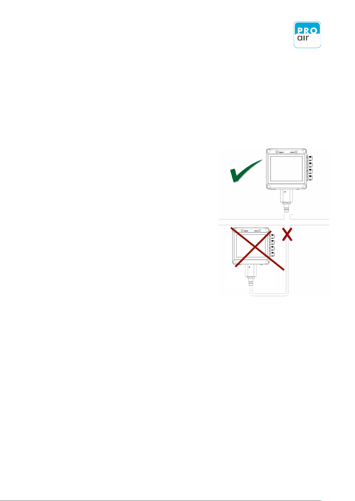
The compressed air must be drawn from the upper side of the pipe. The device
must be mounted above the compressed-air line so that any condensation
produced in the event of failure cannot flood the measuring chamber.
Use only suitable materials. The materials used must be impermeable to water
vapour. Therefore please do not use regular polyurethane hoses! The only
recommended material for flexible hose connections is PTFE ("TEFLON"). All metals
are suitable down to -30°Ctpd. Below this, stainless steel is the preferred choice.
Avoid using excessively long sample-gas lines or unnecessary connectors.
The sensors on upstream components must not diffuse water vapour into the
surrounding environment! Please use only high-quality components, e.g. ball
valves with PTFE seals.
Carefully seal all points of connection with the sensor or measuring chamber.
However, never use anaerobic liquid sealants, as these maydamage the sensor
element!
Heavy particle loads will clog the filter or filter choke over time, resulting in a
delayed response. In critical cases, an additional fine filter must be installed
upstream of the measuring device.
!

6.3 Procedure for installation
6.4 Mounting
7
If using compressed air of unknown quality, use a condensate separator or particle
filter. Additional components must be suitable for the intended use!
In EMC-critical environments the measuring chamber should be electrically isolated
from the metal pipes of the compressed-air network. The use of a PTFE or
Polypropylene double nipple is an example of a suitable solution.
Installation involves the following steps:
- Mounting of the device, if necessary.
- Connection to the compressed-air network
- Adjustment of the filter choke, if necessary
- Connection to the power supply
- Initial start-up
- Setting of the switching points
- Testing and function control
If the device is operated as a portable device or is connected using a standard coupling, as
described below, no further mounting is required.
When mounting onto a machine, the device can be kept level by using mounting brackets. A
drilling template can be found in the appendix of this manual.
7 Connection at the compressed air network
7.1 Direct stationary assembly at the compressed air line
7.2 Stationery assembly via hose
8
In the case of stationary use, the device is usually installed downstream of the dryer/filter,
enabling the entire system to be monitored. It may also be installed at any point further
downstream in the distribution system in order to
monitor subsegments or the air supply entering a
particular machine.
In order to avoid unnecessary compressed-air
consumption through loss of scavenging air, the
measuring chamber with the sensor should preferably
be directly installed into the compressed-air line.
To prevent the accumulation of condensation in the
event of a fault, the measuring chamber must be
screwed vertically into the line from the top.
Extremely high flowrates or sudden pressure changes
should be avoided, as these may damage the sensor
element.
If a spur line is required for connection, this should
only be a few centimetres long, otherwise the
response will be impaired, especially at low dew-point
values. If longer spur lines are used, the choke must be opened onto the measuring chamber
and set to approximately 60 l/h.
Long, vertical spur lines impair the response or result in incorrect measured values.
The device may be alternatively connected to the compressed-air supply via a Teflon connection
line through the built-in measuring chamber with choke. To ensure correct functioning and
guarantee measuring accuracy there must be a throughflow of air. The basic flow rate can be set
at the choke. In order to avoid unnecessarily high loss of scavenging air, the flow at the rated
pressure can be set to 60 l/h by means of a flow meter. Check from time to time that there is air
flowing at the adjusting screw. If the choke is closed, the measuring device displays values that
are too high or triggers an alarm

7.3 Application of a pre-filter / water separator
7.4 Mounting examples
9
Depending on the state of the compressed-air system and distribution network, it is possible for
dirt, condensate or oil to leak out from the measuring point. In order to avoid damage to the
probe in such critical areas of application, a water separator with a fine filter can be connected
upstream of the device. The upstream components must not alter the moisture content of the air or
unduly impair the response. We can provide you with a list of suitable components upon request.
The device is suitable for a variety of applications. The flexible design of the measuring chamber
allows it to be easily adapted to the intended use:
Connection to a 7.27,2 mm NW quick coupler:
This connection can be quickly and easily performed
within minutes, without any complex installation.
-
An NW 7.2 plug-in nipple with a 3/8" thread is
connected to the underside of the device.
-
The device is connected directly to the coupling, and no
further mounting is required.
-
The choke is set to approximately 60 l/h (factory setting,
as delivered).
!
Permanent connection to a compressed air line:
This type of connection is ideal when there is only a short
distance to the main line because no purge air is consumed.
-
Underneath, a 3/8" double nipple is mounted and
connects to the pipe.
-
In the case of direct connection to a main line, the choke is
closed.
-
For greater connection distances or spur lines, the choke is
set to approximately 60 l/h.

7.5 Adjustment of measurement chamber choke
10
Connection via a compressed-air hose:
This connection variant is ideal, for example, if the device is
intended for portable use or mounted onto a machine or
panel.
-
Underneath, the 3/8" thread is fitted onto a 6/4 mm
hose.
-
The choke is set to approximately 60 l/h for stationary
applications (factory setting, as delivered). If used as a
portable device for rapid measurements the setting should
be changed to approximately 240 l/h.
-
NOTE: Use only PTFE hose for the connection.
The choke's factory default setting is a 60 l/h basic flow rate at a pressure of 10 bar. So long
as the choke has not been adjusted, no adjustment is usually required, provided that this is the
desired flow rate.
Depending on the type of connection, the choke can be closed to avoid the loss of scavenging
air. This is done by fully tightening the Allen screw using the socket spanner provided.
If used as a portable device for rapid measurements the basic flow rate should be set to
approximately 240 l/h. To do this, the choke is opened until the screw is in line with the top
edge of the measuring chamber. The venting noise can clearly be heard in this position. The
response is faster with a high basic flow rate.
To reset the choke to 60 l/h for stationary applications, a flow meter is required, which is fitted
over the screw using a flat seal. The desired flow rate is achieved by repeatedly adjusting and
checking the flow.
Precise adjustment of the desired flow rate is particularly important in the case of stationary
applications, because too high a flow rate results in high operating costs.
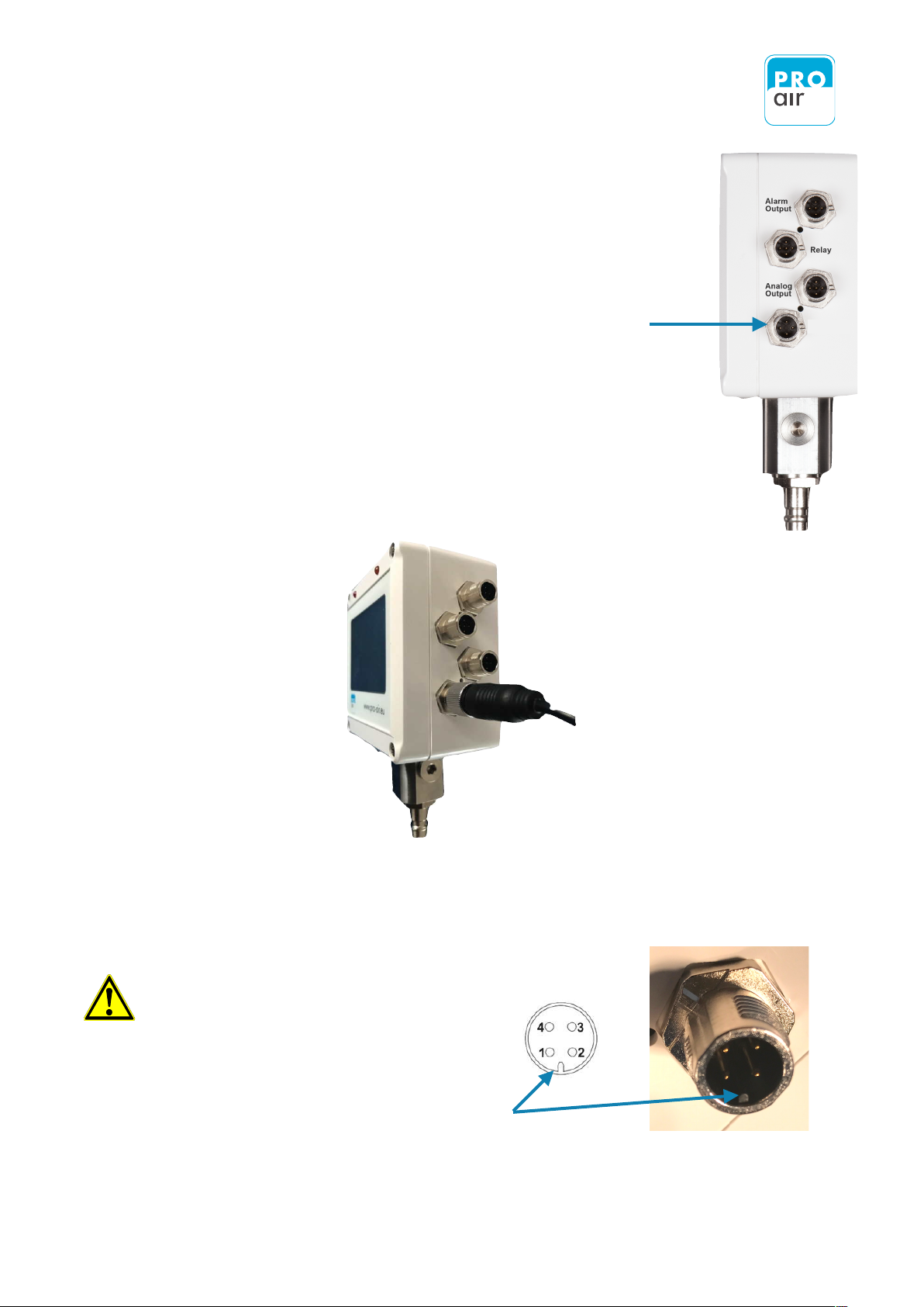
7.6 Connection of power supply
11
The device is operated with extra-low voltage. A suitable mains adapter is
provided.
The power supply unit is plugged into the lower M12 socket.
No complex electrical installation is necessary, and the device is immediately
ready for operation
The AC adaptor with Europlug is of a high-quality design with a wide-range
input. It is suitable for a 90 - 240 V power supply and is therefore suitable for
Europe-wide use.
How to connect with mains adapter
Do not try to force the connector
when plugging it in.
!
Connection Diagram FGPx remote probe
Follow the guidelines for plugs and
sockets!!
DC 24 V

7.7 TPK Start-up
7.8 For the rarest of the cases…
12
The device immediately starts up when plugged into the power supply. There are no other
switches. The first measured values are displayed immediately after turning on the device. The
measured values are likely to fall immediately following connection to the compressed-air network.
The values will stabilise after a short time. Depending on the system, the following values should
be set:
- For refrigeration dryers: approx. 0 to 7°Ctdp
- For an additional membrane dryer: approx. -20 to -10°C
If the device does not start up, please check the following points:
- Is power arriving at the mains socket ?
- Is the mains plug correctly plugged in ?
- Is the M12 socket of the power supply correctly connected to the device ?
- Does the power supply unit deliver 24 V DC voltage (external power supply units ?
If you have examined all the possible causes and still have not managed to rectify the
malfunction, please immediately contact our customer service department. Do not
open the device, as this will invalidate the warranty claim !
!
8 Operation
8.1 Views of unit
13
General information on the description of the operating procedures
All images of the displays, numerical values and configurations are used by way of
example to explain and clarify the information provided. The actual display on your
device may differ according to the selected settings or ambient conditions.
!
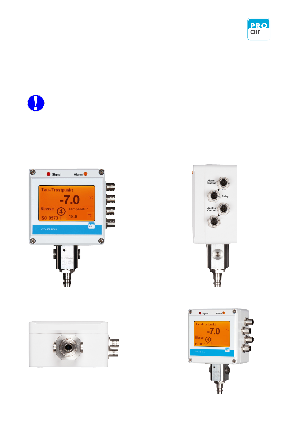
Side view
(from the right)
Front view
View
(from below)
View
Isometric
DC 24 V
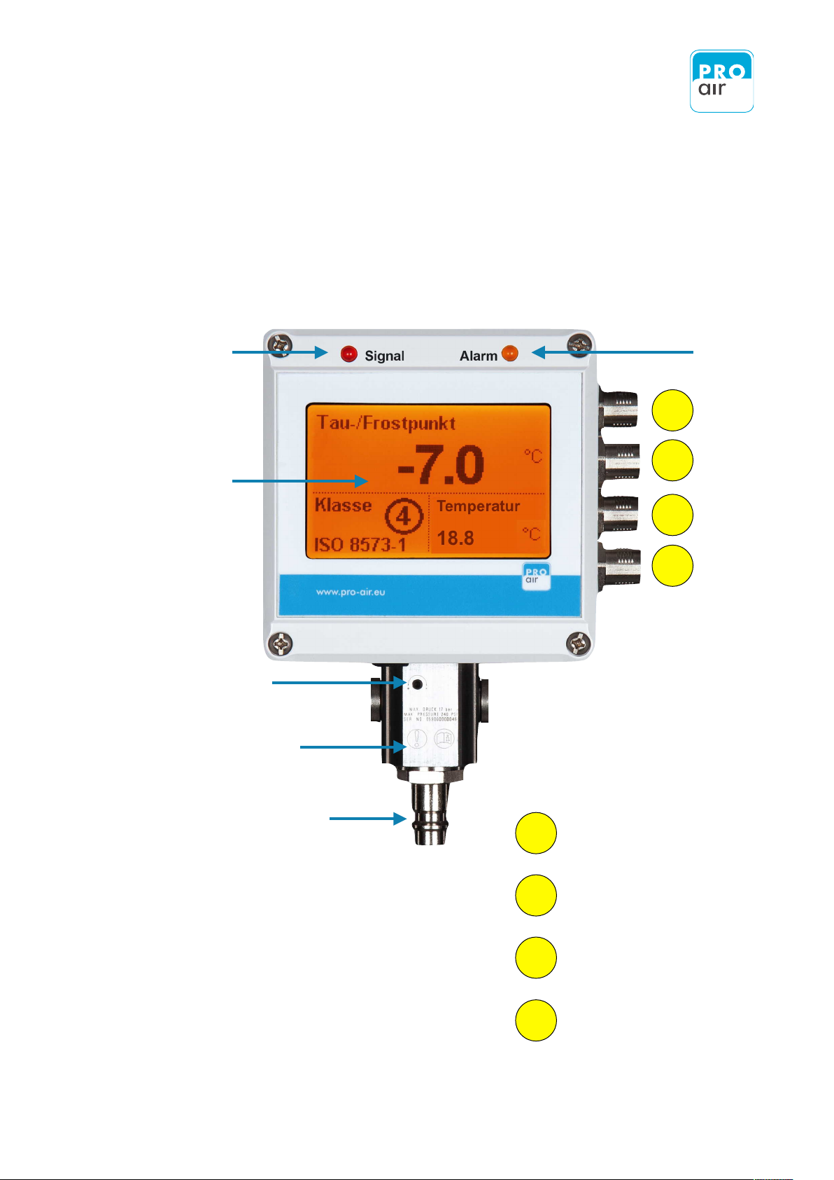
8.1.1 Front view
14
Warning- / Signal LED
LCD touch-display
Choke-adjustment screw
Built-in measuring chamber
Standard NW 7,2 plug-in nipple
(suitable for direct connection to the
compressed-air coupling)
Alarm LED
1
2
3
4
Assignment of the M-12 connection sockets:
Alarm output connection
Relay output connection
Analog output connection
Connection for external mains
adapter
1
2
3
4
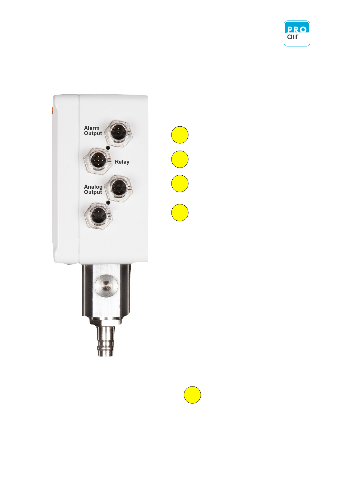
8.1.2 Side View (from the right)
8.1.2.1 Connection to power supply
15
Assignment of the M-12 connection sockets:
Connection for external mains adapter
Analog output connection
Relay output connection
Alarm output connection
1
2
3
4
The external mains adapter can be connected to the lower M-12 connection socket.
4
DC 24 V
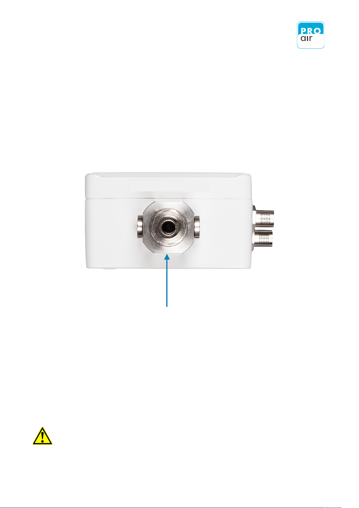
8.1.3 View (from below)
8.2 Display
16
Connection to the compressed-air network
The built-in touch display is a monochrome FSTN dot-matrix display with white
backlight and a resolution of 160 x 110.
All values may be set or changed accordingly via the screen using the stylus provided
or with careful finger movements.
Caution: The use of pointed objects, such as ballpoint pens or pencils, can
destroy the display and invalidate the warranty!
!
8.2.1 Description of Display
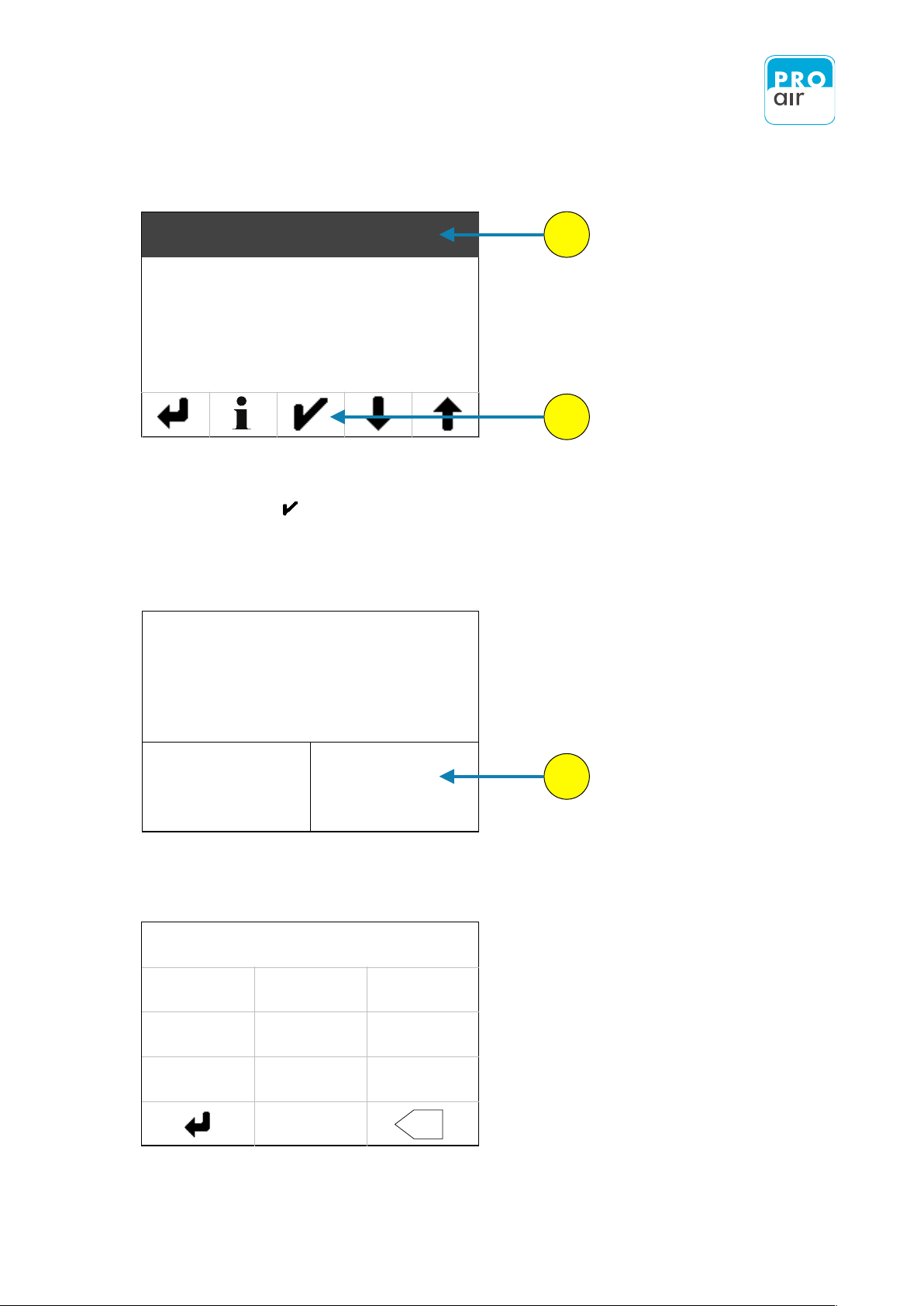
8.2.1.1 Description of the Main Screen
17
Once the device is connected to the power supply, a welcome screen with the logo
and company name briefly appears and then the main screen is displayed.
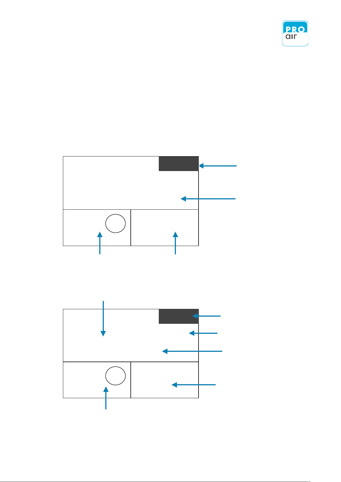
The screen is divided into 3 fields (a main field and 2 smaller fields).
All fields can be individually adjusted.
Main Screen
Info Screen
Field 1
Field 2
displays the physical measuring value
Info Screen (temporary), please notice
next page
Unit actual measuring value
Currently measured value
This field shows a further current
measured value with physical unit.
(individually adaptable)
This field shows for example the actual humidity class acc.
to ISO 8573-1 or a further measured value with physical
unit. (individually adaptable)
Class
4
ISO 8573-1
Temperature
22.1
o
C
o
C
Dew-/Frostpoint
- 7.0
H HOLD
Class
4
ISO 8573-1
Temperature
22.1
o
C
o
C
Dew-/Frostpoint
- 7.0
H HOLD

8.2.1.1 Description Info Screen
18
After restarting the device or during bake-out of the sensor an "Information Screen" is
displayed in the upper right-hand corner of the display with the following background.
Dew points in the range of -60 to -20°C at room temperature correspond to relative
humidity values of 0.08 to 5.37% RH. To ensure accurate measurement at the lowest
humidity values, the slightest drift effect of the humidity sensor element must be
compensated for.
Moreover, in order to guarantee the long-term stability of the dew-point sensor the sensor
element is periodically baked out. The sensor is heated every 13 h for approximately
5 minutes and then allowed to cool down to ambient temperature.
During heating "HHOLD" appears on the display, and "CHOLD" is indicated during
cooling. The operation is indicated on the display:
The „Info Screen“ displays the current auto-calibration status:
H HOLD: Heat (The sensor element is being heated)
HOLD (The measured value is being saved)
C HOLD: Cold (The sensor is cooling down)
HOLD (The measured value is being saved)
H HOLD
C HOLD
!
Bake-out is performed every time the device is connected to the mains supply, then
every 13 h. During the entire cycle, the last measured values are retained and are
qualitatively available at the outputs. No further measurements are made during the
heating phase. Therefore no alarm signal will be emitted during this period of time in
the event that a maximum permissible value is exceeded. Only after the heating/
cooling cycle has finished will the device resume measurement and alarm evaluation.
8.2.2 Adjustment of display fields
19
To adjust one of the fields according your specific needs, select the desired field by
tapping it with the stylus provided or your finger.
The display now appears as follows (the main field has been selected as an example).
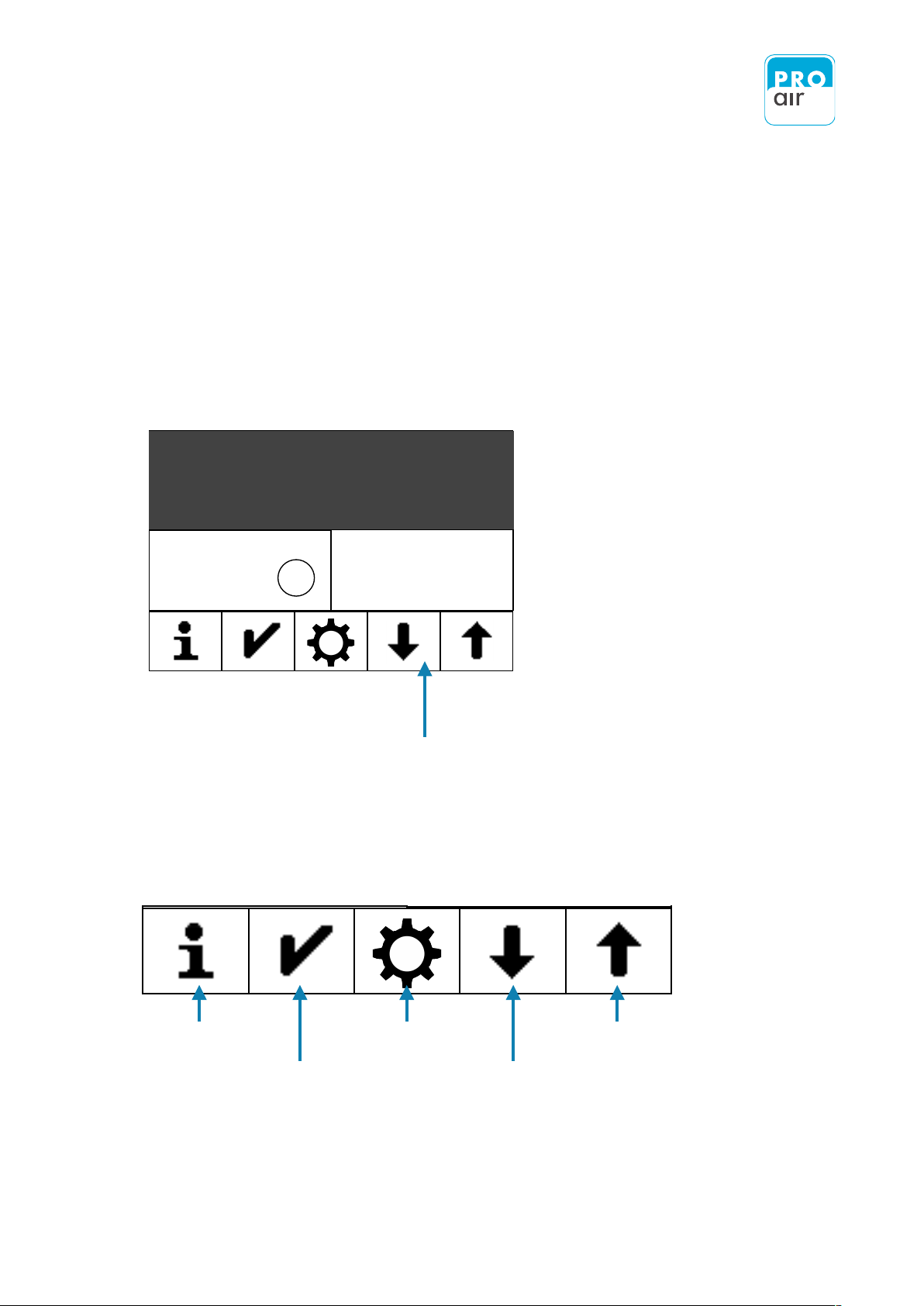
In the lower third of the display an
additional menu bar appears that
allows further settings to be defined.
Klasse
ISO 8573-1
1.17
bar
Tau-/Frostpunkt
- 7.0
o
C
4
Druck
Information
Settings
Scroll - up
Enter - Confirm
Scroll - down
Class
ISO 8573-1
22.1
o
C
Dew-/Frostpoint
- 7.0
o
C
4
Temperature

8.2.2.1 Possible display variation concerning the different fields
20
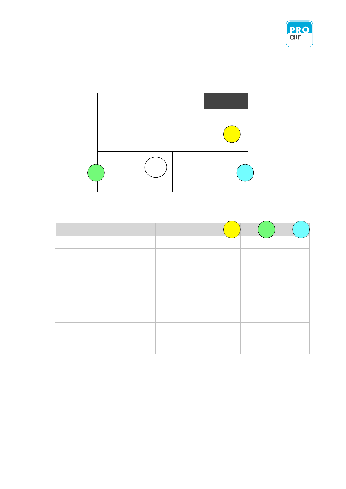
Each field can be adjusted on site to meet your specific needs.
The procedure is as follows:
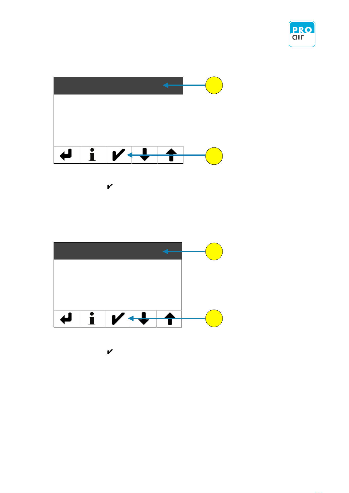
1. Select the desired field on the display (the background turns dark and control
keys appear at the bottom of the display).
2. Scroll up or down to the desired setting using the two arrow keys.
3. Confirm the setting using the "Confirm" key. The display jumps back to the
home screen, where the modified field contents can be seen.
example: Changing the display value in the main field
1
2
3
Select the main field
Scroll up or down to the desired display value
Confirm the desired value
Class
ISO 8573-1
22.1
o
C
Dew-/Frostpoint
- 7.0
o
C
4
Temperature
1
21
Physical variable
Possible units
Field
Field
Field
Pressure dew point / Frostpoint
o
C, oF
X
Alarm values (settings)
Pre-alarm / Main alarm /
Service
X
X
Date / Time
Various settings are
possible in the main
menue
X
X
Relay - settings
On/Off
X
X
Statistics
Minimum- / Maximum- /
mean value
X
X
Temperature
o
C, oF
X
Relative Humidity
%
XXX
Compressed air class according to
ISO 8573-1
X
123
Class
4
ISO 8573-1
Temperature
22.1
o
C
o
C
Dew-/Frostpoint
- 7.0
H HOLD
1
3
2

8.3 Personalising Password
22
The password can be personalised. The factory default is 111111.
CAUTION: Please make a note of the new password. If the password is forgotten, the
device must be reset to the factory settings. This will result in the loss of all settings!
!
The procedure is as follows:
1. Select one of the three segment fields (the background turns dark and control keys appear
at the bottom of the display).
2. Select „Settings“
The following display appears:
PIN
- - - - - -
123
456
789
0
X
3. Enter your personal PIN code (if it has already been changed). If the device is
still in its factory settings, key in 111111 .
1
2
3
Class
ISO 8573-1
22.1
o
C
Dew-/Frostpoint
- 7.0
o
C
4
Temperature
23
You are now in the settings menu (Level 1).
4. If the „Main“ field is not already highlighted, select the field and
confirm with .
Under the menu item „Main“ you will find all of the device settings, as well as the settings for
displaying the measured values.
The following display of the settings menu appears (Level 2):
6. If the „Device“ setting field is not already highlighted, select the field and
confirm with .
Under the menu item „Device“ " you will find all of the basic settings for the device.
4
5
6
7
Main
Out
Alarm 1
Alarm 2
Device
Filter
Unit
Clock
24
The following display of the settings menu appears (Level 3):
8. If the „Password“ field is not already highlighted, select the field and
A display will appear with the following warning:
Select "Yes" to confirm and continue.
8
9
10
Password
Language
Info
Heater
No
Yes
If you forget the password, you have to send
the device to our service to reset it to the
factory default state. Are you sure ?
PIN
_ _ _ _ _ _
123
456
789
0
X

25
If the password has already been changed, enter it now.
If the device is still in its factory settings, enter 111111.
A screen appears that allows you to enter a password of your choice.
Please confirm the new password
!
The required input is indicated in the Password menu in the upper left corner of the
display.
Current PIN
_ _ _ _ _ _
123
456
789
0
X
Confirm PIN
_ _ _ _ _ _
123
456
789
0
X
New PIN
_ _ _ _ _ _
123
456
789
0
X

26
After correctly entering the new password, the display automatically jumps back to the
following display.
The„Back“ key takes you back to the previous level
until you are back at the home screen.
Password
Language
Info
Heater

8.4 Adjustment of national languages
27
The currently available languages are English, German and French. These can be easily
selected via the menu.
The procedure is as follows:
1. Select one of the three segment fields (the background turns dark and control keys appear at
the bottom of the display).
2. Select „Settings“
The following display appears:
PIN
- - - - - -
123
456
789
0
X
3. Enter your personal PIN code (if it has already been changed). If the device is
still in its factory settings, key in 111111 .
1
2
3
Class
ISO 8573-1
1.17
bar
Dew-/Frostpoint
- 7.0
o
C
4
Pressure
22
The password can be personalised. The factory default is 111111.
CAUTION: Please make a note of the new password. If the password is forgotten, the
device must be reset to the factory settings. This will result in the loss of all settings!
!
The procedure is as follows:
1. Select one of the three segment fields (the background turns dark and control keys appear
at the bottom of the display).
2. Select „Settings“
The following display appears:
PIN - - - - - -
1 2 3
4 5 6
7 8 9
0
X
3. Enter your personal PIN code (if it has already been changed). If the device is
still in its factory settings, key in 111111 .
1
2
3
Class
ISO 8573-1
22.1
o
C
Dew-/Frostpoint
- 7.0
o
C
4
Temperature

28
You are now in the settings menu (Level 1).
4. If the „Main“ field is not already highlighted, select the field and
confirm with .
Under the menu item „Main“ you will find all of the device settings, as well as the settings for
displaying the measured values.
The following display of the settings menu appears (Level 2):
6. If the „Device“ setting field is not already highlighted, select the field and
confirm with .
Under the menu item „Device“ " you will find all of the basic settings for the device.
4
5
6
7
Main
Out
Alarm 1
Alarm 2
Device
Filter
Unit
Clock
23
You are now in the settings menu (Level 1).
4. If the „Main“ field is not already highlighted, select the field and
confirm with .
Under the menu item „Main“ you will find all of the device settings, as well as the settings for
displaying the measured values.
The following display of the settings menu appears (Level 2):
6. If the „Device“ setting field is not already highlighted, select the field and
confirm with .
Under the menu item „Device“ " you will find all of the basic settings for the device.
4
5
6
7
Main
Out
Alarm 1
Alarm 2
Device
Filter
Unit
Clock

29
The following display of the settings menu appears (Level 3):
8. If the „Language“ field is not already highlighted, select the field and
confirm with. .
Select the desired language (the field will be highlighted) and confirm your choice with .
The „Back“ key takes you back to the previous level until you are back at the home screen.
8
9
Password
Language
Info
Heater
English
Deutsch
Français
10

8.5 Information
30
The menu item „Information“ shows all the important device informations at a glance.
The procedure is as follows:
1. Select one of the three segment fields (the background turns dark and control keys appear
at the bottom of the display).
2. Select „Settings“
The following display appears:
PIN
- - - - - -
123
456
789
0
X
3. Enter your personal PIN code (if it has already been changed). If the device is
still in its factory settings, key in 111111 .
1
2
3
Class
ISO 8573-1
1.17
bar
Dew-/Frostpoint
- 7.0
o
C
4
Pressure
22
The password can be personalised. The factory default is 111111.
CAUTION: Please make a note of the new password. If the password is forgotten, the
device must be reset to the factory settings. This will result in the loss of all settings!
!
The procedure is as follows:
1. Select one of the three segment fields (the background turns dark and control keys appear
at the bottom of the display).
2. Select „Settings“
The following display appears:
PIN - - - - - -
1 2 3
4 5 6
7 8 9
0
X
3. Enter your personal PIN code (if it has already been changed). If the device is
still in its factory settings, key in 111111 .
1
2
3
Class
ISO 8573-1
22.1
o
C
Dew-/Frostpoint
- 7.0
o
C
4
Temperature

31
You are now in the settings menu (Level 1).
4. If the „Main“ field is not already highlighted, select the field and
confirm with .
Under the menu item „Main“ you will find all of the device settings, as well as the settings for
displaying the measured values.
The following display of the settings menu appears (Level 2):
6. If the „Device“ setting field is not already highlighted, select the field and
confirm with .
Under the menu item „Device“ " you will find all of the basic settings for the device.
4
5
6
7
Main
Out
Alarm 1
Alarm 2
Device
Filter
Unit
Clock
23
You are now in the settings menu (Level 1).
4. If the „Main“ field is not already highlighted, select the field and
confirm with .
Under the menu item „Main“ you will find all of the device settings, as well as the settings for
displaying the measured values.
The following display of the settings menu appears (Level 2):
6. If the „Device“ setting field is not already highlighted, select the field and
confirm with .
Under the menu item „Device“ " you will find all of the basic settings for the device.
4
5
6
7
Main
Out
Alarm 1
Alarm 2
Device
Filter
Unit
Clock

32
The following display of the settings menu appears (Level 3):
8. If the „Info“ field is not already highlighted, select the field and
confirm with. .
A screen is displayed which provides you with an overview of the most important information.
8
Password
Language
Info
Heater

8.6 Switching the heating (Heater) system On and Off
33
The menu „Heater“ allows you to turn the sensor heating system on or off.
With some primary control systems the heating process can lead to system malfunctions. This
menu enables you to turn off the factory-set heating process.
With typical use in the upper dew-point range of over -10°C the trace heater should be
switched on. In the case of measurements at below -10°C, the trace heater may be switched
off if necessary.
The procedure is as follows:
1. Select one of the three segment fields (the background turns dark and control keys appear
at the bottom of the display).
2. Select „Settings“
The following display appears:
PIN
- - - - - -
123
456
789
0
X
3. Enter your personal PIN code (if it has already been changed). If the device is
still in its factory settings, key in 111111 .
1
2
3
Class
ISO 8573-1
1.17
bar
Dew-/Frostpoint
- 7.0
o
C
4
Pressure
22
The password can be personalised. The factory default is 111111.
CAUTION: Please make a note of the new password. If the password is forgotten, the
device must be reset to the factory settings. This will result in the loss of all settings!
!
The procedure is as follows:
1. Select one of the three segment fields (the background turns dark and control keys appear
at the bottom of the display).
2. Select „Settings“
The following display appears:
PIN - - - - - -
1 2 3
4 5 6
7 8 9
0
X
3. Enter your personal PIN code (if it has already been changed). If the device is
still in its factory settings, key in 111111 .
1
2
3
Class
ISO 8573-1
22.1
o
C
Dew-/Frostpoint
- 7.0
o
C
4
Temperature

34
You are now in the settings menu (Level 1).
4. If the „Main“ field is not already highlighted, select the field and
confirm with .
Under the menu item „Main“ you will find all of the device settings, as well as the settings for
displaying the measured values.
The following display of the settings menu appears (Level 2):
6. If the „Device“ setting field is not already highlighted, select the field and
confirm with .
Under the menu item „Device“ " you will find all of the basic settings for the device.
4
5
6
7
Main
Out
Alarm 1
Alarm 2
Device
Filter
Unit
Clock
23
You are now in the settings menu (Level 1).
4. If the „Main“ field is not already highlighted, select the field and
confirm with .
Under the menu item „Main“ you will find all of the device settings, as well as the settings for
displaying the measured values.
The following display of the settings menu appears (Level 2):
6. If the „Device“ setting field is not already highlighted, select the field and
confirm with .
Under the menu item „Device“ " you will find all of the basic settings for the device.
4
5
6
7
Main
Out
Alarm 1
Alarm 2
Device
Filter
Unit
Clock

35
The following display of the settings menu appears (Level 3):
8. If the „Heater“ field is not already highlighted, select the field and
confirm with .
The following display appears, which allows you to determine the status of the heating system
by selecting "On" or "Off".
Confirm your entry with .
The „Back“ key takes you back to the previous level until you are back at the home screen.
Password
Language
Info
Heater
OFF
ON

8.7 Factory Settings
36
The menu item "Factory settings" can be used to reset the device to its factory default settings.
CAUTION! This will result in the loss of all settings!
!
The procedure is as follows:
1. Select one of the three segment fields (the background turns dark and control keys appear
at the bottom of the display).
2. Select „Settings“
The following display appears:
PIN
- - - - - -
123
456
789
0
X
3. Enter your personal PIN code (if it has already been changed). If the device is
still in its factory settings, key in 111111 .
1
2
3
Class
ISO 8573-1
1.17
bar
Dew-/Frostpoint
- 7.0
o
C
4
Pressure
22
The password can be personalised. The factory default is 111111.
CAUTION: Please make a note of the new password. If the password is forgotten, the
device must be reset to the factory settings. This will result in the loss of all settings!
!
The procedure is as follows:
1. Select one of the three segment fields (the background turns dark and control keys appear
at the bottom of the display).
2. Select „Settings“
The following display appears:
PIN - - - - - -
1 2 3
4 5 6
7 8 9
0
X
3. Enter your personal PIN code (if it has already been changed). If the device is
still in its factory settings, key in 111111 .
1
2
3
Class
ISO 8573-1
22.1
o
C
Dew-/Frostpoint
- 7.0
o
C
4
Temperature

37
You are now in the settings menu (Level 1).
4. If the „Main“ field is not already highlighted, select the field and
confirm with .
Under the menue item „Main“ you will find all of the device settings, as well as the settings for
displaying the measured values.
The following display of the settings menu appears (Level 2):
6. If the „Device“ setting field is not already highlighted, select the field and
confirm with .
Under the menue item „Device“ " you will find all of the basic settings for the device.
4
5
6
7
Main
Out
Alarm 1
Alarm 2
Device
Filter
Unit
Clock
23
You are now in the settings menu (Level 1).
4. If the „Main“ field is not already highlighted, select the field and
confirm with .
Under the menu item „Main“ you will find all of the device settings, as well as the settings for
displaying the measured values.
The following display of the settings menu appears (Level 2):
6. If the „Device“ setting field is not already highlighted, select the field and
confirm with .
Under the menu item „Device“ " you will find all of the basic settings for the device.
4
5
6
7
Main
Out
Alarm 1
Alarm 2
Device
Filter
Unit
Clock

38
The following display of the settings menu appears (Level 3):
8. Please scroll down with „Scroll-down“ key until you see the following screen.
9. If the „Factory Setting“ field is not already highlighted, select the field and
confirm with .
The „Back“ key takes you back to the previous level until you are back at the home screen.
Select „Yes“ if you want to return the device to
its factory settings (NOTE: all saved data will
be lost) and confirm by pressing „Enter“ .
!
8
9
Password
Language
Info
Heater
Factory Settings
Outputs
Touchscreen Calibration
Manual Value Override
Ye s
No

8.8 Outputs
39
This menu item is used to test the relay and alarm functions. Each output can be switched
manually.
The procedure is as follows:
1. Select one of the three segment fields (the background turns dark and control keys appear
at the bottom of the display).
2. Select „Settings“
The following display appears:
PIN
- - - - - -
123
456
789
0
X
3. Enter your personal PIN code (if it has already been changed). If the device is
still in its factory settings, key in 111111 .
1
2
3
Class
ISO 8573-1
1.17
bar
Dew-/Frostpoint
- 7.0
o
C
4
Pressure
22
The password can be personalised. The factory default is 111111.
CAUTION: Please make a note of the new password. If the password is forgotten, the
device must be reset to the factory settings. This will result in the loss of all settings!
!
The procedure is as follows:
1. Select one of the three segment fields (the background turns dark and control keys appear
at the bottom of the display).
2. Select „Settings“
The following display appears:
PIN - - - - - -
1 2 3
4 5 6
7 8 9
0
X
3. Enter your personal PIN code (if it has already been changed). If the device is
still in its factory settings, key in 111111 .
1
2
3
Class
ISO 8573-1
22.1
o
C
Dew-/Frostpoint
- 7.0
o
C
4
Temperature

40
You are now in the settings menu (Level 1).
4. If the „Main“ field is not already highlighted, select the field and
confirm with .
Under the menue item „Main“ you will find all of the device settings, as well as the settings for
displaying the measured values.
The following display of the settings menu appears (Level 2):
6. If the „Device“ setting field is not already highlighted, select the field and
confirm with .
Under the menue item „Device“ " you will find all of the basic settings for the device.
4
5
6
7
Main
Out
Alarm 1
Alarm 2
Device
Filter
Unit
Clock
23
You are now in the settings menu (Level 1).
4. If the „Main“ field is not already highlighted, select the field and
confirm with .
Under the menu item „Main“ you will find all of the device settings, as well as the settings for
displaying the measured values.
The following display of the settings menu appears (Level 2):
6. If the „Device“ setting field is not already highlighted, select the field and
confirm with .
Under the menu item „Device“ " you will find all of the basic settings for the device.
4
5
6
7
Main
Out
Alarm 1
Alarm 2
Device
Filter
Unit
Clock

41
The following display of the settings menu appears (Level 3):
8. Please scroll down with „Scroll-down“ key until you see the following screen.
9. If the „Outputs“ field is not already highlighted, select the field and
confirm with .
8
9
Password
Language
Info
Heater
Factory Settings
Outputs
Touchscreen Calibration
Manual Value Override

42
Two choices appear („Output“ and „State“)
10. If the „Output“ field is not already highlighted, select the field and
confirm with .
11. A list will appear of all the test possibilities.
12. Scroll up or down using the "Scroll-down" and "Scroll-up" keys until you find the
output value that you wish to test.
None
Relay 1
Relay 2
Pre Alarm
Main Alarm
Analog Out
10
11
Output
State
Relay 2
Pre Alarm
None
Relay 1

43
13. Select the desired output (the field will be highlighted), and the display will automatically
jump to the next level.
14. If the „State“ field is not already highlighted, select the field and confirm with .
You can now select the status of the previously selected output.
NOTE: For each relevant menu item you can press to call up the help text in
your selected language.
!
The „Back“ key takes you back to the previous level until you are back at the home screen.
14
15
OFF
ON
Output
State

8.9 Touchscreen Calibration
44
This menu item is used to calibrate the touchscreens. Calibration should be performed if the
screen responds inaccurately when touched.
To calibrate the touchscreen, proceed as follows:
1. Select one of the three segment fields (the background turns dark and control keys appear
at the bottom of the display).
2. Select „Settings“
The following display appears:
PIN
- - - - - -
123
456
789
0
X
3. Enter your personal PIN code (if it has already been changed). If the device is
still in its factory settings, key in 111111 .
1
2
3
Class
ISO 8573-1
1.17
bar
Dew-/Frostpoint
- 7.0
o
C
4
Pressure
22
The password can be personalised. The factory default is 111111.
CAUTION: Please make a note of the new password. If the password is forgotten, the
device must be reset to the factory settings. This will result in the loss of all settings!
!
The procedure is as follows:
1. Select one of the three segment fields (the background turns dark and control keys appear
at the bottom of the display).
2. Select „Settings“
The following display appears:
PIN - - - - - -
1 2 3
4 5 6
7 8 9
0
X
3. Enter your personal PIN code (if it has already been changed). If the device is
still in its factory settings, key in 111111 .
1
2
3
Class
ISO 8573-1
22.1
o
C
Dew-/Frostpoint
- 7.0
o
C
4
Temperature

45
You are now in the settings menu (Level 1).
4. If the „Main“ field is not already highlighted, select the field and
confirm with .
Under the menu item „Main“ you will find all of the device settings, as well as the settings for
displaying the measured values.
The following display of the settings menu appears (Level 2):
6. If the „Device“ setting field is not already highlighted, select the field and
confirm with .
Under the menu item „Device“ " you will find all of the basic settings for the device.
675
4
Main
Out
Alarm 1
Alarm 2
Device
Filter
Unit
Clock
23
You are now in the settings menu (Level 1).
4. If the „Main“ field is not already highlighted, select the field and
confirm with .
Under the menu item „Main“ you will find all of the device settings, as well as the settings for
displaying the measured values.
The following display of the settings menu appears (Level 2):
6. If the „Device“ setting field is not already highlighted, select the field and
confirm with .
Under the menu item „Device“ " you will find all of the basic settings for the device.
4
5
6
7
Main
Out
Alarm 1
Alarm 2
Device
Filter
Unit
Clock

46
The following display of the settings menu appears (Level 3):
8. Please scroll down with „Scroll-down“ key until you see the following screen.
9. If the „Touchscreen Calibration“ field is not already highlighted, select the field and
confirm with .
To calibrate the touchscreen, proceed as follows
Step
Display
To Do
1
Please touch the mark
Tap the screen until the view changes
2
Upper left corner
Touch the target cross on the screen for around 2 seconds
3
Upper right corner
Touch the target cross on the screen for around 2 seconds
4
Bottom left corner
Touch the target cross on the screen for around 2 seconds
5
Bottom right corner
Touch the target cross on the screen for around 2 seconds
The display will then automatically jump back to the home screen.
8
9
Password
Language
Info
Heater
Factory Settings
Outputs
Touchscreen Calibration
Manual Value Override

8.10 Measurement Value Simulation
47
This menu item is used to test the relay and alarm functions. Measured values can be
simulated in order to test the switching characteristics of the outputs.
This menu item enormously facilitates initial start-up, since it is not necessary to set real
conditions in the compressed air system in order to check the correct settings.
There is therefore no interference with operation
The procedure is as follows:
1. Select one of the three segment fields (the background turns dark and control keys appear
at the bottom of the display).
2. Select „Settings“
The following display appears:
PIN
- - - - - -
123
456
789
0
X
3. Enter your personal PIN code (if it has already been changed). If the device is
still in its factory settings, key in 111111 .
1
2
3
Class
ISO 8573-1
1.17
bar
Dew-/Frostpoint
- 7.0
o
C
4
Pressure
22
The password can be personalised. The factory default is 111111.
CAUTION: Please make a note of the new password. If the password is forgotten, the
device must be reset to the factory settings. This will result in the loss of all settings!
!
The procedure is as follows:
1. Select one of the three segment fields (the background turns dark and control keys appear
at the bottom of the display).
2. Select „Settings“
The following display appears:
PIN - - - - - -
1 2 3
4 5 6
7 8 9
0
X
3. Enter your personal PIN code (if it has already been changed). If the device is
still in its factory settings, key in 111111 .
1
2
3
Class
ISO 8573-1
22.1
o
C
Dew-/Frostpoint
- 7.0
o
C
4
Temperature

48
You are now in the settings menu (Level 1).
4. If the „Main“ field is not already highlighted, select the field and
confirm with .
Under the menue item „Main“ you will find all of the device settings, as well as the settings for
displaying the measured values.
The following display of the settings menu appears (Level 2):
6. If the „Device“ setting field is not already highlighted, select the field and
confirm with .
Under the menue item „Device“ " you will find all of the basic settings for the device.
7
6
5
4
Main
Out
Alarm 1
Alarm 2
Device
Filter
Unit
Clock
23
You are now in the settings menu (Level 1).
4. If the „Main“ field is not already highlighted, select the field and
confirm with .
Under the menu item „Main“ you will find all of the device settings, as well as the settings for
displaying the measured values.
The following display of the settings menu appears (Level 2):
6. If the „Device“ setting field is not already highlighted, select the field and
confirm with .
Under the menu item „Device“ " you will find all of the basic settings for the device.
4
5
6
7
Main
Out
Alarm 1
Alarm 2
Device
Filter
Unit
Clock

49
The following display of the settings menu appears (Level 3):
8. Please scroll down with „Scroll-down“ key until you see the following screen.
9. If the „Manual Value Override“ field is not already highlighted, select the field and
confirm with .
8
9
Password
Language
Info
Heater
Factory Settings
Outputs
Touchscreen Calibration
Manual Value Override

50
Two choices appear („UMC Channel“ und „Set Value“)
10. If the „UMC Channel“ field is not already highlighted, select the field and
confirm with .
12. A list appears of all of the measurement parameters for which a measured value can
be simulated.
Scroll up or down using the "Scroll-down" and "Scroll-up" keys until you find
the Relay and Alarm output value that you wish to test.
None
Temperature
Rel.Humidity
Dew-/ Frostpoint
10
11
UMC Channel
Set Value
Rel. Humidity
Dew- /Frostpoint
None
Temperature

51
13. Select the desired output (the field will be highlighted), and the display will automatically
jump to the next level.
14. If the „Set Value“ field is not already highlighted, select the field and
confirm with .
You can now enter a measured value for which the simulation should be performed.
NOTE: For each relevant menu item you can press to call up the help text in
your selected language.
!
The „Back“ key takes you back to the previous level until you are back at the home screen.
„Undo“,
e.g. for incorrect
entriest
„Enter“,
e.g. to confirm an input
X
0,00
123
456
-
789
0
.
X
UMC Channel
Set Value

8.11 Statistics Reset
52
On the main screen you can display the MIN/MAX/MEAN statistical data.
This menu item resets these values in the measured-value view so that new statistics can be
recorded.
The procedure is as follows:
1. Select one of the three segment fields (the background turns dark and control keys appear
at the bottom of the display).
2. Select „Settings“
The following display appears:
PIN
- - - - - -
123
456
789
0
X
3. Enter your personal PIN code (if it has already been changed). If the device is
still in its factory settings, key in 111111 .
1
2
3
Class
ISO 8573-1
1.17
bar
Dew-/Frostpoint
- 7.0
o
C
4
Pressure
22
The password can be personalised. The factory default is 111111.
CAUTION: Please make a note of the new password. If the password is forgotten, the
device must be reset to the factory settings. This will result in the loss of all settings!
!
The procedure is as follows:
1. Select one of the three segment fields (the background turns dark and control keys appear
at the bottom of the display).
2. Select „Settings“
The following display appears:
PIN - - - - - -
1 2 3
4 5 6
7 8 9
0
X
3. Enter your personal PIN code (if it has already been changed). If the device is
still in its factory settings, key in 111111 .
1
2
3
Class
ISO 8573-1
22.1
o
C
Dew-/Frostpoint
- 7.0
o
C
4
Temperature

53
You are now in the settings menu (Level 1).
4. If the „Main“ field is not already highlighted, select the field and
confirm with .
Under the menu item „Main“ you will find all of the device settings, as well as the settings for
displaying the measured values.
The following display of the settings menu appears (Level 2):
6. If the „Device“ setting field is not already highlighted, select the field and
confirm with .
Under the menu item „Device“ " you will find all of the basic settings for the device.
7
6
5
4
Main
Out
Alarm 1
Alarm 2
Device
Filter
Unit
Clock
23
You are now in the settings menu (Level 1).
4. If the „Main“ field is not already highlighted, select the field and
confirm with .
Under the menu item „Main“ you will find all of the device settings, as well as the settings for
displaying the measured values.
The following display of the settings menu appears (Level 2):
6. If the „Device“ setting field is not already highlighted, select the field and
confirm with .
Under the menu item „Device“ " you will find all of the basic settings for the device.
4
5
6
7
Main
Out
Alarm 1
Alarm 2
Device
Filter
Unit
Clock

54
The following display of the settings menu appears (Level 3):
8. Please scroll down with „Scroll-down“ key until you see the following screen.
9. If the „Reset statistics“ field is not already highlighted, select the field and
confirm with .
10. Press „Yes“ or „No“ to select your desired choice.
Confirm your selection by pressing .
8
9
Password
Language
Info
Heater
Reset statistics
Clear System Messages
Ye s
No

8.12 Reset of Fault Memory
55
The device has an internal fault memory that makes it easier for you and for us as
manufacturers to comprehend any malfunctioning of the device after the event has occurred.
This fault memory runs in the background and is stored on the SD card.
This menu item allows the fault memory of the device to be reset. This frees memory on the
SD card.
The procedure is as follows:
1. Select one of the three segment fields (the background turns dark and control keys appear
at the bottom of the display).
2. Select „Settings“
The following display appears:
PIN
- - - - - -
123
456
789
0
X
3. Enter your personal PIN code (if it has already been changed). If the device is
still in its factory settings, key in 111111 .
1
2
3
Class
ISO 8573-1
1.17
bar
Dew-/Frostpoint
- 7.0
o
C
4
Pressure
22
The password can be personalised. The factory default is 111111.
CAUTION: Please make a note of the new password. If the password is forgotten, the
device must be reset to the factory settings. This will result in the loss of all settings!
!
The procedure is as follows:
1. Select one of the three segment fields (the background turns dark and control keys appear
at the bottom of the display).
2. Select „Settings“
The following display appears:
PIN - - - - - -
1 2 3
4 5 6
7 8 9
0
X
3. Enter your personal PIN code (if it has already been changed). If the device is
still in its factory settings, key in 111111 .
1
2
3
Class
ISO 8573-1
22.1
o
C
Dew-/Frostpoint
- 7.0
o
C
4
Temperature

56
You are now in the settings menu (Level 1).
4. If the „Main“ field is not already highlighted, select the field and
confirm with .
Under the menu item „Main“ you will find all of the device settings, as well as the settings for
displaying the measured values.
The following display of the settings menu appears (Level 2):
6. If the „Device“ setting field is not already highlighted, select the field and
confirm with .
Under the menu item „Device“ " you will find all of the basic settings for the device.
7
6
5
4
Main
Out
Alarm 1
Alarm 2
Device
Filter
Unit
Clock
23
You are now in the settings menu (Level 1).
4. If the „Main“ field is not already highlighted, select the field and
confirm with .
Under the menu item „Main“ you will find all of the device settings, as well as the settings for
displaying the measured values.
The following display of the settings menu appears (Level 2):
6. If the „Device“ setting field is not already highlighted, select the field and
confirm with .
Under the menu item „Device“ " you will find all of the basic settings for the device.
4
5
6
7
Main
Out
Alarm 1
Alarm 2
Device
Filter
Unit
Clock

57
The following display of the settings menu appears (Level 3):
8. Please scroll down with „Scroll-down“ key until you see the following screen.
9. If the „Clear System Messages“ field is not already highlighted, select the field and
confirm with .
10. Press „Yes“ or „No“ to select your desired choice.
Confirm your selection by pressing .
9
8
Password
Language
Info
Heater
Reset statistics
Clear System Messages
Ye s
No

8.13 Quit Alarm
58
You can choose in the menu „(Alarm) Auto Off“. If this possibility is not activated, the device
will store the alarm until it will be reset.
This menu item should be reset the alarm manually.
2. Select „Settings“
The following display appears:
PIN
- - - - - -
123
456
789
0
X
3. Enter your personal PIN code (if it has already been changed). If the device is
still in its factory settings, key in 111111 .
3
The procedure is as follows:
1. Select one of the three segment fields (the background turns dark and control keys
appear at the bottom of the display).
22
The password can be personalised. The factory default is 111111.
CAUTION: Please make a note of the new password. If the password is forgotten, the
device must be reset to the factory settings. This will result in the loss of all settings!
!
The procedure is as follows:
1. Select one of the three segment fields (the background turns dark and control keys appear
at the bottom of the display).
2. Select „Settings“
The following display appears:
PIN - - - - - -
1 2 3
4 5 6
7 8 9
0
X
3. Enter your personal PIN code (if it has already been changed). If the device is
still in its factory settings, key in 111111 .
1
2
3
Class
ISO 8573-1
22.1
o
C
Dew-/Frostpoint
- 7.0
o
C
4
Temperature

59
You are now in the settings menu (Level 1).
4. If the „Main“ field is not already highlighted, select the field and
confirm with .
Under the menu item „Main“ you will find all of the device settings, as well as the settings for
displaying the measured values.
The following display of the settings menu appears (Level 2):
6. If the „Device“ field is not already highlighted, select the field and
confirm with .
4
5
6
7
Main
Out
Alarm 1
Alarm 2
23
You are now in the settings menu (Level 1).
4. If the „Main“ field is not already highlighted, select the field and
confirm with .
Under the menu item „Main“ you will find all of the device settings, as well as the settings for
displaying the measured values.
The following display of the settings menu appears (Level 2):
6. If the „Device“ setting field is not already highlighted, select the field and
confirm with .
Under the menu item „Device“ " you will find all of the basic settings for the device.
4
5
6
7
Main
Out
Alarm 1
Alarm 2
Device
Filter
Unit
Clock
Device
Filter
Unit
Clock

60
The following display of the settings menu appears (Level 3):
Password
Language
Info
Heater
8
8. Please scroll down with „Scroll-down“ key until you see the following screen.
9. If the „Quit Alarm“ field is not already highlighted, select the field and
confirm with .
Ye s
No
10. Press „Yes“ or „No“ to select your desired choice.
Confirm your selection by pressing .
9
Reset Statistics
Clear System Messages
Quit Alarm
Quit Service Request

8.14 Quit Service Request
61
The Service-LED will be activated, when recalibration or any other service is due.
This information will be stored until the user resets.
The procedure is as follows:
1. Select one of the three segment fields (the background turns dark and control keys appear
at the bottom of the display).
2. Select „Settings“
The following display appears:
PIN
- - - - - -
123
456
789
0
X
3. Enter your personal PIN code (if it has already been changed). If the device is
still in its factory settings, key in 111111 .
1
2
3
Class
ISO 8573-1
1.17
bar
Dew-/Frostpoint
- 7.0
o
C
4
Pressure
22
The password can be personalised. The factory default is 111111.
CAUTION: Please make a note of the new password. If the password is forgotten, the
device must be reset to the factory settings. This will result in the loss of all settings!
!
The procedure is as follows:
1. Select one of the three segment fields (the background turns dark and control keys appear
at the bottom of the display).
2. Select „Settings“
The following display appears:
PIN - - - - - -
1 2 3
4 5 6
7 8 9
0
X
3. Enter your personal PIN code (if it has already been changed). If the device is
still in its factory settings, key in 111111 .
1
2
3
Class
ISO 8573-1
22.1
o
C
Dew-/Frostpoint
- 7.0
o
C
4
Temperature

62
You are now in the settings menu (Level 1).
4. If the „Main“ field is not already highlighted, select the field and
confirm with .
Under the menue item „Main“ you will find all of the device settings, as well as the settings for
displaying the measured values.
The following display of the settings menu appears (Level 2):
6. If the „Device“ field is not already highlighted, select the field and
confirm with .
4
5
6
Main
Out
Alarm 1
Alarm 2
23
You are now in the settings menu (Level 1).
4. If the „Main“ field is not already highlighted, select the field and
confirm with .
Under the menu item „Main“ you will find all of the device settings, as well as the settings for
displaying the measured values.
The following display of the settings menu appears (Level 2):
6. If the „Device“ setting field is not already highlighted, select the field and
confirm with .
Under the menu item „Device“ " you will find all of the basic settings for the device.
4
5
6
7
Main
Out
Alarm 1
Alarm 2
Device
Filter
Unit
Clock
Device
Filter
Unit
Clock
7

63
The following display of the settings menu appears (Level 3):
Password
Language
Info
Heater
8
8. Please scroll down with „Scroll-down“ key until you see the following screen.
9. If the „Quit Service Request“ field is not already highlighted, select the field and
confirm with .
Ye s
No
10. Press „Yes“ or „No“ to select your desired choice.
Confirm your selection by pressing .
Quit Alarm
Quit Service Request
Reset Statistics
Clear System Messages
9

8.15 Filter
64
The filter setting is used to smooth out abrupt changes in the measured values, which can
slow down the display.
This menu item should be reserved for experienced users, since an incorrect choice
! of filter may distort the measured value.
BACKGROUND:
In exceptional cases in some dryers—adsorption dryers in particular—excessively high values
can be briefly output (especially when switching to the other container). This can trigger alarm
signals.
In order to prevent false alarms, an appropriate filter can be used to smooth out the
measured values.
!
2. Select „Settings“
The following display appears:
3. Enter your personal PIN code (if it has already been changed). If the device is
still in its factory settings, key in 111111 .
The procedure is as follows:
1. Select one of the three segment fields (the background turns dark and control keys
appear at the bottom of the display).
The password can be personalised. The factory default is 111111.
CAUTION: Please make a note of the new password. If the password is forgotten, the
device must be reset to the factory settings. This will result in the loss of all settings!
!
The procedure is as follows:
1. Select one of the three segment fields (the background turns dark and control keys appear
at the bottom of the display).
2. Select „Settings“
The following display appears:
PIN - - - - - -
1 2 3
4 5 6
7 8 9
0
X
3. Enter your personal PIN code (if it has already been changed). If the device is
still in its factory settings, key in 111111 .
1
2
3
Class
ISO 8573-1
22.1
o
C
Dew-/Frostpoint
- 7.0
o
C
4
Temperature
61
The Service-LED will be activated, when recalibration or any other service is due.
This information will be stored until the user resets.
The procedure is as follows:
1. Select one of the three segment fields (the background turns dark and control keys appear
at the bottom of the display).
2. Select „Settings“
The following display appears:
PIN
- - - - - -
123
456
789
0
X
3. Enter your personal PIN code (if it has already been changed). If the device is
still in its factory settings, key in 111111 .
1
2
3
Class
ISO 8573-1 1.17
bar
Dew-/Frostpoint
- 7.0
o
C
4
Pressure
8.3 Personalising Password
22
The password can be personalised. The factory default is 111111.
CAUTION: Please make a note of the new password. If the password is forgotten, the
device must be reset to the factory settings. This will result in the loss of all settings!
!
The procedure is as follows:
1. Select one of the three segment fields (the background turns dark and control keys appear
at the bottom of the display).
2. Select „Settings“
The following display appears:
PIN - - - - - -
1 2 3
4 5 6
7 8 9
0
X
3. Enter your personal PIN code (if it has already been changed). If the device is
still in its factory settings, key in 111111 .
1
2
3
Class
ISO 8573-1 22.1
o
C
Dew-/Frostpoint
- 7.0
o
C
4
Temperature

65
You are now in the settings menu (Level 1).
4. If the „Main“ field is not already highlighted, select the field and
confirm with .
Under the menu item „Main“ you will find all of the device settings, as well as the settings for
displaying the measured values.
The following display of the settings menu appears (Level 2):
6. If the „Filter“ field is not already highlighted, select the field and
confirm with .
6
7
Device
Filter
Unit
Clock
23
You are now in the settings menu (Level 1).
4. If the „Main“ field is not already highlighted, select the field and
confirm with .
Under the menu item „Main“ you will find all of the device settings, as well as the settings for
displaying the measured values.
The following display of the settings menu appears (Level 2):
6. If the „Device“ setting field is not already highlighted, select the field and
confirm with .
Under the menu item „Device“ " you will find all of the basic settings for the device.
4
5
6
7
Main
Out
Alarm 1
Alarm 2
Device
Filter
Unit
Clock

66
You are now on the screen which allows you to specify the desired filter.
A permanently-stored algorithm determines how the measured values are averaged.
The value "0" corresponds to unfiltered measured values.
The higher the selected value, the "slower" the display.
It makes sense to set the filter on a scale of 0 to 20. It makes no sense to use values greater
than 20.
The factory default setting is „5“.
8. Select the desired value and confirm with .
9. Leave the input field by pressing the „Back“ - key
X
0,00
123
456
-
789
0
.
X

8.16 Units Setting
67
This menu item allows the physical units to be set for all of the measurement parameters.
The procedure is as follows:
1. Select one of the three segment fields (the background turns dark and control keys appear
at the bottom of the display).
2. Select „Settings“
The following display appears:
3. Enter your personal PIN code (if it has already been changed). If the device is
still in its factory settings, key in 111111 .
22
The password can be personalised. The factory default is 111111.
CAUTION: Please make a note of the new password. If the password is forgotten, the
device must be reset to the factory settings. This will result in the loss of all settings!
!
The procedure is as follows:
1. Select one of the three segment fields (the background turns dark and control keys appear
at the bottom of the display).
2. Select „Settings“
The following display appears:
PIN - - - - - -
1 2 3
4 5 6
7 8 9
0
X
3. Enter your personal PIN code (if it has already been changed). If the device is
still in its factory settings, key in 111111 .
1
2
3
Class
ISO 8573-1
22.1
o
C
Dew-/Frostpoint
- 7.0
o
C
4
Temperature
61
The Service-LED will be activated, when recalibration or any other service is due.
This information will be stored until the user resets.
The procedure is as follows:
1. Select one of the three segment fields (the background turns dark and control keys appear
at the bottom of the display).
2. Select „Settings“
The following display appears:
PIN
- - - - - -
123
456
789
0
X
3. Enter your personal PIN code (if it has already been changed). If the device is
still in its factory settings, key in 111111 .
1
2
3
Class
ISO 8573-1 1.17
bar
Dew-/Frostpoint
- 7.0
o
C
4
Pressure
8.3 Personalising Password
22
The password can be personalised. The factory default is 111111.
CAUTION: Please make a note of the new password. If the password is forgotten, the
device must be reset to the factory settings. This will result in the loss of all settings!
!
The procedure is as follows:
1. Select one of the three segment fields (the background turns dark and control keys appear
at the bottom of the display).
2. Select „Settings“
The following display appears:
PIN - - - - - -
1 2 3
4 5 6
7 8 9
0
X
3. Enter your personal PIN code (if it has already been changed). If the device is
still in its factory settings, key in 111111 .
1
2
3
Class
ISO 8573-1 22.1
o
C
Dew-/Frostpoint
- 7.0
o
C
4
Temperature

68
You are now in the settings menu (Level 1).
4. If the „Main“ field is not already highlighted, select the field and
confirm with .
Under the menu item „Main“ you will find all of the device settings, as well as the settings for
displaying the measured values.
The following display of the settings menu appears (Level 2):
6. If the „Unit“ field is not already highlighted, select the field and
confirm with .
6
7
Device
Filter
Unit
Clock
23
You are now in the settings menu (Level 1).
4. If the „Main“ field is not already highlighted, select the field and
confirm with .
Under the menu item „Main“ you will find all of the device settings, as well as the settings for
displaying the measured values.
The following display of the settings menu appears (Level 2):
6. If the „Device“ setting field is not already highlighted, select the field and
confirm with .
Under the menu item „Device“ " you will find all of the basic settings for the device.
4
5
6
7
Main
Out
Alarm 1
Alarm 2
Device
Filter
Unit
Clock

69
The following display appears:
Here you can chose the desired units by selecting the relevant measurement parameter.
Confirm your choice with .
At the moment there are the following choices .
Temperature
o
C or oF
Dewpoint
o
C or oF
Select the desired unit and confirm with .
The „Back“ key takes you back to the previous level until you are back at the home screen.
Temperature
Dewpoint

8.17 Setting the Date / Time
8.17.1 Setting the Date
70
This menu item allows the time and date to be set in various formats.
The procedure is as follows:
1. Select one of the three segment fields (the background turns dark and control keys appear
at the bottom of the display).
2. Select „Settings“
The following display appears:
3. Enter your personal PIN code (if it has already been changed). If the device is
still in its factory settings, key in 111111 .
22
The password can be personalised. The factory default is 111111.
CAUTION: Please make a note of the new password. If the password is forgotten, the
device must be reset to the factory settings. This will result in the loss of all settings!
!
The procedure is as follows:
1. Select one of the three segment fields (the background turns dark and control keys appear
at the bottom of the display).
2. Select „Settings“
The following display appears:
PIN - - - - - -
1 2 3
4 5 6
7 8 9
0
X
3. Enter your personal PIN code (if it has already been changed). If the device is
still in its factory settings, key in 111111 .
1
2
3
Class
ISO 8573-1
22.1
o
C
Dew-/Frostpoint
- 7.0
o
C
4
Temperature
61
The Service-LED will be activated, when recalibration or any other service is due.
This information will be stored until the user resets.
The procedure is as follows:
1. Select one of the three segment fields (the background turns dark and control keys appear
at the bottom of the display).
2. Select „Settings“
The following display appears:
PIN
- - - - - -
123
456
789
0
X
3. Enter your personal PIN code (if it has already been changed). If the device is
still in its factory settings, key in 111111 .
1
2
3
Class
ISO 8573-1 1.17
bar
Dew-/Frostpoint
- 7.0
o
C
4
Pressure
8.3 Personalising Password
22
The password can be personalised. The factory default is 111111.
CAUTION: Please make a note of the new password. If the password is forgotten, the
device must be reset to the factory settings. This will result in the loss of all settings!
!
The procedure is as follows:
1. Select one of the three segment fields (the background turns dark and control keys appear
at the bottom of the display).
2. Select „Settings“
The following display appears:
PIN - - - - - -
1 2 3
4 5 6
7 8 9
0
X
3. Enter your personal PIN code (if it has already been changed). If the device is
still in its factory settings, key in 111111 .
1
2
3
Class
ISO 8573-1 22.1
o
C
Dew-/Frostpoint
- 7.0
o
C
4
Temperature

71
You are now in the settings menu (Level 1).
4. If the „Main“ field is not already highlighted, select the field and
confirm with .
Under the menu item „Main“ you will find all of the device settings, as well as the settings for
displaying the measured values.
6. If the „Clock“ field is not already highlighted, select the field and
confirm with .
6
7
Device
Filter
Unit
Clock
23
You are now in the settings menu (Level 1).
4. If the „Main“ field is not already highlighted, select the field and
confirm with .
Under the menu item „Main“ you will find all of the device settings, as well as the settings for
displaying the measured values.
The following display of the settings menu appears (Level 2):
6. If the „Device“ setting field is not already highlighted, select the field and
confirm with .
Under the menu item „Device“ " you will find all of the basic settings for the device.
4
5
6
7
Main
Out
Alarm 1
Alarm 2
Device
Filter
Unit
Clock

72
The following display appears:
8. If the „Date“ field is not already highlighted, select the field and
confirm with .
The following display appears:
10. Enter the current date as follows:
EXAMPLE: You wish to enter the date „21st March 2017“. Enter the following number
combination into the screen shown above: „20170321“.
NOTE: The date is always entered in the following format:
„YYYYMMDD“
Year (4-digits) Month (2-digits) Day (2-digits)
11. Confirm by pressing the „Enter“ - key .
12. Leave the input field by pressing the „Back“ - key .
X
0,00
123
456
-
789
0
.
X
Date
Date Format
Time
Time Format

73
There is only one way to enter the date.
However, there are various options for displaying the date.
Use the „Date Format“ submenu to select the desired choices.
13. If the „Date Format“ field is not already highlighted, select the field and
confirm with .
The following display appears:
15. Select the desired Date-Format and confirm with .
16. Leave the input field by pressing the „Back“ - key .
13
14
Date
Date Format
Time
Time Format
ddmmyyyy
mmddyyyy
yyyymmdd

8.17.2 Setting the time
74
This menu item allows the time to be set in various formats.
The procedure is as follows:
1. Select one of the three segment fields (the background turns dark and control keys appear
at the bottom of the display).
2. Select „Settings“
The following display appears:
3. Enter your personal PIN code (if it has already been changed). If the device is
still in its factory settings, key in 111111 .
22
The password can be personalised. The factory default is 111111.
CAUTION: Please make a note of the new password. If the password is forgotten, the
device must be reset to the factory settings. This will result in the loss of all settings!
!
The procedure is as follows:
1. Select one of the three segment fields (the background turns dark and control keys appear
at the bottom of the display).
2. Select „Settings“
The following display appears:
PIN - - - - - -
1 2 3
4 5 6
7 8 9
0
X
3. Enter your personal PIN code (if it has already been changed). If the device is
still in its factory settings, key in 111111 .
1
2
3
Class
ISO 8573-1
22.1
o
C
Dew-/Frostpoint
- 7.0
o
C
4
Temperature
61
The Service-LED will be activated, when recalibration or any other service is due.
This information will be stored until the user resets.
The procedure is as follows:
1. Select one of the three segment fields (the background turns dark and control keys appear
at the bottom of the display).
2. Select „Settings“
The following display appears:
PIN
- - - - - -
123
456
789
0
X
3. Enter your personal PIN code (if it has already been changed). If the device is
still in its factory settings, key in 111111 .
1
2
3
Class
ISO 8573-1 1.17
bar
Dew-/Frostpoint
- 7.0
o
C
4
Pressure
8.3 Personalising Password
22
The password can be personalised. The factory default is 111111.
CAUTION: Please make a note of the new password. If the password is forgotten, the
device must be reset to the factory settings. This will result in the loss of all settings!
!
The procedure is as follows:
1. Select one of the three segment fields (the background turns dark and control keys appear
at the bottom of the display).
2. Select „Settings“
The following display appears:
PIN - - - - - -
1 2 3
4 5 6
7 8 9
0
X
3. Enter your personal PIN code (if it has already been changed). If the device is
still in its factory settings, key in 111111 .
1
2
3
Class
ISO 8573-1 22.1
o
C
Dew-/Frostpoint
- 7.0
o
C
4
Temperature

75
You are now in the settings menu (Level 1).
4. If the „Main“ field is not already highlighted, select the field and
confirm with .
Under the menu item „Main“ you will find all of the device settings, as well as the settings for
displaying the measured values.
The following display of the settings menu appears (Level 2):
6. If the „Clock“ field is not already highlighted, select the field and
confirm with .
6
7
Device
Filter
Unit
Clock
23
You are now in the settings menu (Level 1).
4. If the „Main“ field is not already highlighted, select the field and
confirm with .
Under the menu item „Main“ you will find all of the device settings, as well as the settings for
displaying the measured values.
The following display of the settings menu appears (Level 2):
6. If the „Device“ setting field is not already highlighted, select the field and
confirm with .
Under the menu item „Device“ " you will find all of the basic settings for the device.
4
5
6
7
Main
Out
Alarm 1
Alarm 2
Device
Filter
Unit
Clock

76
The following display appears:
8. If the „Time“ field is not already highlighted, select the field and
confirm with .
The following display appears:
10. Enter the current time as follows:
EXAMPLE: You wish to enter the time „17.31“ . Enter the following number combination into
the screen shown above:„173100“.
NOTE: The time is always entered in the following format:
„HHMMSS“
hours (2-digits) minute (2-digits) Seconds (2-digits)
The seconds must be entered
11. Confirm by pressing the „Enter“ - key .
12. Leave the input field by pressing the „Back“ - key .
!
X
0,00
123
456
-
789
0
.
X
Date
Date Format
Time
Time Format

77
There is only one way to enter the time.
However, there are two options for displaying the time.
Use the "Date Format" submenu to select the desired choice.
8. If the „Time Format“ field is not already highlighted, select the field and
confirm with .
The following screen appears:
15. Please chose the desired Time-Format and confirm with .
16. Leave the input field by pressing the „Back“ - key .
You can check your input at any time on the main screen.
Select one of the lower two fields on the home screen and scroll down until you can see
the Date/Time field.
(see also page 20 et seq.)
13
14
15
Date
Date Format
Time
Time Format
12H
24H

9. Configuration of Relay Adjustments
78
The device has 2 independent relays. Each relay can be configured individually.
The procedure is as follows:
1. Select one of the three segment fields (the background turns dark and control keys appear
at the bottom of the display).
2. Select „Settings“
The following display appears:
3. Enter your personal PIN code (if it has already been changed). If the device is
still in its factory settings, key in 111111 .
22
The password can be personalised. The factory default is 111111.
CAUTION: Please make a note of the new password. If the password is forgotten, the
device must be reset to the factory settings. This will result in the loss of all settings!
!
The procedure is as follows:
1. Select one of the three segment fields (the background turns dark and control keys appear
at the bottom of the display).
2. Select „Settings“
The following display appears:
PIN - - - - - -
1 2 3
4 5 6
7 8 9
0
X
3. Enter your personal PIN code (if it has already been changed). If the device is
still in its factory settings, key in 111111 .
1
2
3
Class
ISO 8573-1
22.1
o
C
Dew-/Frostpoint
- 7.0
o
C
4
Temperature
61
The Service-LED will be activated, when recalibration or any other service is due.
This information will be stored until the user resets.
The procedure is as follows:
1. Select one of the three segment fields (the background turns dark and control keys appear
at the bottom of the display).
2. Select „Settings“
The following display appears:
PIN
- - - - - -
123
456
789
0
X
3. Enter your personal PIN code (if it has already been changed). If the device is
still in its factory settings, key in 111111 .
1
2
3
Class
ISO 8573-1 1.17
bar
Dew-/Frostpoint
- 7.0
o
C
4
Pressure
8.3 Personalising Password
22
The password can be personalised. The factory default is 111111.
CAUTION: Please make a note of the new password. If the password is forgotten, the
device must be reset to the factory settings. This will result in the loss of all settings!
!
The procedure is as follows:
1. Select one of the three segment fields (the background turns dark and control keys appear
at the bottom of the display).
2. Select „Settings“
The following display appears:
PIN - - - - - -
1 2 3
4 5 6
7 8 9
0
X
3. Enter your personal PIN code (if it has already been changed). If the device is
still in its factory settings, key in 111111 .
1
2
3
Class
ISO 8573-1 22.1
o
C
Dew-/Frostpoint
- 7.0
o
C
4
Temperature

79
You are now in the settings menu (Level 1).
4. If the „Out“ field is not already highlighted, select the field and
confirm with .
Under the menu item „Out“ you will find all settings options for the relays and the analog
output.
The following display of the settings menu appears (Level 2):
6. If the „Relay 1“ field is not already highlighted, select the field and
confirm with .
The menu item "Relay 1" allows all of the settings for Relay 1 to be defined.
4
567
Main
Out
Alarm 1
Alarm 2
Relay 1
Relay 2
Analog Out

9.1 Setting Source (Output Parameters)
80
You are now at the level that allows you to determine the necessary configurations.
„Source“ allows you to set the parameter that you wish to monitor using Relay 1
You may chose between the following sources:
Select the „Source“ field (the field will be highlighted) and go to the desired value in the list that
appears (using the scroll function or if necessary).
Confirm your choice with .
Geräteeinstellung
Filter
Einheit
Datum / Uhrzeit
Geräteeinstellung
Filter
Einheit
Datum / Uhrzeit
Source
NC / NO
Upper Limit
Lower Limit
None
Temperature
Rel. Humidity
Dew-/Frostpoint
Pre-Alarm
Alarm

9.2 Setting the Relay Switching Characteristics
81
After selecting the desired output value, you can define the switching characteristics of the
relay.
NC/NO" sets the desired switching characteristics for Relay 1.
This parameter determines whether relay can be open or closed in its initial state.
You may chose between the following switching characteristics:
Select the "NC/NO" field (the field will be highlighted) and go to the desired value in the list
that appears.
Confirm your choice with .
Source
NC / NO
Upper Limit
Lower Limit
Normaly closed
Normaly open
Always closed
Always open

9.3 Setting of Limit Values
82
After selecting the desired output value and the switching characteristics, you can set the
upper and lower limit values for the relay.
The desired limit values for Relay 1 are set using "Upper limit value" and "Lower limit value“.
The following setting options can be selected in "Limit values".
Select the "Upper limit" field (the field will be highlighted) and go to the desired value in the
list that appears.
Confirm your choice with .
Now select the "Lower limit" field (the field will be highlighted) and go to the desired value in
the list that appears.
Confirm your choice with .
Source
NC / NO
Upper Limit
Lower Limit
Source
NC / NO
Upper Limit
Lower Limit
76
After selecting the desired output value and the switching characteristics, you can set the
upper and lower limit values for the relay.
The desired limit values for Relay 1 are set using "Upper limit value" and "Lower limit value“.
The following setting options can be selected in "Limit values".
Upper or lower
limit value
Used
The settings determines whether the upper limiter this channel should be
used. If it is not used, the following settings (limit value and hysteresis) are
not possible.
Limit value
The upper limit value is the switching point, beyond which the relay
switches.
Hysteresis
Hysteresis is the difference between the switch-on and switch-off points at
the limit value. The switch-on point is the limit value plus half of the
hysteresis, and the switch-off point is the limit value minus half of the
hysteresis.
Select the "Upper limit" field (the field will be highlighted) and go to the desired value in the
list that appears.
Confirm your choice with .
Now select the "Lower limit" field (the field will be highlighted) and go to the desired value in
the list that appears.
Confirm your choice with .
Source
NC / NO
Upper Limit
Lower Limit
Source
NC / NO
Upper Limit
Lower Limit

83
To define the settings for Relay 2 return to the initial screen shown below.
Select the field for the relay that you wish to configure ("Relay 2").
Proceed in the same way as for the setting of "Relay 1" (see pages 80-83).
Relay 1
Relay 2
Analog Out

10. Configuration of Analog Output
84
The device has an analogue output. This can be individually configured.
The procedure is as follows:
1. Select one of the three segment fields (the background turns dark and control keys appear
at the bottom of the display).
2. Select „Settings“
The following display appears:
3. Enter your personal PIN code (if it has already been changed). If the device is
still in its factory settings, key in 111111 .
22
The password can be personalised. The factory default is 111111.
CAUTION: Please make a note of the new password. If the password is forgotten, the
device must be reset to the factory settings. This will result in the loss of all settings!
!
The procedure is as follows:
1. Select one of the three segment fields (the background turns dark and control keys appear
at the bottom of the display).
2. Select „Settings“
The following display appears:
PIN - - - - - -
1 2 3
4 5 6
7 8 9
0
X
3. Enter your personal PIN code (if it has already been changed). If the device is
still in its factory settings, key in 111111 .
1
2
3
Class
ISO 8573-1
22.1
o
C
Dew-/Frostpoint
- 7.0
o
C
4
Temperature
61
The Service-LED will be activated, when recalibration or any other service is due.
This information will be stored until the user resets.
The procedure is as follows:
1. Select one of the three segment fields (the background turns dark and control keys appear
at the bottom of the display).
2. Select „Settings“
The following display appears:
PIN
- - - - - -
123
456
789
0
X
3. Enter your personal PIN code (if it has already been changed). If the device is
still in its factory settings, key in 111111 .
1
2
3
Class
ISO 8573-1 1.17
bar
Dew-/Frostpoint
- 7.0
o
C
4
Pressure
8.3 Personalising Password
22
The password can be personalised. The factory default is 111111.
CAUTION: Please make a note of the new password. If the password is forgotten, the
device must be reset to the factory settings. This will result in the loss of all settings!
!
The procedure is as follows:
1. Select one of the three segment fields (the background turns dark and control keys appear
at the bottom of the display).
2. Select „Settings“
The following display appears:
PIN - - - - - -
1 2 3
4 5 6
7 8 9
0
X
3. Enter your personal PIN code (if it has already been changed). If the device is
still in its factory settings, key in 111111 .
1
2
3
Class
ISO 8573-1 22.1
o
C
Dew-/Frostpoint
- 7.0
o
C
4
Temperature

85
You are now in the settings menu (Level 1).
4. If the „Out“ field is not already highlighted, select the field and
confirm with .
The following screen of the settings menu will appear:
6. If the „Analog Out“ field is not already highlighted, select the field and
confirm with .
The menu item „Analog Out", allows all of the settings for the analogue output
to be defined.
6
Main
Out
Alarm 1
Alarm 2
Relay 1
Relay 2
Analog Out
4
5

10.1. Selection of the desired Source (Output Parameter)
86
Wenn Sie den Menüpunkt „Analog Out“ mit „Enter“ bestätigt haben, kommen Sie in
folgendes Untermenü.
1. To see the list of available measurement parameters for which an analogue output value can
be generated, select "Source" (if the field is not already highlighted, this will be the case once
you have made the selection) and confirm your choice by pressing „Enter“ .
A list appears of all of the measurement parameters for which an analogue output can be
generated.
3. Scroll up or down using the „scroll-down“ and „scroll-up“ keys
until you reach the parameter for which the analog output is to be generated.
4. Select the desired parameter (the field will be highlighted).
5. Confirm with „Enter“ .
Complete list of parameters for which an
analogue output can be generated.
None
Temperature
Rel.Humidity
Dew- / Frostpoint
1
2
4
3
5
Source
Current / Voltage
Setpoint 4mA/0V
Setpoint 20mA/10V
None
Temperature
Rel. Humidity
Dew- / Frostpoint

10.2. Selection of the desired analog output value
87
Menu item „4…20 mA/0…10 V“ allows you to chose whether you wish the analog output signal
to be a current- (4…20 mA) or a voltage (0…10 V) signal.
1. To see the list of available output signals select "4…20 mA/0…10 V" (if the field is not already
highlighted this will be the case once you have made the selection) and confirm your
choice by pressing „Enter“ .
The following screen appears, which allows you to set the desired output and confirm
with „Enter“ .
1
2
Source
Current / Voltage
Setpoint 4mA/0V
Setpoint 20mA/10V
Current Mode
Voltage Mode

10.3. Configuration of lower analog output value
88
The analogue output signal is freely configurable. Both the lower and the upper output value
can be freely determined.
The menu item „Setpoint 4 mA/0V" allows you to enter the lower value for the analog output
signal. The desired value must lie within the setting range selected in section 10.2.
If the „Setpoint 4mA/0V“ field is not already highlighted, select the field and
confirm with .
The following screen will appear:
Select the desired value and confirm with „Enter“
X
0,00
123
456
-
789
0
.
X
Source
Current / Voltage
Setpoint 4mA/0V
Setpoint 20mA/10V

10.4. Configuration of upper analog output value
89
The analogue output signal is freely configurable. Both the lower and the upper output value
can be freely determined.
The menu item „Setpoint 20 mA/10V" allows you to enter the upper value for the analog
output signal. The desired value must lie within the setting range selected in section 10.2.
If the „Setpoint 20mA/10V“ field is not already highlighted, select the field and
confirm with .
The following screen will appear:
Select the desired value and confirm with „Enter“
X
0,00
123
456
-
789
0
.
X
Source
Current / Voltage
Setpoint 4mA/0V
Setpoint 20mA/10V

11. Configuration of Alarm Output
90
The device has two alarm outputs. Each alarm output provides a pre- and a main alarm and
can be allocated to a measured value.
The input options are described step by step in detail below.
The procedure is as follows:
1. Select one of the three segment fields (the background turns dark and control keys appear
at the bottom of the display).
2. Select „Settings“
The following display appears:
3. Enter your personal PIN code (if it has already been changed). If the device is
still in its factory settings, key in 111111 .
22
The password can be personalised. The factory default is 111111.
CAUTION: Please make a note of the new password. If the password is forgotten, the
device must be reset to the factory settings. This will result in the loss of all settings!
!
The procedure is as follows:
1. Select one of the three segment fields (the background turns dark and control keys appear
at the bottom of the display).
2. Select „Settings“
The following display appears:
PIN - - - - - -
1 2 3
4 5 6
7 8 9
0
X
3. Enter your personal PIN code (if it has already been changed). If the device is
still in its factory settings, key in 111111 .
1
2
3
Class
ISO 8573-1
22.1
o
C
Dew-/Frostpoint
- 7.0
o
C
4
Temperature
61
The Service-LED will be activated, when recalibration or any other service is due.
This information will be stored until the user resets.
The procedure is as follows:
1. Select one of the three segment fields (the background turns dark and control keys appear
at the bottom of the display).
2. Select „Settings“
The following display appears:
PIN
- - - - - -
123
456
789
0
X
3. Enter your personal PIN code (if it has already been changed). If the device is
still in its factory settings, key in 111111 .
1
2
3
Class
ISO 8573-1 1.17
bar
Dew-/Frostpoint
- 7.0
o
C
4
Pressure
8.3 Personalising Password
22
The password can be personalised. The factory default is 111111.
CAUTION: Please make a note of the new password. If the password is forgotten, the
device must be reset to the factory settings. This will result in the loss of all settings!
!
The procedure is as follows:
1. Select one of the three segment fields (the background turns dark and control keys appear
at the bottom of the display).
2. Select „Settings“
The following display appears:
PIN - - - - - -
1 2 3
4 5 6
7 8 9
0
X
3. Enter your personal PIN code (if it has already been changed). If the device is
still in its factory settings, key in 111111 .
1
2
3
Class
ISO 8573-1 22.1
o
C
Dew-/Frostpoint
- 7.0
o
C
4
Temperature

11.1. Setting of desired Alarm Value 1
11.1.1 Setting of desired measurement - channel (source)
91
Below you see the screen of the setting menu:
4. If the „Alarm“ field is not already highlighted, select the field and
confirm with .
Under the Menü item „Alarm“ you will find all the settings for the alarm system.
The following screen of the settings menu will appear:
6. If the „Source“ field is not already highlighted, select the field and
confirm with .
4
5
6
7
Main
Out
Alarm 1
Alarm 2
Source
Pre Alarm
Main Alarm
On Delay

92
„Source“ allows you to set the parameter that you wish to monitor using Alarm 1.
You may choose between following channels:
Geräteeinstellung
Filter
Einheit
Datum / Uhrzeit
Geräteeinstellung
Filter
Einheit
Datum / Uhrzeit
Select the „Source“ field (the field will be highlighted) and go to the desired value in the list that
appears (using the scroll function or if necessary).
Confirm your choice with .
None
Temperature
Rel. Humidity
Dew-/Frostpoint
None
Temperature
Rel. Humidity
Dew- / Frostpoint

11.1.2 Setting Pre-Alarm
93
Once the desired measuring channel has been set, the desired value for the „Pre Alarm" can
be set.
8. If the „Pre Alarm“ field is not already highlighted, select the field and
confirm with .
This brings you to the following menu:
This menu item can be confirmed with
„Yes“ or „No“ by selecting the field in the
following screen.
8
9
Source
Pre Alarm
Main Alarm
On Delay
Ye s
No
Auto-Off
Upper Limit
Lower Limit
87
Once the desired measuring channel has been set, the desired value for the „Pre Alarm" can
be set.
8. If the „Pre Alarm“ field is not already highlighted, select the field and
confirm with .
This brings you to the following menu:
Description:
Meaning:
Auto-Off
Defines whether Pre-alarm 1 must be acknowledged or automatically turns itself
off in the event of a limit violation.
Upper Limit
This menu item allows you to configure the upper limit value for Pre-alarm 1.
Lower Limit
This menu item allows you to configure the lower limit value for Pre-alarm 1.
This menu item can be confirmed with
„Yes“ or „No“ by selecting the field in the
following screen.
8
9
Source
Pre Alarm
Main Alarm
On Delay
Yes
No
Auto-Off
Upper Limit
Lower Limit

94
Once you have selected whether or not the alarm must be acknowledged in the event of lower
limit violation, the "Upper Limit" for the pre-alarm can be set.
10. To do this, select the „Upper Limit“ field (highlighted) and
confirm with .
This brings you to the following menu:
This menu item can be confirmed with
„Yes“ or „No“ by selecting the field in the
following screen.
10
11
Auto-Off
Upper Limit
Lower Limit
Yes
No
Used
Limit Value
Hysteresis
88
Once you have selected whether or not the alarm must be acknowledged in the event of lower
limit violation, the "Upper Limit" for the pre-alarm can be set.
10. To do this, select the „Upper Limit“ field (highlighted) and
confirm with .
This brings you to the following menu:
This menu item can be confirmed with
„Yes“ or „No“ by selecting the field in the
following screen.
Description:
Meaning:
Used
The setting determines whether the upper limit for the pre-alarm should be used. If
it is not used, the following settings (limit value and hysteresis) are not possible.
Limit Value
The (upper) limit value is the switching point, beyond which the pre-alarms is
triggered.
Hysteresis
Hysteresis is the difference between the switch-on and switch-off points at the limit
value. The switch-on point is the limit value plus half of the hysteresis, and the
switch-off point is the limit value minus half of the hysteresis.
10
11
Auto-Off
Upper Limit
Lower Limit
Yes
No
Used
Limit Value
Hysteresis
 Loading...