

ProAir 600 Operation Maintenance & Technical Manual

ProAir 600
Heat Recovery Ventilation Systems
OPERATION
MAINTENANCE
&
TECHNICAL
MANUAL
ProAir Systems, Tuam Business Park, Weir
Rd., Tuam, Co. Galway.
Tel 093 60892
www.proair.ie
Email proair@proair.ie

Contents
Contents..................................................................................................................................................................2
System Description ................................................................................................................................................3
Control....................................................................................................................................................................5
Installation..............................................................................................................................................................6
Maintenance ...........................................................................................................................................................9
Technical Specification. .......................................................................................................................................14
Technical performance values..............................................................................................................................15
PA 600 parts list ...................................................................................................................................................17
Electrical schematic..............................................................................................................................................18
2

System Description
The whole house ventilation system has been professionally designed and
manufactured in Ireland by ProAir Heat Recovery Ventilation Systems Ltd. It has been
installed and tested in accordance with the relevant EN standards and in conformity to
Part F and B of the DOE SI 497 of 1997 & DOE SI 581 of 2002 Regulations.
It has been designed to:
• Continuously ventilate all the rooms in your house in a controlled manner to give a
healthy environment.
• Remove moisture & odours thereby preventing condensation build-up, mould
growth etc.
• Provide a draught free environment with the required amount of filtered fresh air
for the occupants.
• Minimise the energy losses by recovering the heat from the extracted stale air &
transferring up to 90% of this heat to the incoming fresh air.
The principle behind energy efficient whole house ventilation is to continuously
supply fresh air & extract stale air, such that the air is changed in the house around ten
times per day. Air is supplied to living areas (bedrooms living room) and extracted
from service areas (bathrooms, kitchen, utility).
It is normal to feel a very slight air movement at supply points. This air will be within
2 degrees of the average temperature of your house (17-19°C) but may still feel cool.
This is because of the movement of the air and because your body temperature will be
normally around 37°C.
The temperature of the supply air is dependant on the average of all the extract points.
If one extract point is at low temperature (because a bathroom window was opened in
winter and forgotten) then this will bring down that average and cause supply air
temperature to be low throughout the system.
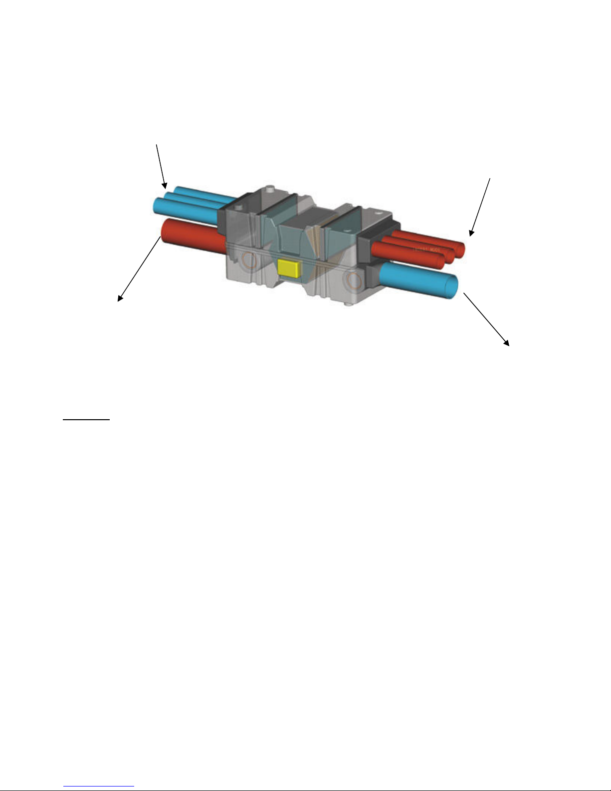
The ProAir system in your house is the PA 600 model shown in fig.1 It is designed to
operate 24 hours / day, 7 days/week, running at a low speed while the house is
normally occupied. At other times when there is higher than normal water vapour
generated (cooking & showers) the system can be triggered, extract higher volumes of
air, for a pre-defined period.
3
These two modes (low and occasional boost) will provide you with the regulation airchanges required for you and your dwelling. The medium mode is available for special
situations such as spring cleaning, or when extra people are in the house.
Fresh from outside@ 2°C RH 81%
Extract from
bathrooms & kitchen @ 20°C RH 66%
Exhaust to outside
@ 3°C RH 74%
Supply to bedrooms & living areas @18.5°C
Figure 1
When air is heated the relative humidity of the air reduces as shown above. This
allows water to be picked up and expelled to outside in one of two ways.
1. Exhausted directly with the stale air as water vapour.
2. Condenses in the heat exchanger exhaust passages and drains to outside via a
15mm hose connected from the bottom of the HRV unit to outside.
RH 36%
4
Figure
2
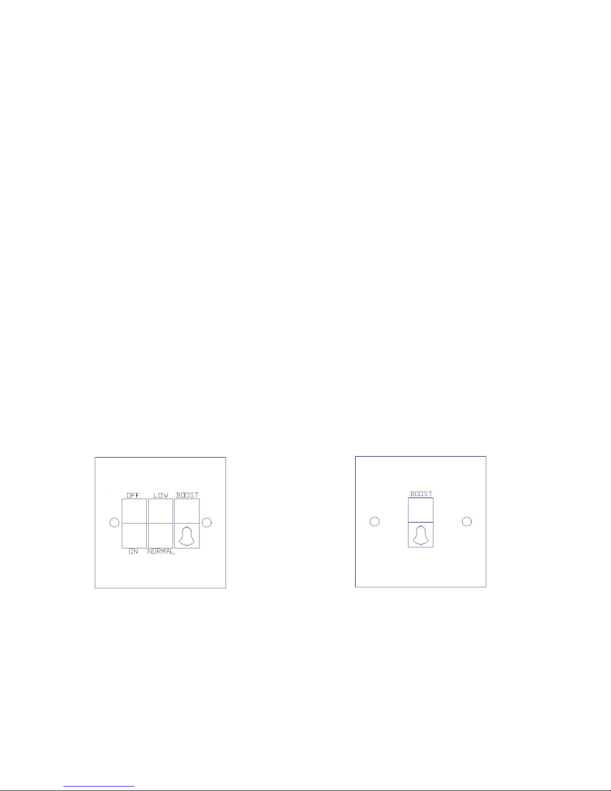
Control
In the utility room, or at some central point in the house you will find a switch as
shown below in Figure 2. This is the master controller. The system is controlled by
progressive switching. The options for controlling the unit are as follows:
Off: As with any other electro-mechanical system it can be switched off as
required, but it is recommended to run the system as much as possible.
On: In this position the other two switches are functional
Low Speed: Operate during normal occupancy at this position.
Medium Speed: Operate in this position during abnormal occupancy as described
above.
Boost Speed: Momentary depression of this switch provides a pre-set timed boost
for high water vapour generation (Cooking & showers). It is normal
that this switch does not stay on. The default pre-set time is 24
minutes, but this can be set to any time you like by the ProAir
technician.
While the system is in the boost mode, the low/normal switch is non-
operational.
The system goes back to the low or medium mode after the pre-set
time has elapsed.
At other locations throughout the house you will find switches as shown in Figure 3.
These are mimics of the boost switch on the main controller and allow you to go to
boost mode from outside your shower.
Pressing more than one boost switch together does not cause a problem. Whoever gets
there first triggers the timer.
5
Figure 3

Installation
The system consists of
• Air Handling Unit (AHU) unit usually located in the attic
• Intake and exhaust vents leading to outside
• Ducting to facilitate the transport of air to and from this unit to the various rooms
• Ceiling terminals for the delivery and extraction of air in rooms
• Control switches
The Air Handling Unit (AHU) is located in either the attic or a utility area. It contains
a high efficiency counter-flow heat exchanger, fans to drive air in and out and filters to
clean the air. It is mains powered (220V) from a standard 13Amp socket. It is
suspended by light chain from the rafters and supported slightly proud of the ceiling
joists. This is for two reasons, (a) to prevent any vibration and (b) to allow house
insulation under the unit.
The outer casing is made of polypropylene and is insulated on the inside where
possible to minimise noise levels and heat loss. It is just off level. This helps the egress
of water through the condensate drain. This is a 15mm plastic hose from the unit to the
outside. It has been provided to assist in the disposal of any water that may result from
condensation.
One end of the unit is connected to outside in order to take in fresh air and exhaust
stale air. There are a few options for this:
1. Duct connections to slate vents.
2. Duct connections to soffits
3. Duct connections to gables
4. A combination of any of above
The outdoor and intake vents have been reasonably separated to ensure that the
exhaust air is not collected as fresh air.
6
 Loading...