

Page 1
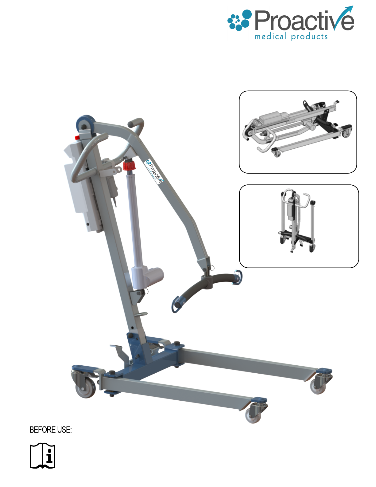
PROTEKT® TAKE-A-LONG
FOLDING ELECTRIC PATIENT LIFT
Model: 33400P
Folding Position #1
Folding Position #2 - Standing
- Flat
Ensure the product has been assembled according to the instructions in this
manual. All operators should read and understand the instructions for safe
and proper operation of the patient lift.
Page 2

Thank you for choosing !
To better serve you, please record
the following information for future use:
Supplier Name: ___________________________________________
Supplier Telephone: ________________________________________
Product Serial Number: _____________________________________
Date of Purchase: _________________________________________
1
Page 3
i
The allows the patient to be
lifted and transferred safely with minimal physical effort
provided by the operator. This is due to it being a full electric
lift . With the
Product Description
The uses a two point spreader bar. As
an added feature
away for people with limited space in the home or in the trunk
of your car for individuals who like to travel. With the addition
of the optional battery pack you will never have to be worried
about your lift not being charged and ready for use.
i
The
completely immobile or totally dependent on the patient lift for
transfers. The
space in the home or for customers who like to travel as it folds
Intended Use
is intended to be used with patients who are
this lift is able to be folded and stored
is intended for patients with limited
to be used for transfers of the patient in and out of bed, their
wheelchair, to and from the commode, or any other type of
surface. The
caregiver who will perform the lift and transfer. Transfers
should
used in high humidity environments for extended
amounts of time.
is intended to be operated by one
2
Page 4
DEFINITIONS & SYMBOLS
In this manual the user refers to the patient or resident and may be used
interchangeably at different times. Caregiver refers to the operator or person who is
assisting with the transfer.
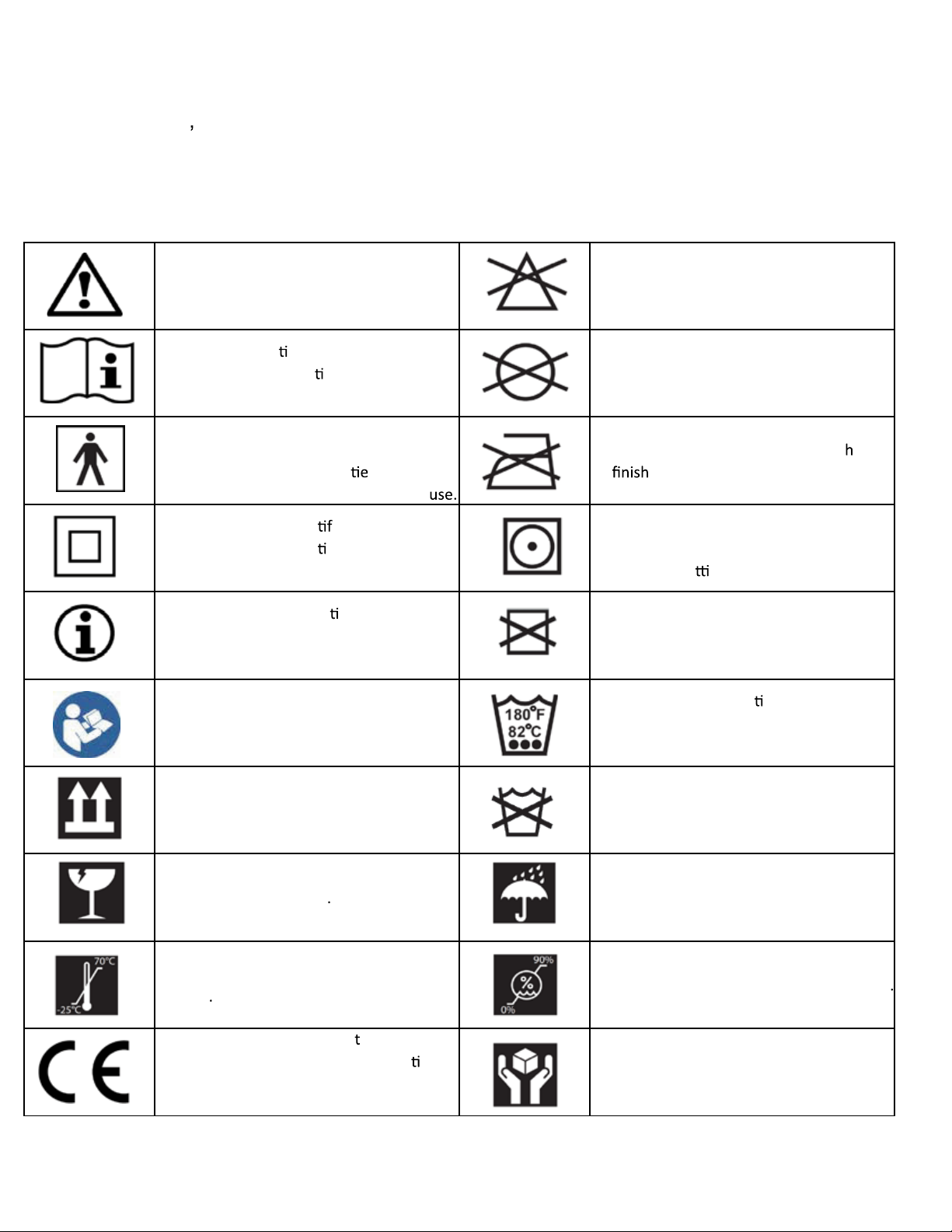
Symbols used in this manual and on the product and their meanings:
Warning! Failure to heed this warning may
result in damage to the product or serious
injury to the operator and/or user.
Important instruc
understand the instruc
before using the product.
Type BF applied part. Refer to the part of
the medical device which come into
physical contact with the pa
for the device to carry out its intended
Class II symbol. To iden y equipment is
designed that a connec
earth (ground) is not required.
Note! Important informa
the product and/or its correct and proper
usage follows.
Advise the operator to consult the
accompanying documents before use.
ons follow. Read and
ons in the manual
nt in order
on to electrical
on concerning
Do Not Bleach. No bleach product may be
used. The garment is not colorfast or
structurally able to withstand any bleach.
Do Not Dryclean. Garment may not be
commercially drycleaned.
Do Not Iron. Item may not be smoot ed
or
Tumble Dry, Normal, Low Heat. A machine
dryer may be regularly used at a maximum
of Low Heat se
Do Not Dry. A machine dryer may not be
used.
Machine Wash, Hot. Ini
temperature should not exceed 82°C or
180°F.
ed with an iron.
ng.
al water
Right side up Do Not Wash
Fragile, handle with care Keep dry
Carton storage temperature limit of -25°C
to 70°C
European Conformity mark, he product
conforms to European Medical Direc
93/42/EEC and meets applicable health,
safety and environmental requirements.
ve
Carton storage humidity limit of 0% to 90%
Handle with care
3
Page 5

i
A will provide years of service if it is properly
maintained as any electric and/or mechanical equipment requires.
Please pay careful attention to the following important information
regarding the care, maintenance, and operation of the patient lift.
Carefully read these instructions before assembling the lift, or
attempting to lift a user with the device.
• Before attempting to lift any patient, please practice operating the lift
and explain the lift procedures to the patient
• Please provide special assistance under the caretakers’ discretion.
(i.e. patients who are comatose, spastic, agitated, or otherwise
severely handicapped)
Safety Instructions
• The patient lift should be used solely for transferring a user/patient
from one utility (beds, chairs, toilets, etc.) to another. The patient lift
should not be used for transporting or moving any patient from one
location to another location.
• During lifting or lowering, whenever possible, always keep the base
of the lift in the widest position.
• The base of the lift should be closed before moving the lift.
• Do not roll casters over any object while the user/patient is in the
sling.
• Do not lock casters during lifting.
• While being lifted in a sling, always keep the user/patient centered
over the base and facing the caregiver operating the lifter.
• Never leave the user/patient unattended during lifting.
4
Page 6

WARNING!
• NO
equipment from its original state. This product is deemed safe to use with
equipment may result in serious injury or death.
• DO NOT replace any components of the lift without consulting with
, and follow proper instruction from when
replacing any components.
• DO NOT service any parts of the lift while in use with a patient.
• It is NOT safe to load the equipment more than the indicated maximum safe
working load.
• IF any accessories with lower load capacity than the equipment itself is used,
DO NOT load the equipment more than the lowest maximum safe
working load.
• REMOVE the battery pack if the lift will not be used for some time, to prevent
battery leakage. PERIODICALLY check the battery pack and the charger
• This equipment DOES NOT consist of any materials or ingredients to which
patients are exposed, that may cause bodily harm or injury.
• Prolonged exposure or physical contact with any part of the equipment WILL
NOT cause skin irritation, allergic reaction, etc.
• Using accessories, detachable parts, or materials not described in the
instruction manual MAY RESULT IN SERIOUS INJURIES.
• Keep the equipment away from children and pets when in use. IT MAY
CAUSE SERIOUS INJURY OR DEATH.
• Keep the equipment away from any pests or pest infested area. Diseases
transferred from pests to the equipment MAY CAUSE SERIOUS ILLNESS to
patients upon contact.
• If the lift is exposed to the sun for long periods of time, be CAUTIOUS as the
surface of the lift may be hot.
• There are no risk if the lift is exposed to reasonably foreseeable
environmental conditions
• CAUTION! The controller contains parts and assemblies that could be
susceptible to damage by electrostatic discharge (ESD). To reduce
the likelihood of this, one should be grounded prior to using the controller.
• DO NOT use the lift on a inclined surface that is greater than 5°.
• CAUTION! The black plastic bolt caps can fall off the bolt and is a choking
hazard. If the cap will not stay on the bolt, replace it immediately.
5
Page 7
FEATURES & OVERVIEW
7.6 lb
(3.5 kg)
0.7 lb
(0.3 kg)
0.6 lb
(0.3 kg)
11 lb
(5 kg)
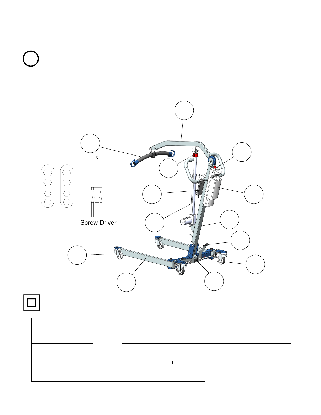
• Prior to assembly, unpack and inspect all parts from the shipping carton.
i
Contact your dealer immediately if any parts are damaged or missing.
• Easy tools are provided to assist with initial set up. To ensure maximum
safety, product should not be put into use until all connections are tightened
using standard tools.
1
2
9
13
10
Easy Tools
Screw Driver
12
11
3
4
6
7
5
Class II Equipment
1 Spreader Bar 6 Front Caster 11 Actuator
2 Boom 7 Rear Caster 12 Hand Control
3 Mast 8 Standing Bracket 13 Emergency Lowering
4 Leg Opening Pedal 9 Emergency Stop Bu
Combined
Weight (1-5)
67.2lb
(30.5 kg)
on Charger
8
5 **Base 10 Control Unit
** Heaviest detachable part
6
Page 8
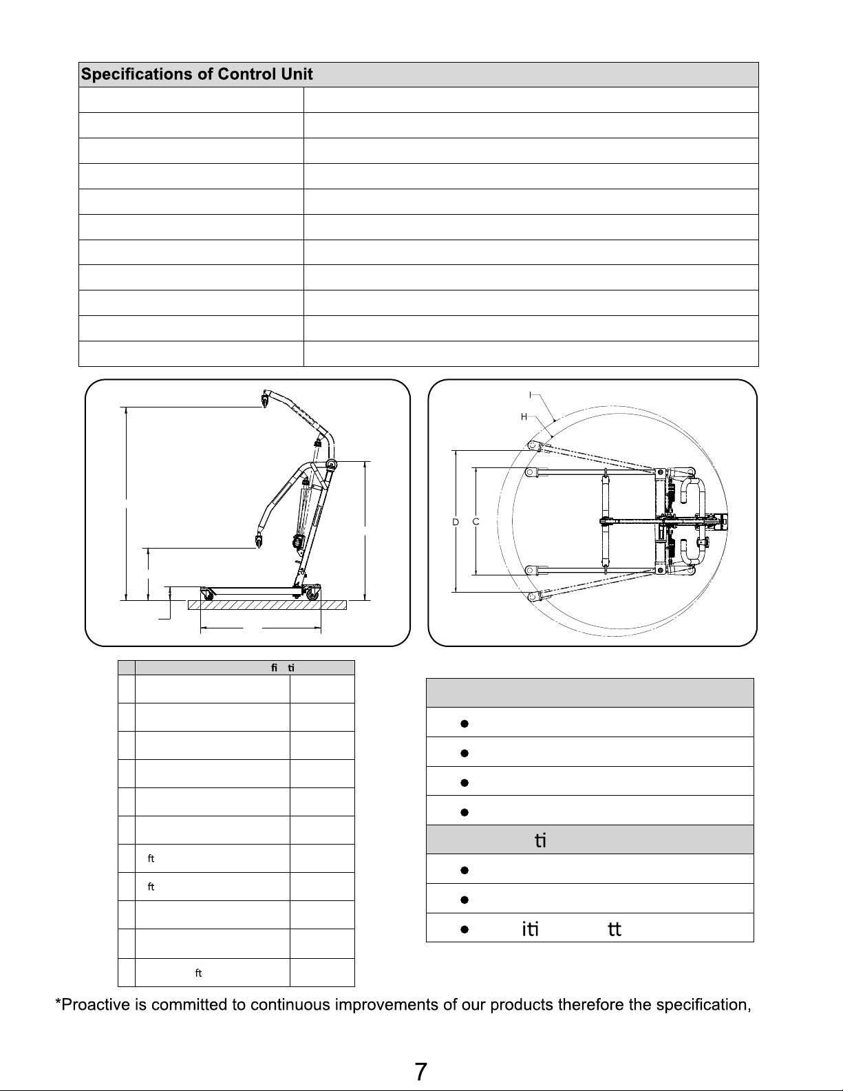
SPECIFICATIONS & OPTIONS
DESCRIPTION
DATE
APPROVED
Dimensions & Speci ca ons
400 lb
182 kg
41.0”
1041mm
25.6”
650mm
32.0”
813mm
48.3”
1227mm
4.7”
119mm
18.5”
465mm
67.2”
1707mm
55”
1384.9mm
51”
87.3 lb
39.7 kg
Standard Features
2-Point Spreader Bar
4” Rear Caster with Brake
3” Front Caster
Power Control Unit
Op onal Features
Charging Cradle
Digital Scale
Add onal Ba ery Pack
Input Voltage 220-240VAC 50Hz / 110-120VAC 60Hz
Output Voltage 24 VDC
Battery Pack 24 VDC 5AH
Lift Control Handset and Panel
Protection Class IP54 (Protection against dust and splash of water)
Sound Level Under Full Load 16db
Sound Level Under No Load 11db
Lift Cycles Per Charge 25 full cycles under full load
Overload Warning by LCD
Battery Status by LCD
Duty Cycle 10% Duty cycle (Max 2 minute ON,18 minute OFF)
H
G
F
A Safe Working Load
B Base Length
C Base External Width – Closed
D Base Internal Width – Opened
E Mast Height
F Front Caster Height
G Li ing Height – Lowest
H Li ing Height – Highest
E
B
dimensions, and features listed above are for guidance only and are subject to change without prior
notice.
I Base Opened Turning Diameter
H Base Closed Turning Diameter
Unloaded Li Weight
1306.5mm
Page 9
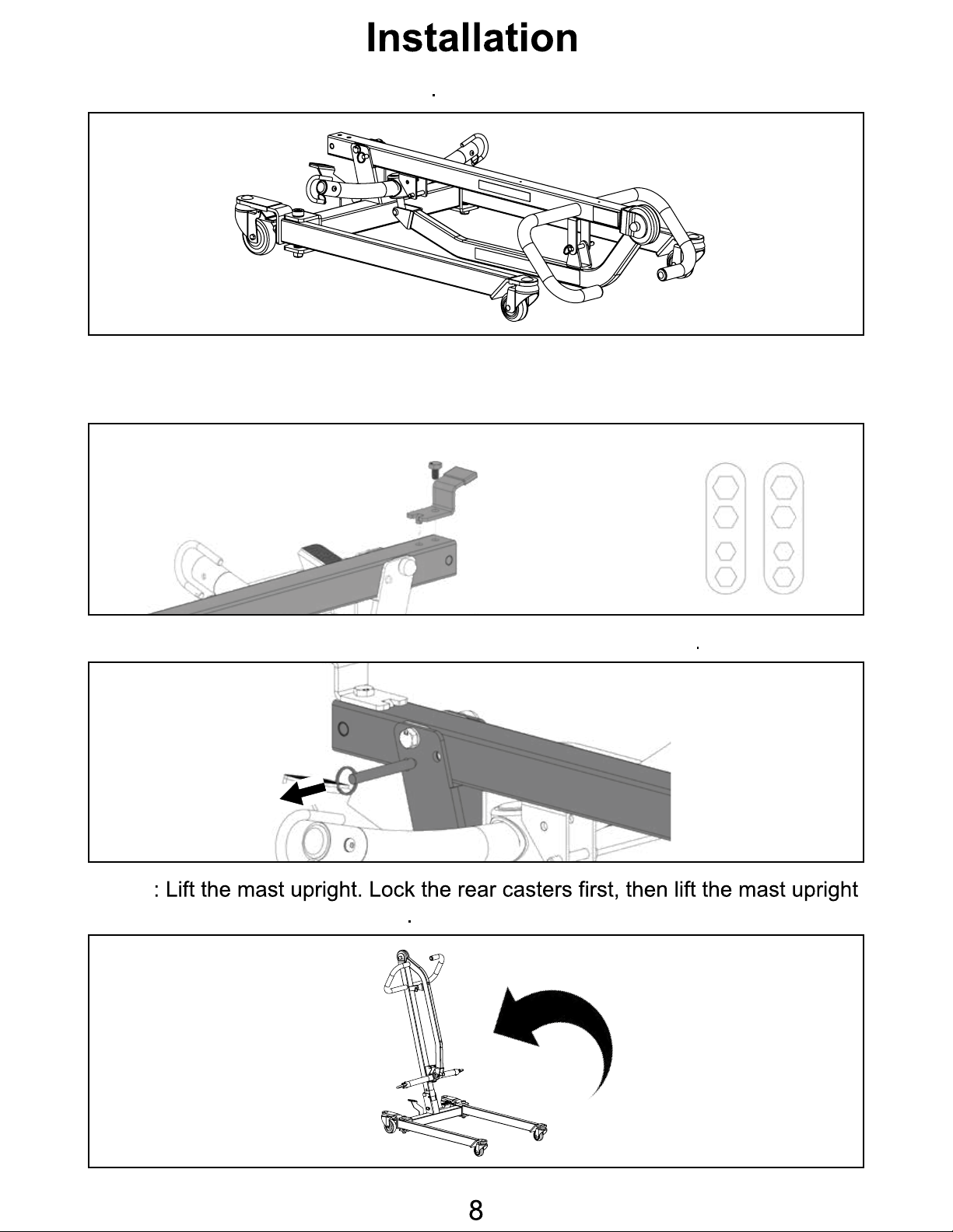
Step 1: Remove folded lift from box
Step 2: Secure the stand to the mast. Make sure the tab on the standing bracket
sit in the top hole on the mast, and insert the screw to the lower hole as follows.
Use the EZ-Tools to tighten the screws.
Step 3: Remove the quick release pin that is securing the mast
Step 4
by grabbing onto the handle bars
Page 10
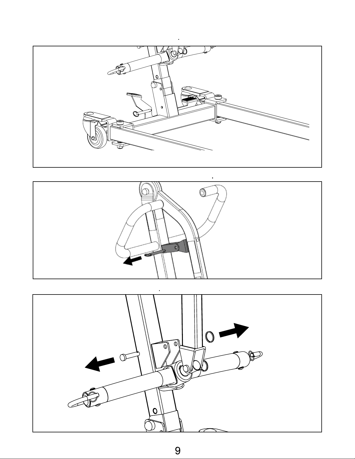
Step 5: Insert the pin to secure the mast
Step 6: Remove the pin that is securing the boom
Step 7: Remove lower actuator pin
Page 11
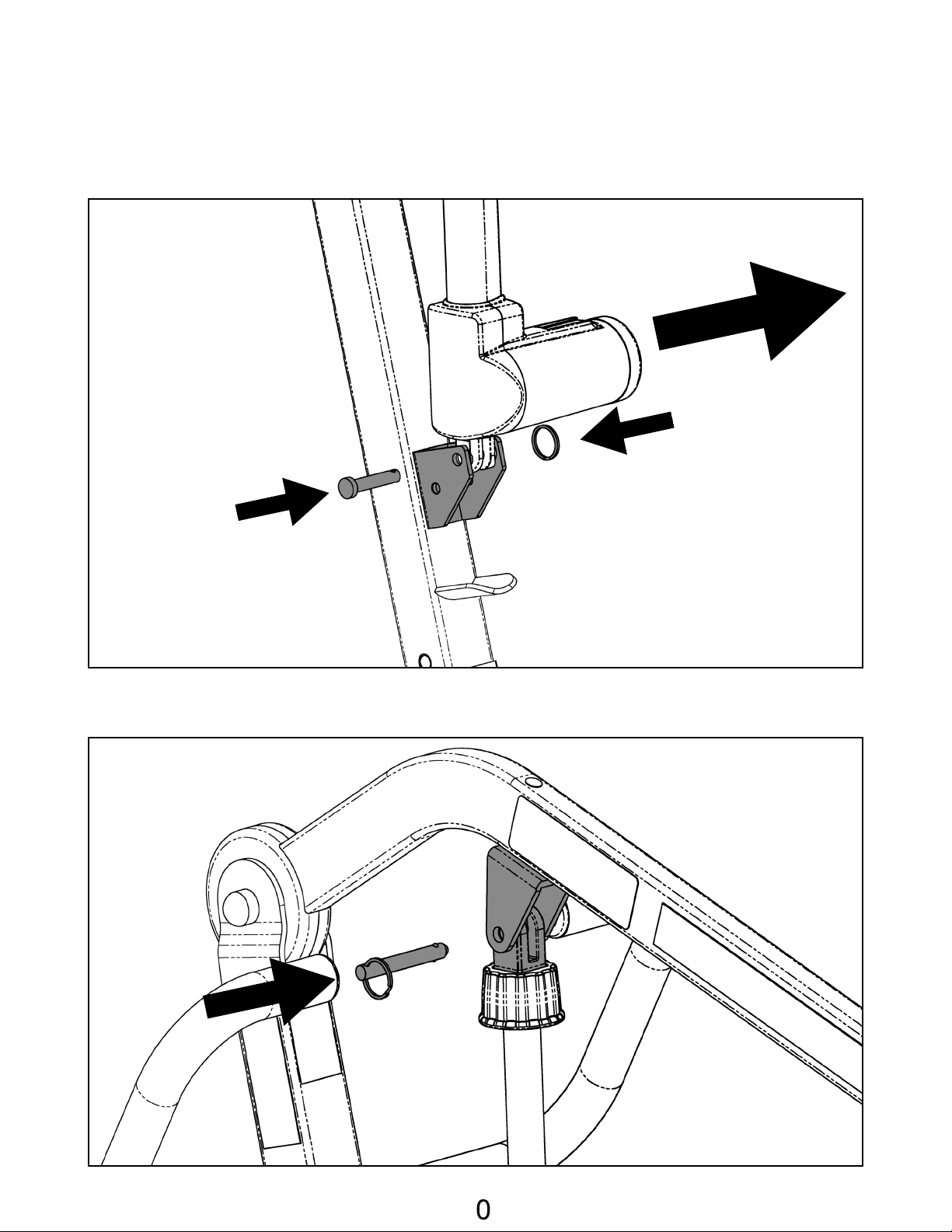
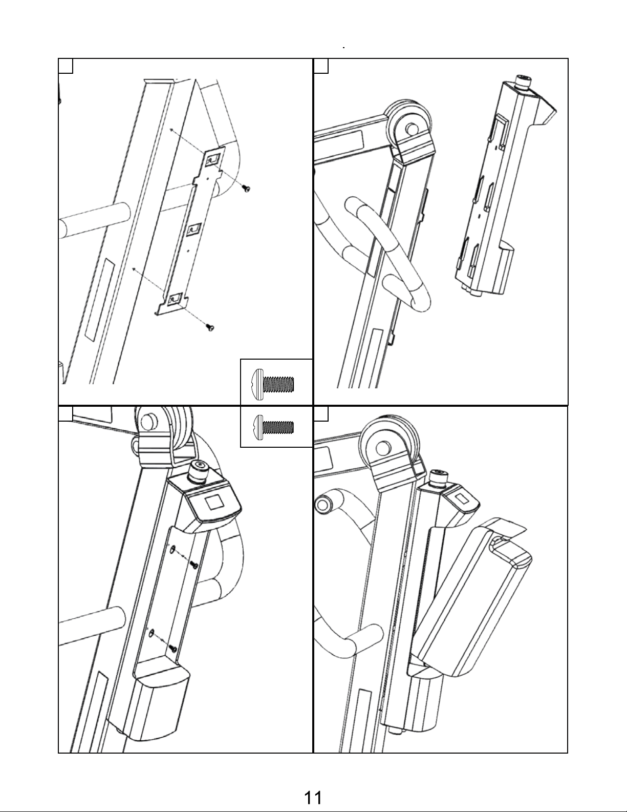
Step 8: Move the boom out of the way, and install the lower end of the
actuator as follows. It is critical to have the motor part of the actuator to face
the same direction as the big arrow as follows.
Step 9: Install the upper end of actuator and reinsert the quick release pin to
secure it.
1
Page 12
M5 SCREWS
UNLESS OTHERWISE SPECIFIED:
SHEET:
SCALE:
PART NUMBER:
DESCRIPTION:
DATE:
DRAWN BY:
MATERIAL:
FINISH:
2920 PACIFIC DRIVE
NORCROSS, GA 30071
PROPRIETARY AND CONFIDENTIAL
THE INFORMATION CONTAINED IN THIS
DRAWING IS THE SOLE PROPERTY OF
BESTCARE LLC. ANY REPRODUCTION IN PART
OR AS A WHOLE WITHOUT THE WRITTEN
PERMISSION OF BESTCARE LLC IS PROHIBITED.
9/27/2017
1 of 1
M4x0.7x10mm Machine Screw
ALL DIMENSIONS IN MM
1-6
6-30
30-120
120-400
0.1
0.2
0.3
0.5
Step 10: Installing the Control box on the Lift
1 2
3 4
M4 SCREWS
Page 13
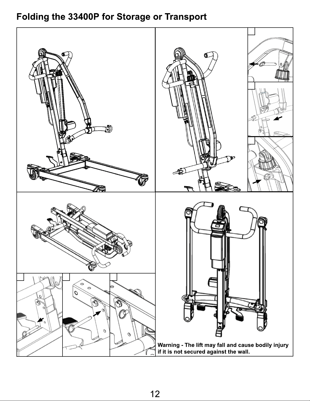
Step 1: Spreader bar at lowest position Step 2: Folding the boom
1
2
3
Step 3: Folding the mast
1
2
Step 4: Standing position
3
Page 14
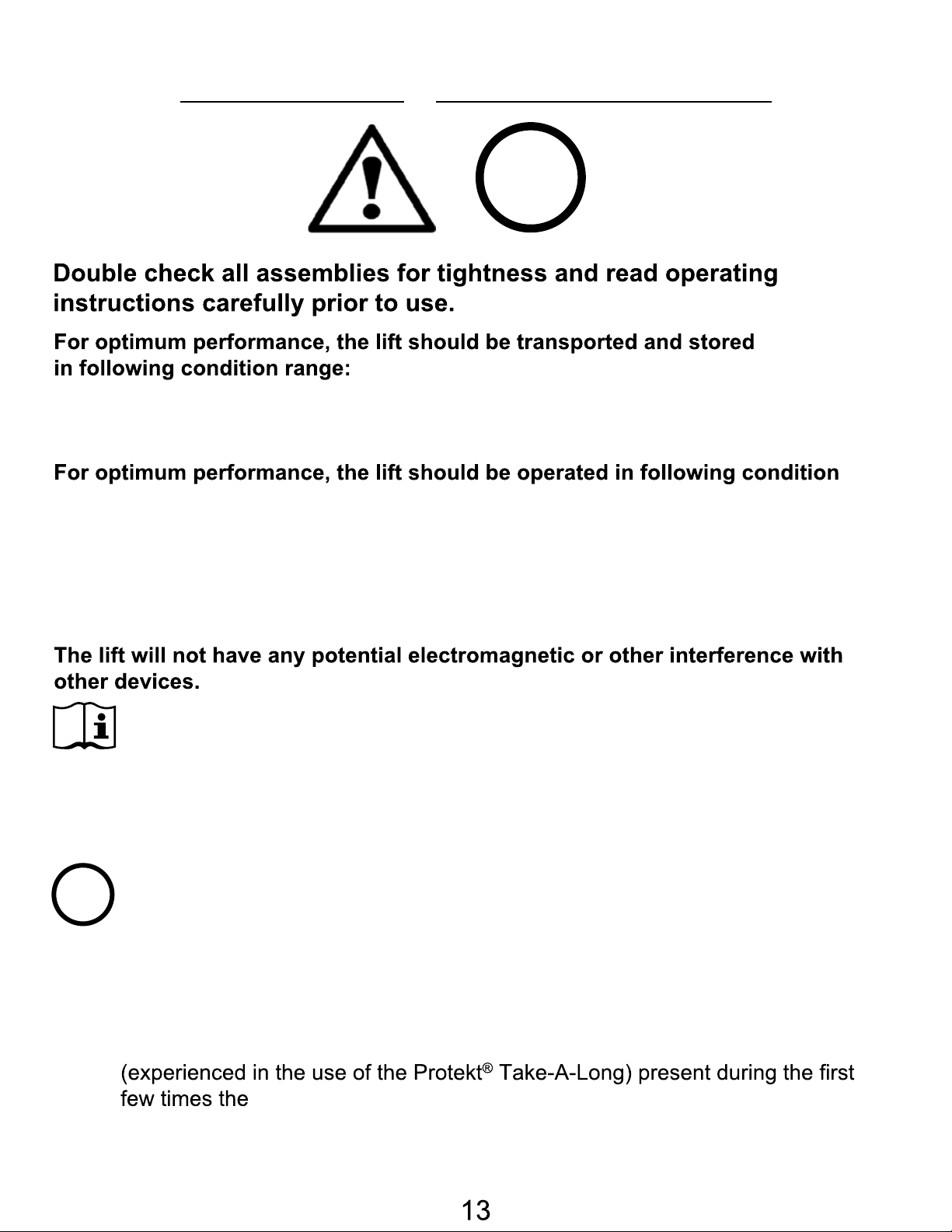
Operating Instructions
i
• -25°C to +5°C (-13°F to 41°F), and
• +5°C to +35°C (41°F to 95°F) at a non-condensing relative humidity 0% to 90%
• +35°C to +70°C at a water vapor pressure up to 5 kPa
range:
• at a temperature range of +5°C to +40°C (+41°F to +104°F)
• at a non-condensing relative humidity range of 15 % to 90 %, but not requiring a
water vapor partial pressure greater than 5 kPa
• 70 kPa to 106 kPa atmospheric pressure
i
PREPARATION BEFORE LIFTING
• Twist the RED EMERGENCY STOP BUTTON clockwise.
• Verify the Lifting and Lowering Functions by pressing either the UP or DOWN
button on the hand control once.
• Position the base of the lift around or under the object.
• Widen the base and disengage the caster brakes.
Do not attempt to transfer a patient without prior approval of the person’s nurse.
Also, do not transfer without having studied the instructions and performed
several practices in operating the product. Together (with the patients doctor,
nurse, or medical attendant) select a sling that is both practical and comfortable.
The sling selected should be one that serves the needs of the patient, while
providing the patient with optimal safety. Never interfere with the lift, unless
instructed by the attendant. Have a doctor, nurse, or medical attendant
lift is used to transfer a new user.
Page 15
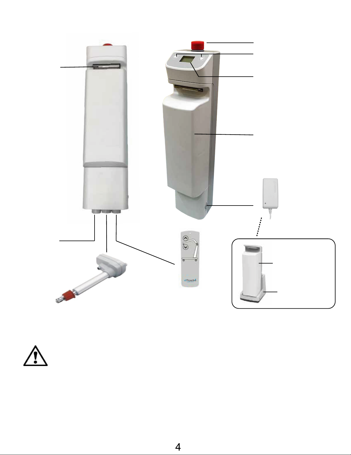
Battery Pack
Release Handle
Power Control Unit Overview
Emergency Stop Button
Up / Down Button
LCD Display Panel
Battery Pack
Charger
DC In
Not Used
Actuator
Hand Control
1. Connect Actuator as shown above.
2. Connect Hand Control as shown above.
3. The battery should be charged daily to prolong the battery life.
WARNING!
Additional Battery Pack
(Optional)
Charging Cradle
(Optional)
• Contains a long charger cord that may cause strangulation if used improperly!
• Keep long charger cord out of walkway where it poses a
tripping hazard!
• Have the charger port on the controller facing away from the wall for easy
disconnection!
• When removing the battery, need to secure the battery with both hands as it
can cause injury if dropped!
1
Page 16
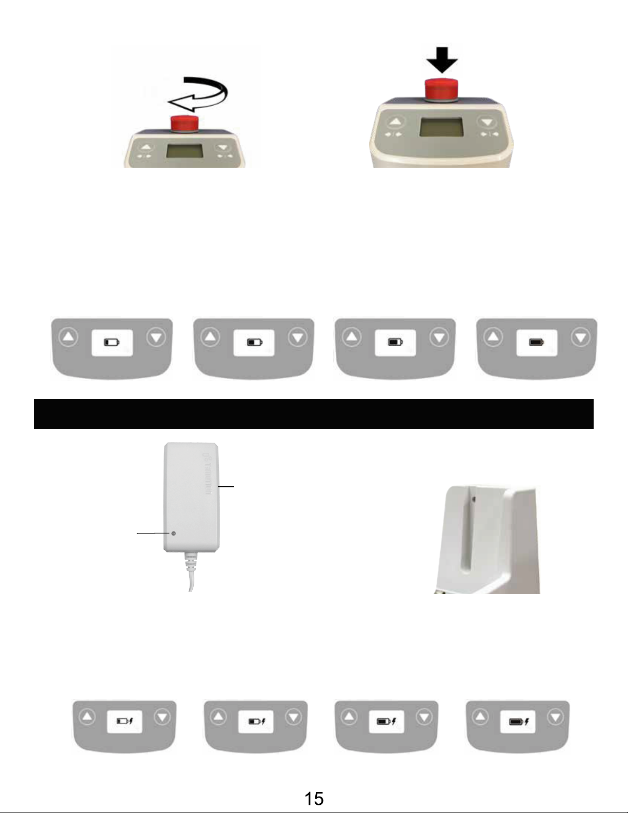
Release
Pressed In
LCD Display Panel Signs
When the emergency stop button is released, the LCD Display Panel will show one of the four signs
below.
• The sign will display for 5 seconds.
• Then the lift will go into standby mode and the sign disappears.
• The lift is ready for use.
Charging: DC Charger or Charging Cradle
Charging Cradle (Optional)
DC Charger
(included)
LED Indicator
* Amber = charging
* Green = charging completed
LCD Display Panel Signs - Charging
During charging, the LCD Display Panel will show one of the four signs below.
• The DC Charger must be connected.
• The emergency stop button must be released.
• The battery will not be charged if the emergency button is pressed in.
Page 17
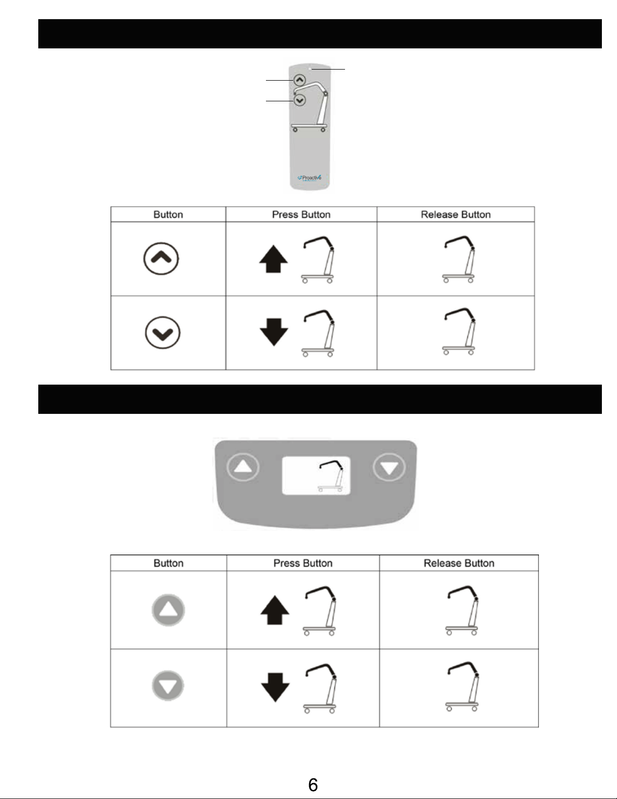
Operating Lift: Using Hand Control
Lifting
Lowering
LED Indicator
* Green = In Use
* Blank = Standby
Operating Lift: Using LCD Display Panel
1
Page 18
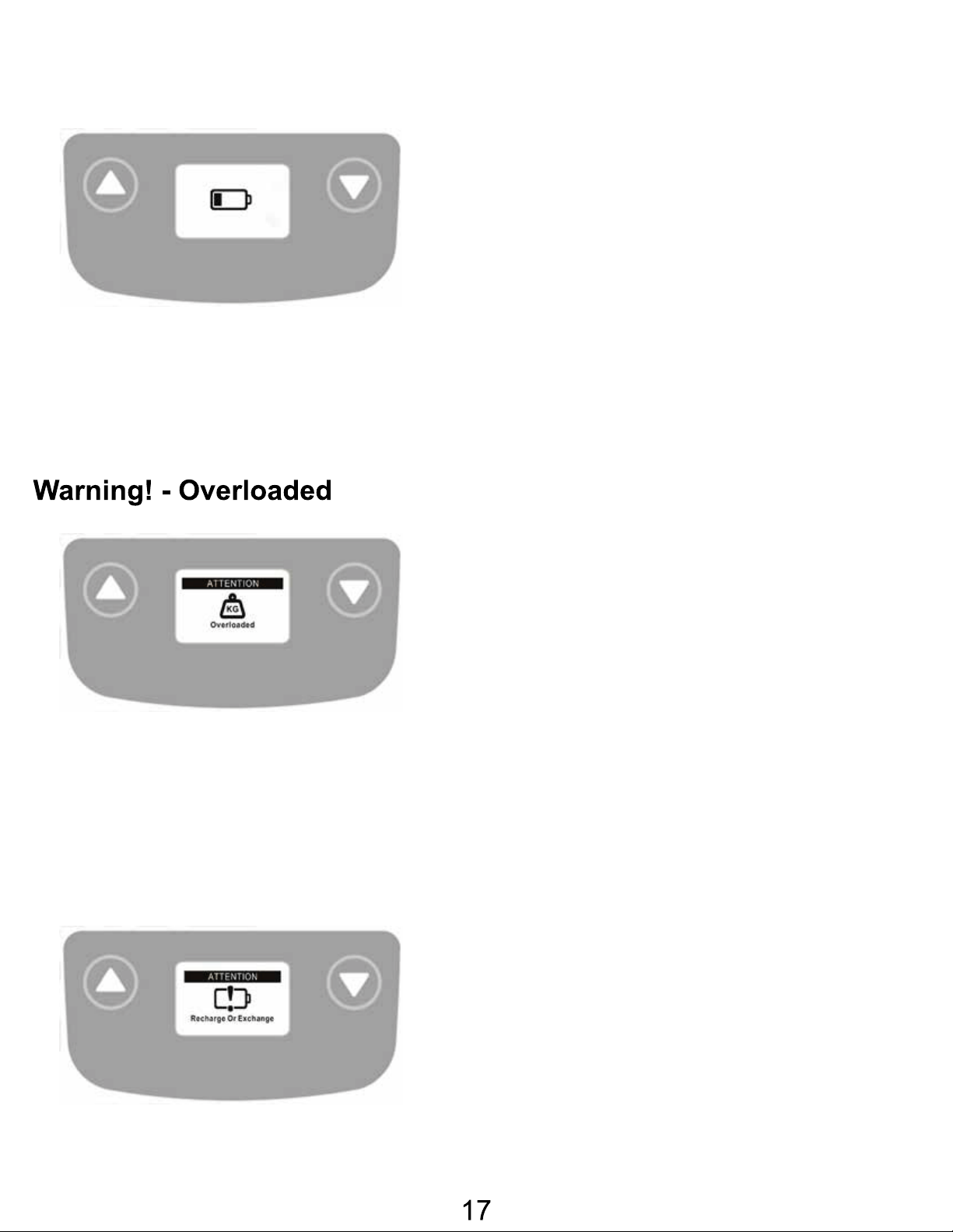
Warning! - Battery Low and Charging is Needed
If the battery needs to be charged, the LCD
Display Panel will show a blinking low battery sign
shown on the left either when the emergency stop
button is released or when a button on the LCD
Display Panel is pressed.
• Lift is still functioning.
• Buzzer will beep every 2 seconds.
• Battery needs to be charged immediately after
use.
During lifting if the lift is overloaded, the LCD
Display Panel will show the sign on the left and
lifting will be deactivated immediately.
• The buzzer will beep 3 times.
• Lowering the lift by pressing the DOWN
button is still allowed.
• The emergency stop button must be pressed
in and then release the button before further
lifting.
Warning! - Charge Battery Immediately
If the battery is critically low, the LCD Display
Panel will show the sign on the left either when
the emergency stop button is released or when a
button on the LCD Display Panel is pressed.
• Lift operation is deactivated.
• Battery needs to be charged immediately
before further use.
Page 19
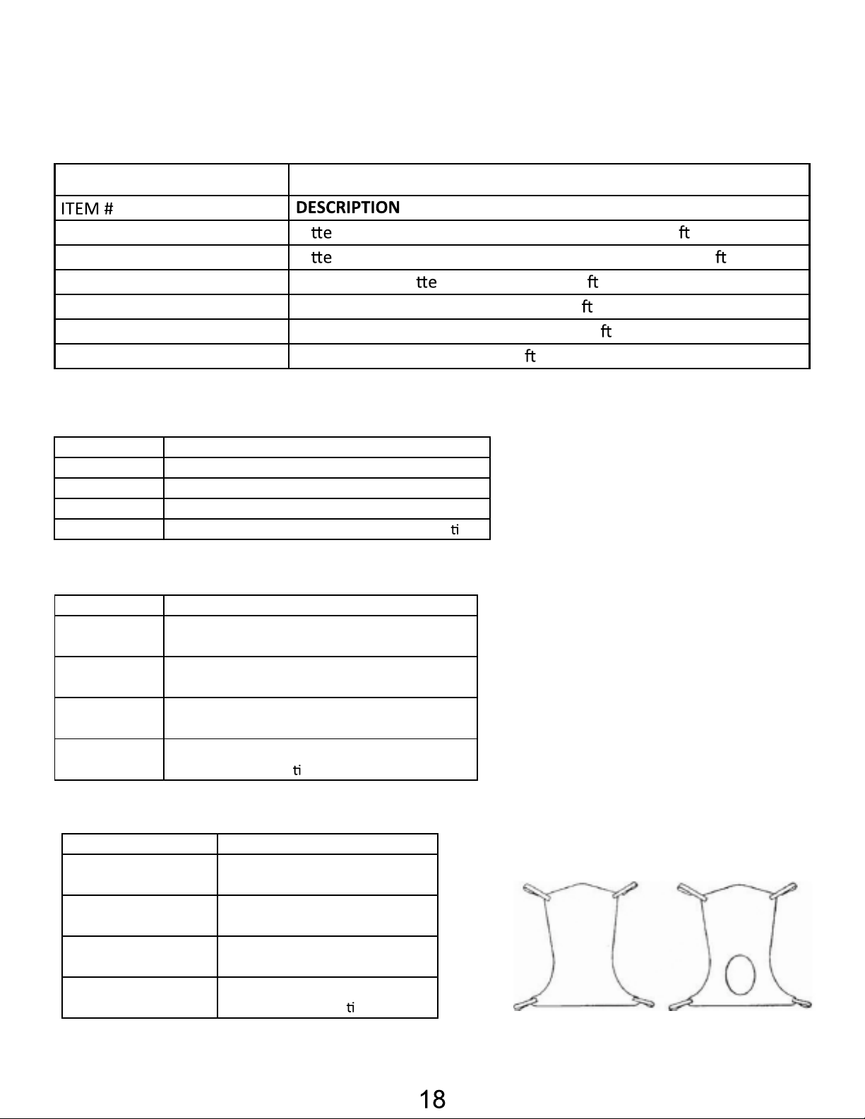
REPLACEMENT PARTS
LP-TBC2-CRDL Ba ry Charger Cradle ONLY (no plug) f/ Protekt Li /Stand
LP-TBC2-CRDL-PK Ba ry Charger Cradle Pack (includes plug) f/ Protekt Li /Stand
LP-TC12-BPAK Replacement Ba ry Pack f/ Protekt Li /Stand
LP-TC12-CBOX Replacement Control Box f/ Protekt Li /Stand
LP-TH10-PEN Replacement Hand Pendant f/ Protekt Li /Stand
LP-TP7C-ADP Replacement Plug f/ Protekt Li /Stand
Use ONLY Proactive Medical slings/products with this
ITEM # DESCRIPTION
30110 Medium
Mesh full body: medium 600 lb. weight capacity
30111 Large
Mesh full body: large 600lb. weight capacity
30124 X-Large
Mesh full body: X-large 600lb. weight capacity
30118 XX-Large
Mesh full body: XX-large 600lb. weight capac
y
ITEM # DESCRIPTION
Mesh full body: medium w/ commode opening
600 lb. weight capacity
Mesh full body: large w/ commode opening
600lb. weight capacity
Mesh full body: X-large w/ commode opening
600lb. weight capacity
Mesh full body: XX-large w/ commode opening
600lb. weight capac
y
DESCRIPTION
Solid fabric full body: medium
600 lb. weight capacity
Solid fabric full body: large 600lb.
weight capacity
Solid fabric full body: X-large
600lb. weight capacity
Solid fabric full body: XX-large
600lb. weight capac y
ITEM #
Full Body Mesh Slings
Warning!
Full Body Mesh Slings w/Commode
30114 Medium
30115 Large
30116 X-Large
30119 XX-Large
Full Body Solid Slings
30112 Medium
30113 Large
30117 X-Large
30123 XX-Large
Page 20
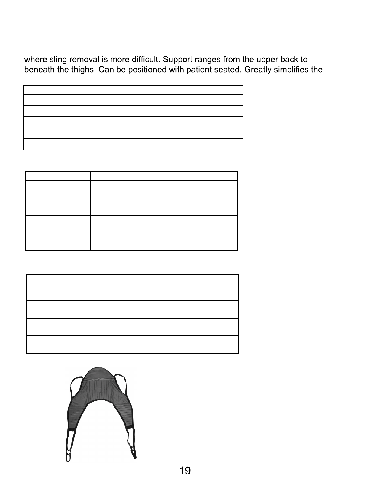
Divided Leg Slings
DESCRIPTION
Solid divided leg: small 450 lb. weight capacity
Solid divided leg: medium 450 lb. weight capacity
Solid divided leg: large 450 lb. weight capacity
Solid divided leg: XX-large 600 lb. weight capacity
ITEM #
DESCRIPTION
Solid padded divided leg w/o head support: small
Solid padded divided leg w/o head support: medium
Solid padded divided leg w/o head support: large 600
Solid padded divided leg w/o head support: X-large
ITEM #
DESCRIPTION
Solid padded divided leg w/ head support: small 600
Solid padded divided leg w/ head support: medium
Solid padded divided leg w/ head support: large 600
Solid padded divided leg w/ head support: X-large
ITEM #
Divided leg design is best suited for high level spinal cord injuries or patients
use of bathroom facilities.
30100P Small
30100 Medium
30101 Large
30102 X-Large
30103 XX-Large
Solid divided leg: X-large 450 lb. weight capacity
Padded Divided Leg Slings w/o Head Support
30100P-NHS Small
30100-NHS Medium
30101-NHS Large
30102-NHS X-Large
600 lb. weight capacity
600 lb. weight capacity
lb. weight capacity
600 lb. weight capacity
Padded Divided Leg Slings w/Head Support
30100P-HS Small
lb. weight capacity
30100-HS Medium
30101-HS Large
30102-HS X-Large
600 lb. weight capacity
lb. weight capacity
600 lb. weight capacity
Page 21
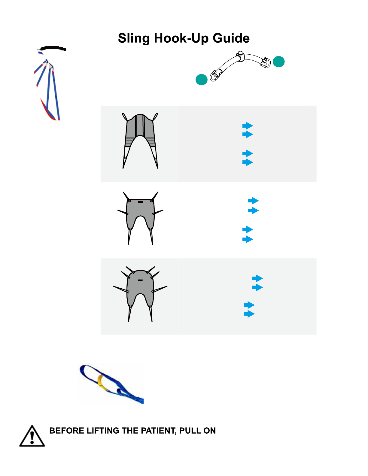
6 Point S-Bar
1
3
5
A B
Hook up A
Hook up B
Hook up D
Hook up C
Insert D through C
Hook up A
Hook up B
Hook up C
Hook up D
Hook up F
Hook up E
Insert F through E
Hook up A & C
Hook up B & D
Hook up E
Hook up F
Hook up H
Hook up G
Insert H through G
C D
4 Strap Sling
A B
1
2 Point S-Bar
Insert D through C
2
Point 1Hook up A
Point 2Hook up B
Point 1Hook up D
Point 2Hook up C
SAFETY LOOP
CENTER LOOP
SHORT LOOP
TO ENSURE THE LOOP IS HOOKED ONTO THE SPREADER BAR
PROPERLY.
C D
E F
6 Strap Sling
A B
C D
E
G H
8 Strap Sling
Sling Loop Options
Insert F through E
F
SAFETY LOOP - DO NOT USE FOR LIFTING
**safety loop is used with the center loop or short loop.
CENTER LOOP - reclined position
SHORT LOOP - upright position
Insert H through G
EACH SLING LOOPS
Point 1Hook up A, C
Point 2Hook up B, D
Point 1Hook up F
Point 2Hook up E
Point 1Hook up A, C, E
Point 2Hook up B, D, F
Point 1Hook up H
Point 2Hook up G
20
Page 22
2
4
Point 1
Point 2
Point 5
Point 6
Point 1
Point 2
Point 3
Point 4
Point 5
Point 6
Point 1
Point 2
Point 3
Point 4
Point 5
Point 6
2
4
Point 1
Point 2
Point 5
Point 6
Point 1
Point 2
Point 3
Point 4
Point 5
Point 6
Point 1
Point 2
Point 3
Point 4
Point 5
Point 6
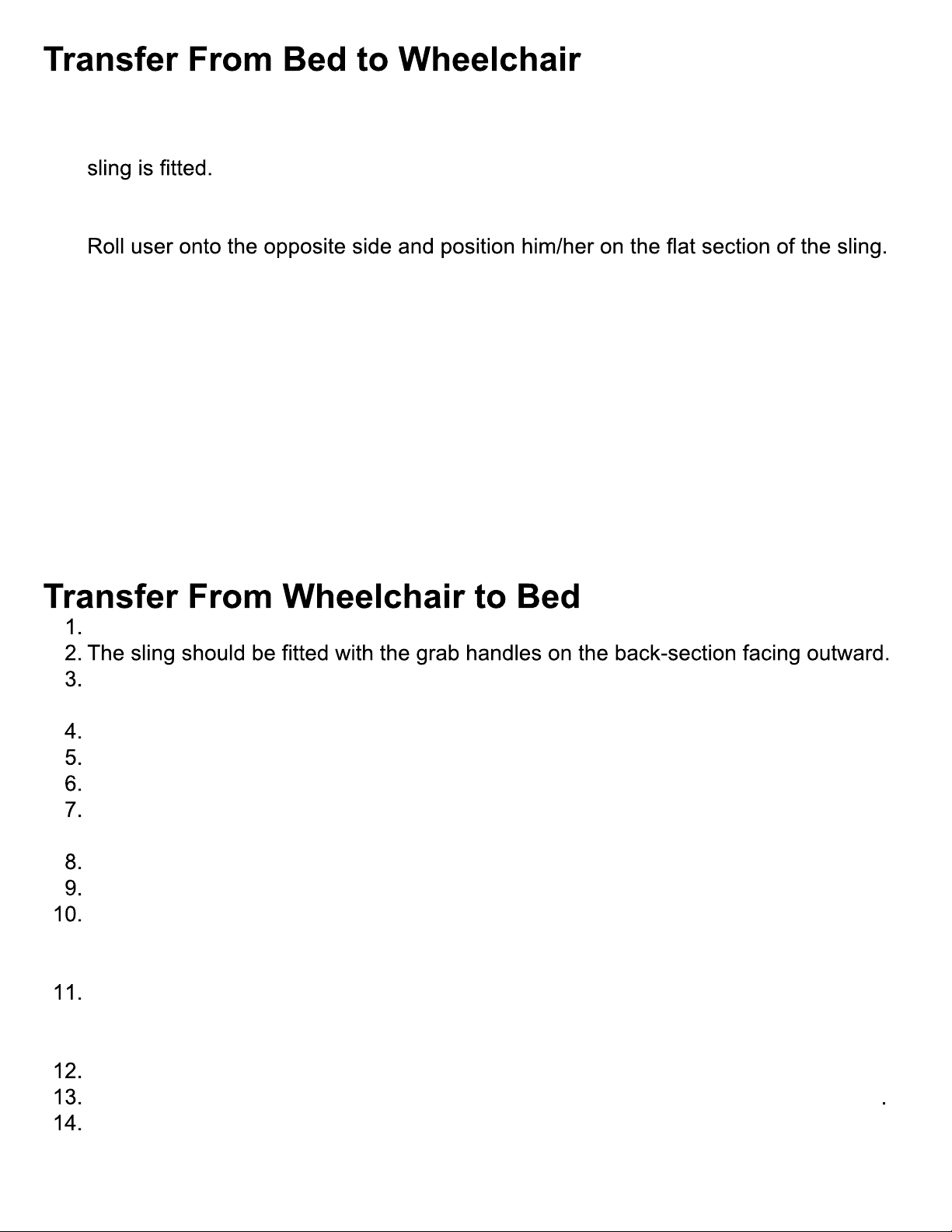
1. User/patient should be in the center of the bed.
2. Position user onto his/her side by rolling user towards you.
3. Roll the sling in half. The handle on the back section should face outward when the
4. Position the sling under the user/patient so the commode aperture aligns with the
base of the spine and top of the sling close to the neck.
5.
This will allow you to unroll the remainder of the sling from the other side of the user.
6. Once the sling has been positioned centrally, feed the leg sections under the thighs
and draw them up between the thighs.
7. Raise the head of the bed if this function is available.
8. Move the lift slowly towards the user and position the spreader bar over the user’s/
patient’s chest. Attach loops of the sling to the hooks on Spreader Bar as shown in
the Sling Hook-Up Guide.
9. Lift the user off the bed using the hand control.
10. Pull lift away from bed. Position user over the wheelchair or chair then lower the
patient onto the surface.
11. Reverse the above procedures when returning the user/patient to bed.
Grasp the sling at each corner of the “U” shape of the commode aperture.
Help the user lean forward slightly, then slide the sling down between the chair and
the user’s back.
Position the commode aperture where the buttocks meets the seat.
Position the sling equally around both sides of the body.
Draw the leg sections to the front along the length of the user’s thigh.
Check the sling’s central positioning by comparing the lengths of the leg sections
when they are drawn forward.
Reposition the sling if the leg sections are not equal in length.
Feed the leg sections under the thighs.
From between the legs, gently pull the leg section up the inner thigh. Feed as much
material as possible under and between the thighs. Ensure the leg sections are
positioned midway under the thighs to provide good support and greater comfort.
Move the lift slowly towards the user and position the spreader bar over the user’s
chest. Attach loops of the sling to the hooks on Spreader Bar as shown in the Sling
Hook-Up Guide.
Lift patient above the wheelchair by using the hand control.
Pull lift away from wheelchair. Position patient over bed and lower patient onto bed
Reverse the above procedures when returning the user/patient to a wheelchair.
21
Page 23
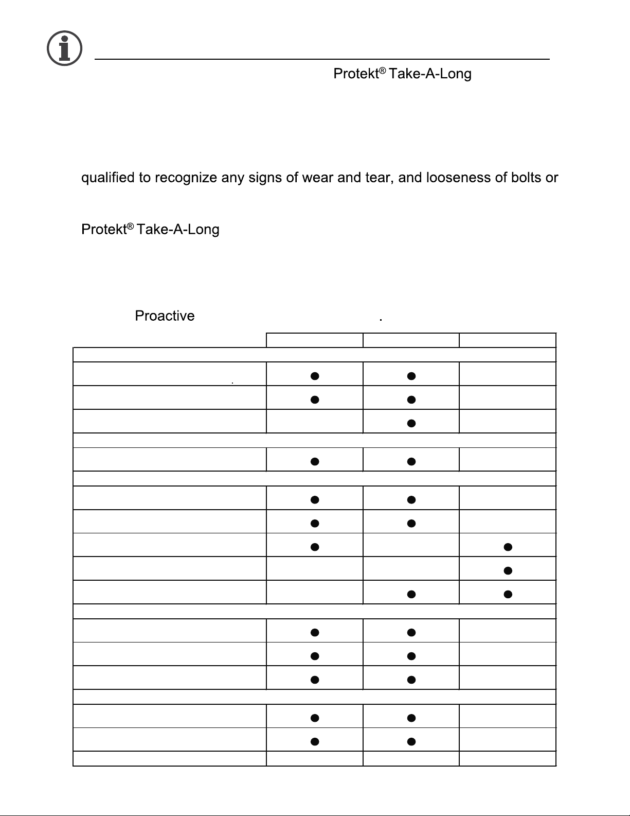
Maintenance & Inspection
First Received Monthly Every 3 Months
Check connections between boom and mast
for improper connection, looseness or wear.
Check rubber parts on the casters for
deflection.
Apply grease to caster ball bearings if
needed.
Make sure the control box is firmly affixed to
the mast.
Make sure the actuator is secured to the
boom and mast with pins and key rings.
Make sure actuator plug into control box is
not loose.
Lift Cleaning
As Needed. As Needed. As Needed.
Boom & Spreader Bar
Mast
Base & Foot Pedal
Actuator & Control Box
Sling & Sling Hardware
• The operator of the lift shall inspect the before each
use. Check all bolts for tightness. Make sure the base can be easily
widened, and that all lift parts are in place. Make sure that casters can be
turned freely, and that caster brakes can be engaged. Make certain all
necessary items (i.e. slings, and wheelchairs, etc.) are ready for use.
• At least once a month, the lift should be thoroughly inspected by a person
parts. Replace any worn parts immediately.
• To lubricate, put silicone lubricating grease on the following points when the
is placed into service and every month thereafter: Top
of Mast, Spreader Hinge, and Caster Axles.
• With proper use and care, the expected lifetime of the lift is 10 years or
20,000 cycles.
• The expected lifetime of the electrical components are 3 years.
• Contact for any recycling information
Check connections between boom and
spreader bar for improper connection
Check the boom for bending and deflection.
Check the mast for bending or deflection.
Check bolts and nuts for looseness.
Check casters and axle bolts for tightness.
Check welding joints for rust and crack.
Check sling for wear.
Check sling hardware every time before use.
22
Page 24
Cleaning and Disinfecting
• Use pH-neutral detergents only.
• Remove the battery from the controller
• Clean lift surfaces, control box and hand control with a damp cloth using pHneutral detergent.
• Remove debris and hair from the casters and make sure the casters can
spin and swivel freely.
• Solvents or strong liquids or abrasive cleaning products will damage the
surfaces of the lift.
• Check with sling label for washing condition.
• As for minor cleaning between patient uses, we recommend wipes with
water-soluble soap or isopropyl alcohol.
• For slings with rigid supports, remove the plastic inserts before washing. (Look
for an opening near the plastic inserts for removal)
• Machine wash warm or cold.
• Do not wash with other colors.
• Air dry or very low dryer heat.
• DO NOT USE BLEACH.
• DO NOT clean or wash disposable slings.
• REPLACE a sling when it show
• Contact for “Guideline for Identifying Deteriorated Slings” if
needed.
• Inspect slings prior to each use for contamination from previous use.
• Use isopropyl alcohol for any disinfection purpose.
signs of deterioration.
• Wash a reusable sling for serious contamination
• Replace a disposable sling for any contamination
• Reusing a contaminated sling can cause serious bacterial infection
23
Page 25

Troubleshooting Guide
The following list of encountered problems and solutions will assist you in determining
what may be causing your patient lift not to function as designed. If you have a problem
occurring which is not listed below please contact your dealer or technical support for help.
Do not attempt to repair or replace components or parts on your lift as this may void your
warranty or cause further problems that may result in patient injury. Stop using your lift
immediately if it is not functioning correctly or any warning beeps are heard.
I need to re-charge my batteries often or they fail to hold a charge when I charge
them
• Replace the batteries or battery pack as they are at the end of their life cycle
• Batteries should be changed every 18-24 months depending on usage
The actuator will either go up or down but not both
• Replace your hand control as it is at the end of its life cycle
• Your control box may be malfunctioning
There is a grinding sound inside the actuator when lifting
• Replace your actuator as the internal gears are stripped
The actuator stops and starts while lifting or lowering
• Replace the batteries or battery pack as they are at the end of their life cycle
My lift will not operate even though it shows the batteries are charged
• Unplug the AC power cord from the control box as the lift will not work when the
control box/charger is connected to AC Power.
• Check to make sure the hand control is properly inserted all the way into the control
box port.
• Check to make sure the actuator plug is properly connected and inserted all the way
into the control box
• Your hand control needs to be replaced as it is at the end of its life cycle
If there is a problem you could not solve, please contact your dealer for assistance.
24
Page 26
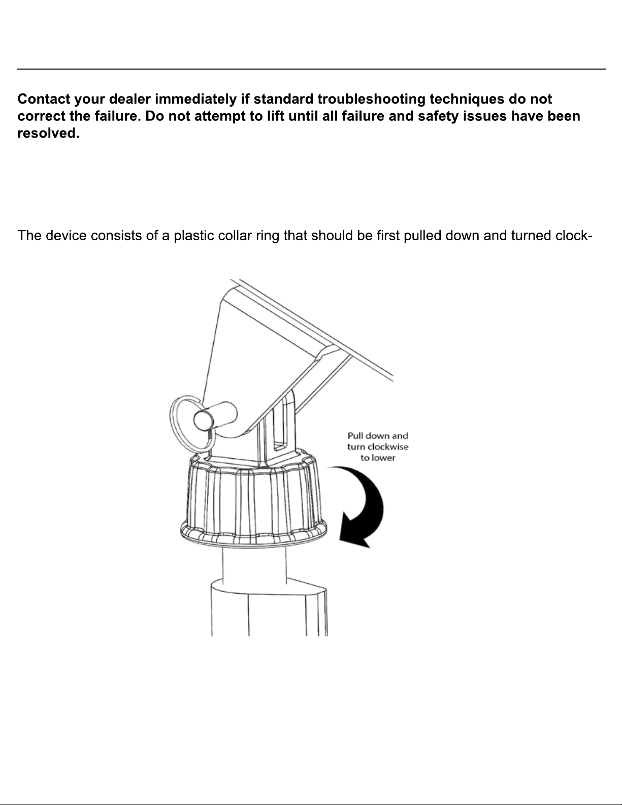
Emergency Lowering Mechanism
In case of lift failure, please follow the procedures below to safely lower the user.
The Emergency Lowering Device is located at the top of the actuator shaft. It is intended for
use if the actuator or electronics fail to operate while the patient is suspended in midair.
wise continually until the patient has been lowered.
NOTE:
THE EMERGENCY LOWERING DEVICE IS INTENDED FOR USE DURING LIFT
FAILURE. THIS DEVICE WILL ALLOW LOWERING OF PATIENTS ONLY. PLEASE
CONTACT YOUR DEALER IMMEDIATELY IN CASE OF FAILURE.
25
Page 27
WARRANTY POLICY
26
Page 28
. .com
 Loading...