

Page 1

Operating instructions SPEEDY F4 & F2
0
MOBILITY MADE SIMPLE!
Operating instructions
Service booklet
SPEEDY F4
SPEEDY F2
Page 2

Operating instructions SPEEDY F4 & F2
1
Contents
1Preface ............................................................................................................................................... 5
2Legend ................................................................................................................................................ 5
3CE Declaration of Conformity/other information ................................................................................. 5
3.1Classification ............................................................................................................................... 5
3.2Declaration of Conformity ........................................................................................................... 5
3.3Manufacturer ............................................................................................................................... 5
4Scope of delivery and testing the product on receipt ......................................................................... 5
5Introduction ......................................................................................................................................... 6
6Intended purpose ............................................................................................................................... 6
7Acceptable usage and operating conditions/places of use ................................................................ 6
8Technical specifications ..................................................................................................................... 7
8.1Product weight ............................................................................................................................ 7
8.2Load weight ................................................................................................................................ 7
8.3Obstacle height and turning circle .............................................................................................. 7
8.4Basic equipment & dimensions .................................................................................................. 7
8.5Service life .................................................................................................................................. 7
9Rating plate ........................................................................................................................................ 7
10Commissioning ................................................................................................................................... 7
11Hand-over ........................................................................................................................................... 8
12Getting to know the product ............................................................................................................... 8
13Safety instructions – prior to driving/use ............................................................................................ 8
14Safety instructions – while driving/using ............................................................................................ 9
15Safety instructions regarding obstacles ........................................................................................... 11
16Safety instructions regarding dangerous locations and dangerous situations ................................. 11
17Safety instructions – after driving/use .............................................................................................. 12
18
Individual setting options ......................................................................................................... 13
18.1Adjusting the seat height at the front by positioning the caster wheels in the caster wheel fork .
.................................................................................................................................................. 13
18.2Adjusting the seat height at the front by changing the caster wheel fork ................................. 13
19Back system ..................................................................................................................................... 14
19.1Backrest angle .......................................................................................................................... 14
19.1.1
Adjustment possibilities with backrests fixed by being bolted onto side panels 14
19.1.2Adjustment possibilities with an adjustable backrest ................................................. 15
19.1.3Instructions for sitting posture with an adjustable backrest ....................................... 15
19.1.4Adjusting the backrest angle or folding down the backrest with an adjustable backrest
...............................................................................................................................................15
Page 3

Operating instructions SPEEDY F4 & F2
2
19.2Adjustable back padding & their adjustment options ................................................................ 16
19.3Ergonomic back shell & its setting options ............................................................................... 19
19.4Ergo Back backrest bracket and its adjustment possibilities .................................................... 20
20Seat system ...................................................................................................................................... 21
21Clothing guard .................................................................................................................................. 22
21.1Side panel with integrated clothing guard ................................................................................. 22
21.2Side panel with bolt-on clothing guard ...................................................................................... 22
21.2.1Overview of terms ...................................................................................................... 22
21.2.2
Removal and attachment of the clothing guard ................................................. 22
21.2.3
Adjusting the clothing guard position ................................................................. 22
21.3Clothing guard removable via lock function .............................................................................. 23
21.3.1Overview of terms ...................................................................................................... 23
21.3.2Removal and attachment of the clothing guard ......................................................... 24
21.3.3
Adjusting the clothing guard position ................................................................. 25
21.3.4
Clothing guard size ............................................................................................ 26
22Drive wheels ..................................................................................................................................... 26
22.1Removing and attaching the drive wheels ................................................................................ 26
22.2
Checking and adjusting the wheel tracking of the drive wheel ........................................ 27
22.3
Wheel camber .................................................................................................................. 29
22.4Air pressure .............................................................................................................................. 29
22.5Wheelbase extension ............................................................................................................... 30
22.5.1Wheelbase extension welded in place (SPEEDY F2 oversized) ............................... 30
22.5.2Removable wheelbase extension .............................................................................. 30
22.6Other ......................................................................................................................................... 32
23Caster wheels ................................................................................................................................... 32
23.1
Replacing the caster wheels ............................................................................................ 32
23.1.1Replacing the caster wheels when mounted using two axle fixing screws ................ 32
23.1.2Replacing the caster wheels when mounted using an axle fixing screw and nut ...... 33
23.2Caster wheels flapping ............................................................................................................. 34
23.3
Replacing the caster wheel forks ..................................................................................... 35
23.3.1Caster wheel fork with screw-on axle on angle-adjustable caster-wheel bearing
blocks................... ................................................................................................................. 36
23.3.2Caster wheel fork with screw-on axle with welded caster wheel bearing blocks ....... 36
23.3.3Caster wheel forks with quick-release axle ................................................................ 37
23.4
Adjusting the caster wheel axles (when fitted in angle-adjustable caster-wheel bearing
blocks) ....................................................................................................................................... 37
Page 4

Operating instructions SPEEDY F4 & F2
3
24Footrests ........................................................................................................................................... 39
24.1
Angle adjustment of the footplate .................................................................................... 39
24.2Footrest continuous .................................................................................................................. 39
24.3Footrest folding up to one side ................................................................................................. 40
24.4Footrest, fold up to the rear ...................................................................................................... 41
25Anti-tipping support .......................................................................................................................... 43
25.1Operating and passive position ................................................................................................ 43
25.2
Removing and attaching the headrest ............................................................................. 44
25.3
Height adjustment of the anti-tipping support .................................................................. 46
26Brakes .............................................................................................................................................. 47
26.1Knee lever brake ....................................................................................................................... 47
26.1.1Opening and closing the brake .................................................................................. 47
26.1.2
Setting the brake ................................................................................................ 47
26.2Knee lever brake with pull cable operation (SPEEDY F2) ....................................................... 49
26.2.1Opening and closing the brake .................................................................................. 49
26.2.2
Setting the brake ................................................................................................ 50
26.3Integrated brake (SPEEDY F2) ................................................................................................ 51
26.3.1Opening and closing the brake .................................................................................. 51
26.3.2
Setting the brake ................................................................................................ 52
27Push handles .................................................................................................................................... 54
27.1Back tube with integrated handles ............................................................................................ 54
27.2Aluminium push handles fixed in back tube ............................................................................. 54
27.3Push handles, horizontally screwed in back tube ..................................................................... 54
27.4Safety push handles with continuous height adjustment .......................................................... 55
27.5Safety push handles back-positioned ....................................................................................... 55
27.6Safety instructions .................................................................................................................... 56
28Storage ............................................................................................................................................. 56
29Transport .......................................................................................................................................... 56
29.1Securing handling of the product .............................................................................................. 56
29.2Transporting people in a car ..................................................................................................... 56
29.3Securing the product in a car (without a person) ...................................................................... 56
29.4Passenger transport over obstacles in the product .................................................................. 57
30Malfunctions ..................................................................................................................................... 57
31Cleaning and care ............................................................................................................................ 58
32Maintenance ..................................................................................................................................... 58
32.1General instructions .................................................................................................................. 58
Page 5

Operating instructions SPEEDY F4 & F2
4
32.2 Service schedules ..................................................................................................................... 58
32.3 Proof of maintenance ................................................................................................................ 59
33Disposal & Recycling ........................................................................................................................ 59
34Re-use .............................................................................................................................................. 60
35Warranty ........................................................................................................................................... 60
36Liability .............................................................................................................................................. 60
37Appendix: Tightening torques, securing details and tools ................................................................ 61
38Appendix: Medical product passport/record of training .................................................................... 62
39Appendix: Hand-over certificate ....................................................................................................... 63
39.1 Required compliance criteria to authorise use ......................................................................... 63
39.2 Check list for training the user .................................................................................................. 64
40Appendix: Inspection lists ................................................................................................................. 65
Page 6

Operating instructions SPEEDY F4 & F2
5
1 Preface
Dear Customer,
Congratulations on purchasing your new
PRO ACTIV product. You have bought a
quality product which has been especially
customised to meet your requirements. We
have put together some instructions about its
proper and safe use in the following document.
Please read these instructions before using the
product.
These operating instructions refer to standard
components. If you have individual solutions or
non-standard components on your product,
your rehabilitation specialist dealer or we at
PRO ACTIV would be happy to deal with any
questions you may have about handling it.
The SPEEDY F4 and F2 products differ in the
possibilities for individual design of the frame
geometry and the options available. If there is
a difference in the selection of options, this is
mentioned in the respective chapter. Otherwise
the operating instructions are identical.
If you have any further questions about this or
any of our other products, we would be glad to
be at your disposal.
Enjoy your trips and the best possible mobility.
Your PRO ACTIV team
2 Legend
The symbols used in these operating
instructions have the following meanings:
Manufacturer
Warnings, tips and safety instructions
Serial number
Additional information
Assembly instructions for the
rehabilitation specialist dealer (see table
of contents)
3 CE Declaration of
Conformity/other information
3.1 Classification
SPEEDY F4 and F2 fixed frame wheelchairs
(referred to as "product" below) are classified
as class I products.
3.2 Declaration of Conformity
PRO ACTIV Reha-Technik GmbH declares in
the context of an individual declaration of
conformity that the respective product has
been developed and manufactured according
to the relevant provisions of EC Directive
93/42/EEC 2007.
If the product is adapted in a manner which
has not been agreed by PRO ACTIV RehaTechnik GmbH, this declaration becomes void.
3.3 Manufacturer
PRO ACTIV Reha-Technik GmbH
Im Hofstätt 11
D-72359 Dotternhausen
Phone +49 7427 9480-0
Fax +49 7427 9480-7025
e-mail: info@proactiv-gmbh.de
Web: www.proactiv-gmbh.com
4 Scope of delivery and testing
the product on receipt
The delivery includes the product, configured
in accordance with the order, with the
operating instructions including record of
training/hand-over certificate and inspection
lists. You can view the basic equipment in
chapter "Technical specifications". As per your
order, the product is equipped with additional
recommended accessories, such as push
handles, anti-tipping supports and waist belt.
Please check that the delivery is complete after
you have received your product.
The product is tested to ensure it is completely
functional before shipping and packed in
special boxes.
However, please check it immediately on
receipt, preferably in the presence of the
Page 7

Operating instructions SPEEDY F4 & F2
6
freight company, for any damage which has
occurred in transit. If you are of the opinion that
damage has occurred during transit, please do
the following:
1. Record a statement of the facts – the
freight company is required to do so.
2. Preparation of a declaration of assignm ent,
you assign all claims from this damage to
the supplier.
3. Return the shipping note, the statement of
facts and the declaration of assignment to
PRO ACTIV.
Failing to observe this instruction, or reporting
damage after acceptance, means that the
damage cannot be recognised.
5 Introduction
Before starting your journey, familiarise
yourself with these operating instructions
paying particular attention to the safety
information and hazard warnings contained
within them.
Allow your therapists and doctors to
advise you, your carers and assistants, on how
to use the product and what you are safe to do
with the product based on your current ability.
Clarify with them as well which wheelchair
techniques you can learn on the basis of your
ability. Under no circumstances should you do
anything with or in the product which you have
not learnt to and have not mastered.
You, your carers and assistants should
also seek advice from your therapists and
doctors as well as the rehabilitation specialist
dealer about the use and settings of your
product as well as all the safety accessories
available (e.g. anti-tipping supports and waistbelt). It is then vital that the advice from
doctors, therapists and the rehabilitation
specialist dealer should be followed.
Overestimating your own ability or
underestimating dangerous situations and
actions with the product can result in serious
consequences for you and other people.
If you are not sure how to handle the
product or if technical faults occur, please
contact your rehabilitation specialist dealer or
PRO ACTIV before using it.
Make sure that when combining your
product with equipment made by other
manufacturers (e.g. seat cushion, drive
devices, etc.) that the serviceability of the
individual components and the unit made up of
them is ensured. You can get information on
the suitability of a combination from the
manufacturer of the third-party components or
from your rehabilitation specialist retailer.
6 Intended purpose
Using the product as intended is essentially
based on replacing the walking ability of a
person who has difficulty walking or cannot
walk on a paved path by driving with the
wheelchair as far as is technically feasible. In a
figurative sense, "walking" means walking
speed when using a wheelchair.
7 Acceptable usage and operating
conditions/places of use
Only use the product on paved surfaces. Avoid
driving on unpaved or loose surfaces (e.g. on
loose gravel, in sand, mud, snow, ice or
through deep puddles of water), as this may
result in incalculable risks.
The maximum permitted load of the product in
its standard design is a 120 kg payload.
Individual customisation can be made to
accommodate a higher load; this will be
indicated on the ratings plate. Please ensure
that the load limit indicated on the ratings plate
is not exceeded, even when transporting
objects and carrying out strength exercises in
the product.
Page 8

Operating instructions SPEEDY F4 & F2
7
8 Technical specifications
8.1 Product weight
The total weight starts from 8 kg with the basic
equipment.
8.2 Load weight
Maximum load weight:
Up to 120 kg payload
8.3 Obstacle height and turning circle
Maximum drive-over/negotiable obstacle
height: 10 cm
Turning circle:
approx. 1.3 m without manoeuvring back
and forth
approx. 1.1 m with manoeuvring back and
forth (much dependent on the number of
manoeuvres)
8.4 Basic equipment & dimensions
In the basic equipment, the product is
equipped with seat and back system, side
sections, caster wheels, drive wheels including
tyres and handrims, knee lever brake and
footrest.
SPEEDY F4 dimensions:
Seat width: 30-46 cm
Seat depth: 36-48 cm
Back height: 20-48 cm
Wheel camber: 1°, 4°, 6°
SPEEDY F2 dimensions:
Seat width: from 31 cm
Seat depth: from 31 cm
Back height: 20-48 cm
Wheel camber: 1°, 4°, 6°
8.5 Service life
The service life of the product is 6 years in
accordance with the medical products law.
9 Rating plate
The rating plate is located on the frame of the
product. The rating plate includes the precise
model, the serial number and other technical
specifications.
When contacting your rehabilitation specialist
dealer or PRO ACTIV with regard to your
product, please always have the serial number
and year of construction on the rating plate at
hand.
The rating plate includes the following data:
Manufacturer
CE marking
Operating instruction present for the
product
Serial number
10 Commissioning
The product will be handed over to you ready
for use by a rehabilitation specialist dealer or a
field representative or by a product consultant
from PRO ACTIV.
You will be fully instructed in the use of the
product based on the operating instructions
included in delivery. If desired (and
recommended by PRO ACTIV), you will be
handed written proof of the instruction
confirmation and a hand-over certificate. In
addition, you will be handed the operating
instructions and, if necessary, further
Page 9

Operating instructions SPEEDY F4 & F2
8
accessories for your own use. The form for the
record of training and the hand-over certificate
can be found in chapters 38 and 39.
It is recommended that you take along an
assistant to the training so that, if required,
they can assist you later when handling the
product.
11 Hand-over
The hand-over must be done by your
rehabilitation specialist dealer or a field
representative or by a product consultant from
PRO ACTIV. During the hand-over, the record
of training (chapter 38) and the hand-over
certificate including the associated check list
(chapter 39) must be filled in. The rehabilitation
specialist dealer should send a copy of the
completed documents to PRO ACTIV for filing
either as a scanned file via e-mail, by fax or in
the post. These documents are available as
pdf files which can be completed in the
download area at www.proactiv-gmbh.com
under the link "more documents >>".
12 Getting to know the product
During the initial commissioning of the product,
drive at minimum speed and become
accustomed to the driving characteristics of the
product. Always adapt the speed and driving
manoeuvres to match your own abilities and
external circumstances. You will get a feel for
how to use the product safely after a short
time. Before driving up or down slopes or hills
with the product, you should be proficient in the
safe handling of the product on the flat.
Practice bending, gripping, routes and getting
out, until you know the limits of your abilities.
Allow yourself to be assisted until you know
what can call falls or tips and how to avoid it.
Get to know the environment in which you wish
to use the product. Look out for obstacles and
learn how to overcome or avoid them.
13 Safety instructions – prior to
driving/use
When getting into the wheelchair, do not
tread on the footrests as this may tip the chair
over.
When getting into the product, a good
technique when supporting yourself and the
appropriate body posture is required which you
must learn together with your therapist. To
avoid the risk of falling, please observe the
following steps:
1. Move the product as close as possible to
the seat from which you want to climb in to
the product. The product wheels must be
parallel to the seat. If possible, use a
transfer aid.
2. Close the handbrakes, to prevent the drive
wheels from rolling away.
3. Turn the steering wheel of the product
against the direction of travel so that this is
as far forward as possible.
4. If possible, swivel the footrests and, if
necessary, arm rests out of the way of the
transfer.
5. Now follow the steps prescribed by you r
therapist for the transfer.
Before every trip, check the condition of
the wheels (e.g. visual inspection of the spokes
and rims, check the tyres for damage, foreign
bodies and crack formation). If you have any
doubts about the serviceability of the product,
stop using it.
Check tyre pressures at regular intervals.
Ensure that you comply with the
manufacturer's specifications which can be
found on the tyres. Tyre pressure which is too
low affects on the driving behaviour of the
product and has a negative effect on the
braking efficiency.
Before starting out, check that the
product's brake works. If all existing brakes are
not fully functional, no trips may be taken.
Page 10

Operating instructions SPEEDY F4 & F2
9
Check the stable condition of the seat and
back upholstery at regular intervals and in case
of doubt, have your rehabilitation specialist
dealer assess its condition.
Always ensure that your feet cannot slip
off the footrest when using the product, if
necessary by using a special securing device.
Before using the product, ensure that the
anti-tipping supports are in the operating
position and in good working order. In this
case, it must not be possible to swivel the antitipping supports to the side when in operating
position without having to unlock them first.
The lower edge of the anti-tipping support
wheels may not be any more than 5 cm from
the ground. If a larger gap is required or
necessary, then you need to work with your
therapists and doctors to practice and learn to
handle the increased risk of tipping.
Due to environmental effects, it is possible
that the properties and therefore secure
attachment of the push handle covers may
change detrimentally. For this reason, it is
important to check the handles are tightly fitted
and fixed in position prior to use. If this should
no longer be the case, then the push handles
may not be used until they have been fixed
.
Every time before you use the product,
make sure that the anti-tipping supports and
push handles are firmly attached and the
quick-release axles on the caster and drive
wheels are also securely locked in place.
Depending on the optional extras, the
product may have folding/closing mechanisms
which pose a risk of crushing injuries (e.g.
trapping your fingers). For this reason, please
allow your rehabilitation specialist dealer to
explain how to work these mechanisms and
then have a go yourself under instruction.
If required, you can have a suitable chest
or waist belt fitted to your product. Please
make sure that the belt is set up so that it does
not have any negative impact on breathing,
does not strangle you should you fall or tip out
of the product and which you can easily
remove yourself.
When travelling, always carry a repair kit
and tyre pump for repairs in event of
punctured/flat tyre. A alternative to this is a
pump spray that fills your tyre with a foam that
hardens in the tyre.
Secure the product from unauthorised
use, particularly by children.
14 Safety instructions – while
driving/using
Please note that some parts of your
product can become extremely hot in at hot
ambient temperatures (e.g. a sauna). This
means that above 50°C, the product may be
damaged and above 40°C there is already the
risk of burns for the user, which should not be
underestimated, particularly for people with
impaired sensitivity. For this reason, the
product should not be exposed to such
extreme temperatures. PRO ACTIV cannot
accept any liability or provide any warranty for
personal injury and material damage caused
by such stresses. There are also certain risks
that exist at extremely low temperatures, which
must be minimised by wearing appropriately
insulating clothes for example.
You may only drive on slopes where the
product can be safely controlled with the
handrims. Never drive the product on slopes of
more than 10 %.
When driving around a bend, reduce your
speed to a minimum.
Do not ride parallel to slopes and
inclinations due to the risk of tipping.
Driving on a slope shifts the centre of
gravity of the product. If possible, lean your
upper body slightly forwards to work against
the shift in the centre of gravity.
Page 11

Operating instructions SPEEDY F4 & F2
10
Do not stop on a steep slope, otherwise
there is a risk of losing control of the product. If
possible, do not turn on a slope or change your
direction.
Please note that the knee lever wheel lock
and the integrated brake that is fitted on your
product are parking brakes that may only be
applied when the product is at a standstill.
These are not service brakes that are suitable
for reducing speed.
Do not attach objects (carrier bags, etc.)
to the product.
Make sure that the passive illumination
(reflectors) are always on your product, are in
perfect condition and are clearly visible.
When driving on areas which are used for
pedestrians, observe the maximum permitted
speed (walking speed 6 km/h) and keep a
sufficient distance (if possible the width of a
wheelchair) from the kerbs or other obstacles
and other road users.
Avoid driving on unpaved or loose
surfaces (e.g. on loose gravel, in sand, mud,
snow, ice or through deep puddles of water).
When travelling on poorly maintained
paths (e.g. large gravel, potholes) there is an
increased risk of puncturing your tyres as well
as tipping.
When travelling on poorly maintained
paths with potholes and loose stones, drive
carefully to try to avoid the caster wheels from
becoming locked.
If you encounter new driving situations
which are unknown to you, approach them with
great care. If you consider that the risk is too
high, you must immediately abort the driving
manoeuvre and, if required, call for help to
assist you in extracting yourself from this
situation.
The product can affect other devices, for
example theft protection barriers in department
stores.
The product is only designed to be used
to transport persons with limited mobility and
must not be used for any other purpose, e.g. to
transport goods.
When reversing, the anti-tipping supports
should always be used as there is an
increased risk of tipping over. If this is not
possible, then ask other people to help ensure
that there is no risk of tipping over.
The product may only be propelled using
the handrims. If you drive propelling the chair
with the tyres (thumbs or fingers on the tread
of the tyre), there is the risk of crushing or
otherwise injuring fingers and thumbs.
Do not reach into the area of the spokes or
other tight spaces in the vicinity of the wheels.
There is an increased risk of being injured
here, particularly while in motion. If you have
limited coordination of your limbs, then you
should protect the spokes with a spoke shield
for example to minimise the risks.
Smoking when riding is forbidden as the
seat and back system may be damaged from
ash which falls down.
If you stretch out or lean in a direction, the
centre of gravity of the product shifts which can
cause falls or tipping over. Never stretch out or
lean out so far that your weight is completely
shifted sideways, you lift yourself out of the
seat, or slide out of the seat forwards. Your
buttocks should always be in contact with the
backrest. Never stretch out both hands at the
same time, you will not be able to arrest
yourself and prevent a fall should the product
tip up. Never stretch or lean over the edge of
the backrest.
If you want to pick something up from the
ground, move the product as close as possible
to the object. Do not try to lift the object off the
ground by stretching both hands forwards
between the knees. The risk of tipping is lower
if you bend down sideways. For this purpose, it
makes sense to drive past the object you wish
to reach with the product and then to move
back to the side of the object using a
rearwards movement. The rearwards
Page 12

Operating instructions SPEEDY F4 & F2
11
movement means that the caster wheels are
aligned forwards and the product is more
stable. The object is now found close to the
side of the product and can be grasped. While
grasping the object with one hand, hold the
other side of the product firmly with your other
hand (the side opposite the object).
15 Safety instructions regarding
obstacles
Driving on steps with the product is
forbidden.
Due to the significantly high risk of tipping
over and being injured, the product should only
be driven on an escalator after participation in
a respective safety training and with an
accompanying person for safety reasons.
Obstacles like curbs, for example, should
always be negotiated driving forwards and
always using the minimum speed required.
The maximum obstacle height which can
be negotiated is 10 cm.
When driving over or passing obstacles, it
is important that you avoid any product or body
parts catching on the obstacle as this may lead
to falls causing serious injuries to the user and
third parties as well as damage to the product.
Always drive over curbs or other obstacles
so that you cross them to the front or at right
angles. If you approach them at an angle, or
only have one rear wheel on the obstacle,
there is an increased risk of tipping over to the
side which can result in serious injuries to the
user and third-parties as well as damage to the
product.
If the product user needs to be
transported over an obstacle and there are
suitable facilities such as a ramp or a lift
available, then these should be used. If such
facilities are not available, then the obstacle is
to be overcome by being carried by two
helpers. When carrying the product, it may not
be lifted by the side sections, the drive wheels
or the footrests. We recommend holding the
product on the frame and back cross bar. More
information about overcoming steps with two
helpers can be found in chapter 29.
Before overcoming an obstacle (steps,
threshold, etc.) the anti-tipping supports need
to be swivelled from operating to passive
position so that they do not make contact with
the step you are trying to get over. Otherwise
this could lead to a serious fall. After
overcoming the obstacle, the anti-tipping
supports need to be put back in operating
position (Chapter 25).
For overcoming obstacles such as kerb s
or steps, the product needs to be actively
tipped. The caster wheel may otherwise jam at
right angles to the obstacle and could block.
This could damage the caster wheel or the
steering fork and result in injury to the user. If
actively tipping it is not possible, then the
obstacle should not be approached or you
need to request assistance from an
accompanying person. Particular attention
needs to be paid to this when using an
auxiliary drive.
16 Safety instructions regarding
dangerous locations and
dangerous situations
The operator of the product determines
his/herself the route to be driven taking the
operating instructions, their driving knowledge
and physical abilities into consideration.
The personal driving skills are particularly
important in the following dangerous locations
which are provided as examples; the product's
user must use their judgement before driving in
such locations:
quay walls, landing and berthing locations,
paths and locations close to water,
unsecured bridges and dykes.
narrow paths, slopes (e.g. ramps and
driveways), narrow paths on a slope,
mountainous routes.
narrow and/or steeply sloping paths along
main roads or near cliffs.
Page 13

Operating instructions SPEEDY F4 & F2
12
routes which are covered in leaves, snow
or ice.
ramps and lifting equipment on vehicles.
When driving in a circle or turning on hills
or downward slopes, there may be an
increased tendency to tip over to the side due
to the changes in the centre of gravity. Avoid
such driving manoeuvres. If these cannot be
avoided, perform these driving manoeuvres
with increased caution and only at a very slow
speed. If necessary, the driving manoeuvre
must not be performed or only with the help of
an assistant.
Use particular caution when approaching
stairs, edges, drops or other hazard areas.
When crossing main roads, intersections
and level crossings, extreme caution is
needed. Crossing rails in the road or at level
crossings must never be undertaken when
travelling parallel to them, as otherwise the
wheels could become caught which would
result in the product being unable to
manoeuvre.
When driving on ramps and lifting
equipment on vehicles, extreme caution is
needed. Ensure in advance that the ramp is
wide enough so that you do not risk the
product wheels slipping off the ramp. When
lifting or lowering a ramp or lifting equipment,
the parking brake of the product should be
applied. Always keep the product in the middle
of the ramp.
The grip of the tyres on the ground is
reduced in the wet. There is an increased risk
of slipping. Adjust your driving, braking and
steering behaviour accordingly.
17 Safety instructions – after
driving/use
Apply the parking brake before getting out
of the product.
When getting out of the wheelchair, do not
tread on the footrest due to the risk of tipping
over.
Your weight can shift if you dress, undress
or change clothing while you are sitting in the
product. To reduce the risk of falling or tipping,
turn the steering wheel so that it lies against
the direction of travel of the product (i.e. as far
forward as possible). Also bring the anti-tipping
supports to their operating position
(chapter 25). If you do not have any antitipping supports on your product, drive
backwards against a wall.
When getting out of the product, a good
technique when supporting yourself and the
appropriate body posture is required which you
must learn together with your therapist. To
avoid the risk of falling, please observe the
following steps:
1. Close the handbrakes, to prevent the drive
wheels from rolling away.
2. Move the product as close as possible to
the seat to which you want to climb onto
from the product. The product wheels must
be parallel to the seat. If possible, use a
transfer aid.
3. Turn the steering wheel of the product
against the direction of travel so that this is
as far forward as possible.
4. If possible, swivel the footrests and, if
necessary, arm rests out of the way of the
transfer.
5. Now follow the steps prescribed by you r
therapist for the transfer.
Page 14
Operating instructions SPEEDY F4 & F2
13
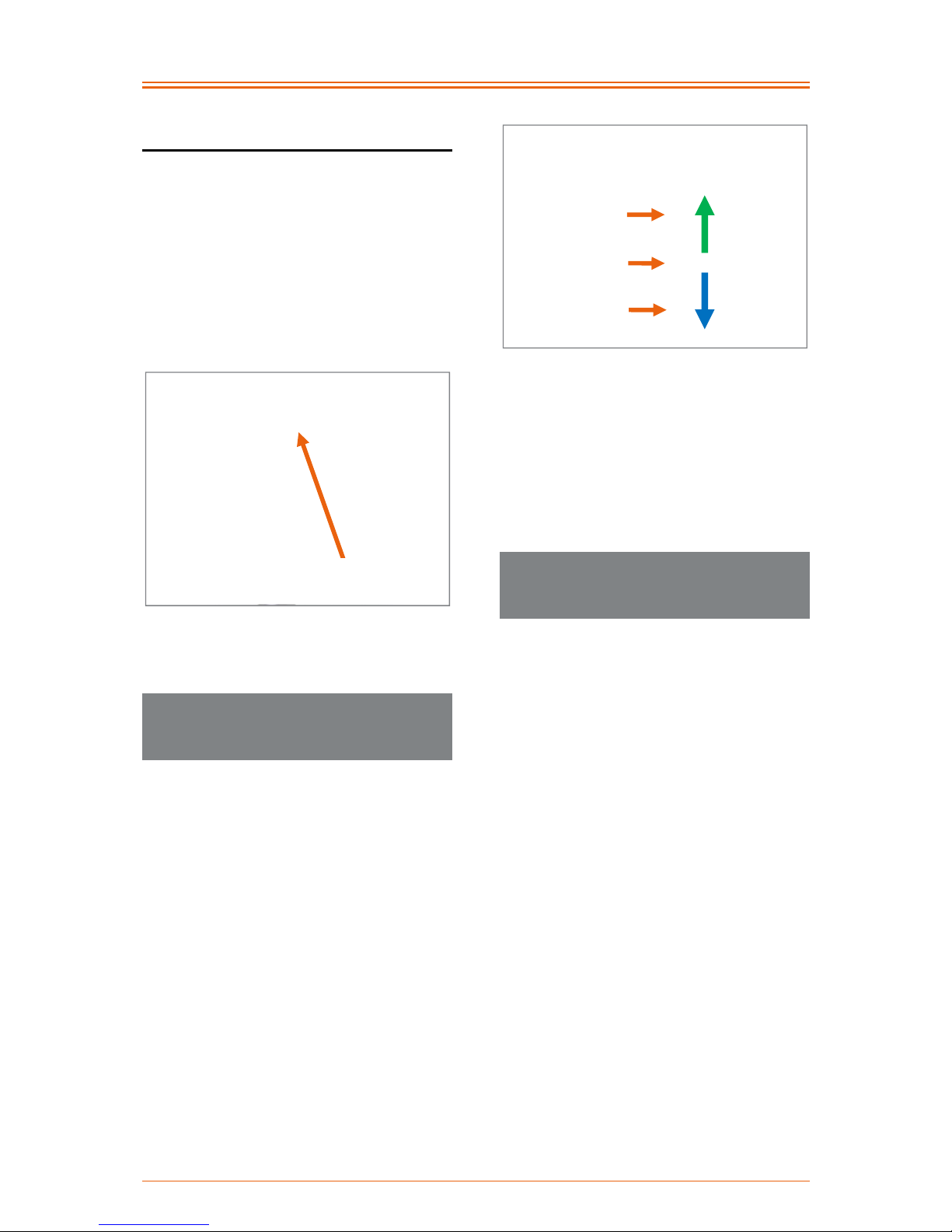
18 Individual setting options
A possible adjustment of the seat position is
only possible if the product has been fitted with
angle-adjustable caster wheel bearing
blocks (cannot be retrofitted). In this case, the
seat tilt and/or the seat height at the front
can be adjusted. This setting is carried out via
the position of the caster wheels in the caster
wheel fork and the caster fork size. Otherwise,
there are not further adjustment possibilities
available.
Figure 1: Angle-adjustable caster wheel bearing
block
18.1 Adjusting the seat height at the
front by positioning the caster
wheels in the caster wheel fork
Adjusting the front seat height or angle of seat
can be carried out via the positioning of the
caster wheel in the caster wheel fork.
Generally, the caster wheel forks have three
possible positions that can be used to change
the front seat height in steps of 15 mm.
If the angle of seat has to be increased or
the front seat height increased, the caster
wheel is mounted in the caster fork in a
lower position.
If the angle of seat has to be reduced or
the front seat height decreased, the caster
wheel is mounted in the caster fork in a
higher position.
Figure 2: Three positions in the caster fork for
positioning the caster wheel and its effect on the
front seat height
The instructions for disassembly and assembly
of the caster wheels can be found in
chapter 23.1.
18.2 Adjusting the seat height at the
front by changing the caster
wheel fork
If the adjustment range of the cater fork
present is insufficient, you can use the use the
next longer or shorter one.
In doing so, the bottom position of the fork size
1 is equivalent to the top position of fork size 2
and the bottom position of fork size 2 to the top
position of fork size 3.
Top position
Middle position
Bottom position
Increase
angle of
seat/front
seat height
Reduce
angle of
seat/front
seat height
Angle-adjustable caster
wheel bearing block
Page 15

Operating instructions SPEEDY F4 & F2
14
Figure 3: Caster fork sizes with marking of the same
seat height settings with different caster fork sizes
The instructions for replacing the caster forks
can be found in chapter 23.3.
When changing the angle of seat or front seat
height each time:
the wheel track of the drive wheels must
be checked and readjusted if necessary
(see chapter 22.2).
the caster wheel axles must be readjusted
(see chapter 23.4).
the backrest angle may have to be
repositioned (see chapter 19.1).
make sure the clearance under the footrest
is sufficient. Experience shows that this
should not be less than 4 cm (see
chapter 24).
if necessary, the height of the anti-tipping
support may have to be readjusted (see
chapter 25.3).
19 Back system
Avoid falling into the seating and back
padding/back shell as it significantly increases
the risk of an adjustment, falling down or
defects.
19.1 Backrest angle
19.1.1 Adjustment possibilities with
backrests fixed by being bolted
onto side panels
With backrests screwed permanently onto side
panels, there are no possibilities for flexible
backrest adjustment without tools available.
Figure 4: Backrest screwed permanently onto side
panels, equipped with Carbon side parts with
integrated clothing protection
Depending on the type of the frame and
equipment, a permanent adjustment of the
backrest of 5° forwards or backwards is
possible using tools however. It is not possible
to make this adjustment with the Overlite frame
version with complete seat and backrest made
from one bended tube (SPEEDY F2). This
adjustment is possible in the frame versions of
the product with a separate back unit which are
also fitted
with an "Aluminium side panel", or
with an "Aluminium side panel with
screwed on clothing protection", or
with an "Aluminium side panel with
integrated clothing protection".
There are three holes in the rear of the side
panel on the top and bottom to position the
backrest tube. To adjust the backrest 5°
Size 3
185 mm
Size 2
155 mm
Size 1
125 mm
125 mm
Page 16

Operating instructions SPEEDY F4 & F2
15
forwards or backwards, loosen both M5
fastening bolts (AF 3 mm) with washers on
each side and position the fastening bolts with
washers in the desired holes of the side panels
(use the same hole on the right and left). Then
tighten up the M5 fastening bolts (AF 3 mm)
again to 4 Nm and secure these with thread
lock fluid.
Figure 5: Adjusting the backrest position using holes
in the side panel or the clothing protection
19.1.2 Adjustment possibilities with an
adjustable backrest
If equipped with an adjustable and foldable
backrest, the backrest angle can be flexibly
adjusted without using tools and the backrest
can be completely folded away. The angle of
the backrest can be fixed in 7 positions.
Observe that the centre of gravity is
shifted further to the rear by the enlargement of
the angle between the backrest and the seat
system and thus, the tipping point of the
product is reached much sooner.
19.1.3 Instructions for sitting posture with
an adjustable backrest
For a good sitting posture, we recommend
positioning the backrest vertical to the ground,
where possible.
With low backrest with adaptable belt cover
due to a disability, under certain
circumstances, it may also be a benefit for a
good sitting stability to slightly tilt the backrest
to the front and to slacken the top belt of the
back padding so that the slack in the upper
area is greater (see chapter 19.2).
The adjustment possibility of the backrest
angle supports active sitting and ensures for
flexibility of the wheelchair user. An example in
the following:
if the angle of the seat has been changed
(see chapter 18), the angle of the backrest
can be respectively readjusted.
When driving on slopes and when
transporting baggage (e.g. backpacks) on
the backrest, the centre of gravity shifts
more to the rear and the risk of tipping
increases. Then this can be counteract ed
by a respective angle adjustment of the
backrest to the front.
For comfortable seating, the backrest can
be locked in a position to the rear so that
the backrest is tilted slightly back.
19.1.4 Adjusting the backrest angle or
folding down the backrest with an
adjustable backrest
To adjust the backrest angle, relieve this
(otherwise there is a risk of tipping) and then
loosen the locking pin that engage in the
locking holes of the side section on the left and
right. For this purpose, grasp under the seat
upholstery and in the middle, pull the cord to
the front that is linked to the locking pin.
Figure 6: Locking pin connected to a cord (viewed
from the inside of the frame)
Locking pin
Three holes on
the top and the
bottom to adjust
the backrest
p
osition
M5 fastening bolts
with washers
Page 17

Operating instructions SPEEDY F4 & F2
16
Figure 7: Locking pin engages in the locking hole in
the side section (view from the outer side of the
product)
Figure 8: Cord for operating the locking pin and thus
for adjusting the angle of the backrest
If you have released both locking pins by
pulling on the cord, you can adjust the backrest
as desired and re-engage it by letting go of the
cord. In doing so, before applying load again,
make sure that both locking pins have
engaged safely into the desired locking holes
(the same position on the right and left).
For safety reasons, the adjustment range of
the backrest is limited by a stop pin when
supplied. The stop pin allows a maximum
inclination of 7° to the rear from a vertical
position.
Figure 9: Stop pin
Depending on the adjustment of the
backrest angle, check the tight engagement of
the backrest via the locking pins.
To fold down the backrest, pull on the middle
of the cord towards the front, and at the same
time, fold the backrest downwards until it rests
on the seating area. If you want to return the
backrest back to the desired angle, proceed as
described at the beginning.
19.2 Adjustable back padding & their
adjustment options
The back system "Adjustable back padding"
comprises one belt system and one back
upholstery. The slack of the backrest can be
adapted to the individual requirements via the
belts with tensioning loops.
First remove the back upholstery that has been
covered over which has been attached using
hook-and-loop straps. The belt system located
underneath has been set in the factory that the
top and the bottom belts have a slack of
approx. 2 cm. The middle belts have been
pulled tight for a good lumbar support.
Cord
Locking pin
Pull from the
middle to the front
Stop pin
Page 18

Operating instructions SPEEDY F4 & F2
17
Figure 10: Belt system of the adaptable back
padding with three belts
Figure 11: Belt system of the adaptable back
padding with four belts
To adjust the slack in the belt system, the
tensioning loops of the respective belt are held
on their strap and pressed (strongly) to the
right until the belt slackens.
Figure 12: Push the tensioning loop onto its strap on
the right
Figure 13: Tensioning loop open completely
Now the belt can be pulled tight for setting a
small slack or loosened for a large slack
(Fig. 14 and 15). The belt does not have to be
threaded out of the tensioning loops for this.
Figure 14: Reduce the slack
Figure 15: Increase the slack
In order to put the tensioning loops back onto
the back system loosely again, pull the loop
section at the back to the left. You should dose
your pulling force with care in order not to
adjust the set slack again.
Top belt
Bottom belt
Middle belt
Pull to the right:
Increase the slack
Tensioning loop with strap
Press to the
right
Pull the rear loop part to the left:
Reduce the slack
Top belt
Bottom belt
Middle belts
Page 19

Operating instructions SPEEDY F4 & F2
18
Figure 16: Then re-apply the tensioning loops back
on the back system
Figure 17: Tensioning loops applied slightly to the
back system
Then re-mount the back upholstery using the
fleece hook-and-loop straps.
If the belt should have mistakenly been
threaded out during the adjustment, see the
following figures for threading the belt in
correctly:
Figure 18: Step 1: Threading in the belt
Figure 19: Step 2: Threading in the belt
Figure 20: Step 3: Pulling the belt through
Figure 21: Step 4: Simple threading in of the belt
through the tensioning loops
The belts must always be threaded
through the tensioning loops twice, otherwise
the belts will slacken when using the product,
and with heavy loads, the middle web of the
tensioning loops will sag strongly.
Pull the rear loop part
to the left
Page 20

Operating instructions SPEEDY F4 & F2
19
Figure 22: Step 5: Returning the belt through the
tensioning loop to obtain the required "double
passage"
Figure 23: Step 6: Pulling the belt through for the
double passage
Figure 24: Step 7: Double passage
Figure 25: Step 8: Threading in the belt
Figure 26: Step 9: The belt has been fully threaded
19.3 Ergonomic back shell & its setting
options
The back system "Ergonomic back shell"
comprises an aluminium shell, Velcro crossstraps and a back padding.
There is already a slack integrated in the back
shell due to the shape of the back shell.
Nothing can be adjusted here.
However, lumbar support can be achieved
using the Velcro cross-straps. For this
purpose, the back padding is removed over the
Velcro straps. Now the cross-straps can be
tensioned to the respective individual
requirements by undoing and reapplying the
Velcro strap system.
Leave the loop
Page 21

Operating instructions SPEEDY F4 & F2
20
Figure 27: Ergonomic back shell (view from behind)
Figure 28: Ergonomic back shell without back
padding with Velcro cross-straps (view from the
front)
Then mount the back upholstery using the
Velcro straps.
19.4 Ergo Back backrest bracket and
its adjustment possibilities
The back system "Ergo Back backrest bracket"
normally consists of a backrest bracket (with or
without lumbar curvature) and an adjustable
backrest support including customised
backrest upholstery. The adjustment
possibilities of the adjustable backrest
support are described in chapter 19.2.
Figure 29: Ergo Back backrest bracket with
adjustable backrest support, backrest upholstery
fitted
Figure 30: Ergo Back backrest bracket with
adjustable backrest support with four belts, backrest
upholstery removed
The Overlite frame version of the SPEEDY
F2 has a special version of the Ergo Back
backrest bracket. In this case, there is no
adjustable backrest support under the backrest
upholstery, rather a backrest support which is
fixed to the frame tubes using Velcro tapes.
There are no possible adjustments here.
Velcro cross-straps
Top belt
Bottom belt
Middle
belts
Page 22

Operating instructions SPEEDY F4 & F2
21
Figure 31: Ergo Back backrest bracket with backrest
support on SPEEDY F2 Overlite, backrest
upholstery fitted
Figure 32: Ergo Back backrest bracket with backrest
support on SPEEDY F2 Overlite, backrest
upholstery removed
If the Ergo Back backrest bracket is fitted with
a back shell instead of the adjustable backrest
support, the adjustment possibilities described
in chapter 19.3 apply.
Figure 33: Ergo Back backrest bracket with back
shell
20 Seat system
Avoid falling into the seating and back
padding/back shell as it significantly increases
the risk of an adjustment, falling down or
defects.
The seat system generally either comprises a
spring suspended Body Contour seat
upholstery or an open belt system.
With a seating system from Body Contour
seat upholstery, there is no adjustment
option. The Body Contour seat upholstery has
a springing effect and when seating.,
automatically forms a slack.
Figure 34: Body Contour seat upholstery
The open belt system can be subsequently
adjusted. Using the fleece hook-and-loop
straps, the slack in the seating surface can be
changed so that it suits your seat cushion
system. In doing so, the seat tension should
not have too much slack to avoid touching the
frame cross tubes.
Figure 35: Open belt system with fleece hook-andloop straps for adjusting the slack
Page 23

Operating instructions SPEEDY F4 & F2
22
It is mandatory to use a seat cushion on
the seating system. At cold temperatures, the
seat cushion prevents lower abdomens from
undercooling and protects against dirt and
wetness. Moreover, the cushion ensures
uniform pressure distribution for your bottom
and absorbs impacts as well as vibrations.
21 Clothing guard
21.1 Side panel with integrated
clothing guard
In the version of the product with a "side panel
with integrated clothing guard", the side panel
and the clothing guard are made in one piece
and bolted onto the backrest and product
frame. There is no possibility to remove the
clothing guard and no possibility to adjust the
clothing guard from its position to the drive
wheel.
Figure 36: Side panel with integrated clothing guard
(shown without the drive wheel)
21.2 Side panel with bolt-on clothing
guard
21.2.1 Overview of terms
If the product is fitted with a "side panel with
bolt-on clothing guard" the clothing guard is
fitted on each side with two M5 mounting bolts
(AF 3 mm) with washers and two clothing
guard brackets are screwed onto the side
panel.
Figure 37: Side panel with bolt-on clothing guard
and M5 mounting bolts (shown without the drive
wheel)
Figure 38: Clothing guard mount
21.2.2 Removal and attachment of the
clothing guard
The clothing guard can be removed on each
side by loosening the two M5 mounting bolts
(AF 3 mm) with the washers and removing the
two clothing-guard brackets.
21.2.3 Adjusting the clothing guard
position
To adjust the clothing guard's position to the
drive wheel, the hole pattern in the front area
of the clothing guard can be used. To do this,
loosen the front M5 mounting bolt (AF 3 mm)
with washer on both sides. Position the
clothing guard as desired and insert the M5
mounting bolt with washer in the corresponding
hole of the hole pattern and into the clothing
guard bracket. Tighten up the M5 mounting
bolt (AF 3 mm) to 4 Nm.
Rear M5 mounting bolt with
washer
Front M5 mounting bolt with
washer
Clothing guard mount
Page 24
Operating instructions SPEEDY F4 & F2
23
Figure 39: Hole pattern to adjust the clothing guard
position (shown without drive wheel)
21.3 Clothing guard removable via lock
function
21.3.1 Overview of terms
Figure 40: Back jointed shaft
Figure 41: Clothing guard removed from the product
Figure 42: Clothing guard fitted to the product
(product equipped with integrated brake or with
cable brake without brake retaining rail, shown
without drive wheel)
Figure 43: Clothing guard fitted to the product
(product equipped with knee-lever brake with brake
retaining rail, shown without drive wheel)
Figure 44: Locking pin engages in the locking hole
in the side part (shown without clothing guard and
equipped with an integrated brake)
Side panel guide
Back jointed shaft
Back jointed shaft
Locking pin
Side panel guide
Mounting bar
Recess for
"side panel guide"
Recess for "back
jointed shaft"
Mount for the
"locking pins"
Back jointed shaft
Side panel guide
Hole pattern to
adjust the clothing
guard position
Page 25

Operating instructions SPEEDY F4 & F2
24
Figure 45: Locking pin engages in the locking hole
in the side part (shown without clothing guard and
equipped with an knee-lever brake
)
Figure 46: Locking pin engaged in the mounting bar
of the clothing guard (view with clothing guard)
21.3.2 Removal and attachment of the
clothing guard
To remove the clothing guard, the locking
pin must be pulled out of the mounting bar first.
For this purpose, grasp under the seat
upholstery and in the middle, pull the cord to
the front that is linked to the locking pin and
keep it in this position.
Figure 47: Locking pin (view from the inside of the
frame) linked to the cord
Figure 48: Cord for pulling the locking pin
Observe: In case you are sitting in the
product when removing the clothing guard, you
have to relieve the backrest before pulling the
cord.
Now, first the clothing guard can be removed
from the side panel guide for the mounting bar
(then the cord can be released again) and
pulled from behind the back joint shaft.
Locking pin
engaged in the
mounting bar
Locking pin
Cord
Pull from the
middle to the front
Locking pin
Side panel guide
Page 26

Operating instructions SPEEDY F4 & F2
25
Figure 49: Clothing guard pulled from the side panel
guide to the front (shown without drive wheel)
To mount the clothing guard, this is first
connected to the rear of the back joint shaft
with the mounting bar, then the mounting bar is
inserted at the front in the side panel guide and
pressed downwards until the locking pin
engages in the mounting bar.
Figure 50: Mounting bar pinned on the rear pivot
shaft (shown without drive wheel)
21.3.3 Adjusting the clothing guard
position
After changing to different tyres, the clothing
guard position may need to be adjusted to suit
the wheel arch. The distance between the
tyres and the clothing guard should be
between 5 and 8 mm to avoid pinching your
fingers, scraping the tyres on the clothing
guard, and obstruction when grasping the
handrim.
To adjust the clothing guard position, loosen
the two M5 fixing screws (AF 3 mm) from the
clothing guard mount on each of the clothing
protection guards.
Figure 51: Clothing guard mount
Figure 52: M5 fixing screws and slots on the
mounting bar
Now the mounting bar can be brought into
position using the slots of the clothing guard
and the mounting bar.
Finally the clothing guard mounts are
positioned accordingly and the M5 fixing
screws (AF 3 mm) are screwed back into the
clothing guard mounts with 4 Nm.
Figure 53: Slots of the clothing guard
Slots of the clothing guard
M5 fixing screws
Clothing guard
mount
Slots of the
mounting bar
Page 27

Operating instructions SPEEDY F4 & F2
26
21.3.4 Clothing guard size
The clothing guard is available in three
different sizes. The dimensions of the wheel
arches differentiate with the different sizes:
Aluminium: 30 mm (Size 1), 36 mm
(Size 2), 46 mm (Size 3)
Carbon: 30 mm (Size 1), 36 mm (Size 2),
42 mm (Size 3)
Figure 54: Dimensions of the wheel arches
The size of the clothing guard can be read-off
the notches on the bottom edge of the clothing
guard. One notch means size 1, two notches
mean size 2 and three notches mean size 3.
Figure 55: Size marking on the clothing guard
After changing to a wider tyre size or after
changing the wheel camber, it may be
necessary to change to another clothing guard
size. Where required, such a change may be
arranged by your rehabilitation specialist
dealer.
22 Drive wheels
22.1 Removing and attaching the drive
wheels
Figure 56: Locking knob of the quick-release axle in
the middle of the wheel axle
To remove the drive wheels grip through the
spokes around the wheel hub with your fingers.
By pressing the locking knob in the middle of
the wheel axle with your thumb, the wheels
can then be removed.
When attaching the drive wheels, the locking
knobs must be pressed and the drive wheels
with quick-release axle must be inserted in the
drive wheel bearings. When doing this, special
attention should be paid to ensure that the
locking knob springs out again after attaching
the wheel, as otherwise the wheels are not
properly secured. You will know this if you can
see the index groove.
Figure 57: Quick release axle with index groove
Before using the product, check if the
wheels are secured and that the quick release
axles are locked.
Locking knob of the
quick-release axle
Index groove
Size marking for size 2
Dimensions of the wheel arches
Page 28
Operating instructions SPEEDY F4 & F2
27
For quadriplegics, or people with limited
finger function, a Tetra Clip is available to
operate the quick release axle lock. The Tetra
Clip is a plastic box which is screwed onto the
drive wheel hub and operated via a pushthrough pin. The pin has a red marking on one
side (quick release axle opened) and a green
marking on the other side (quick release axle
locked). The pin can be pushed using the ball
of your hand in the direction of the middle of
the drive wheel and thereby the quick release
axle opened or closed.
Figure 58: Tetra Clip with locked quick release axle
Figure 59: Tetra Clip with opened quick release
axle, drive wheel can be removed
22.2 Checking and adjusting the wheel
tracking of the drive wheel
Well adjusted wheel tracking significantly
improves the easy running characteristics of
the product. To check the tracking, proceed as
follows:
Position the product on a level surface and
secure the product against rolling away.
Measure the axle heights (from the ground to
the drive wheel axle) and write this dimension
onto both tyres at front and back.
Figure 60: Drawing the axle height on the front and
back of both tyres
Afterwards measure the distance between the
drive wheels front and back at the height of the
axles along the markers. Ideally, the distance
between the two drive wheels should be the
same size at the front and back. In general it
can be said that the distance between the drive
wheels at the front may not be larger than at
the back. Apart from that, the distance at the
back may not be more than 5 mm larger that at
the front. If this is not the case, the wheel
tracking needs to be corrected.
Figure 61: Distance between the markers on the
tyres (at axle height), back
•
Axle height
Distance
Drawing the axle height onto tyres
Markings
Red marking = drive
wheel can be removed
Green marking = drive wheel is
locked in place on the product
Page 29

Operating instructions SPEEDY F4 & F2
28
To adjust the track proceed as follows:
1. Loosen the aluminium locking nuts on both
sides (AF 41 mm).
Figure 62: Drive wheel bushing and aluminium
locking nut (rear view)
2. Correctly adjust the track by turning the
drive wheel bushing (AF 22 mm). Here it
can be said that: If you turn the drive wheel
bushing in the direction of travel, the track
at the front will become more narrow. The
exact opposite occurs if you turn it against
the direction of travel, the track opens up.
3. Make sure that the distance at the front to
the frame on the right and left is the same.
Figure 63: Front distance to the frame
(SPEEDY F4 and F2 with classical frame geometry)
Figure 64: Front distance to the frame
(SPEEDY F2 oversized)
4. Measure the distance between the drive
wheels at the front and back again at the
axle height (along the markers) so that the
distance between the rive wheels is not
any larger at the front than at the back.
Apart from that, the distance at the back
may not be more than 5 mm larger that at
the front.
Figure 65: Distance between the markers on the
tyres (at axle height), back
5. If all the distances are correct, then use an
open-ended spanner (AF 22 mm) to hold
the running wheel bushing in position and
tighten the aluminium locking nut (AF
41 mm) with a tightening torque of 70 Nm.
Drive wheel bushing
Aluminium locking nuts
Distance
Markings
Distance at front to
frame the same
size on both sides
Distance at front to
frame the same
size on both sides
Page 30

Operating instructions SPEEDY F4 & F2
29
22.3 Wheel camber
The wheel camber increases the lateral
stability of the product but also increases the
overall width of the product.
The wheel camber will be carried out according
to the order and can be subsequently changed
on angle-adjustable caster wheel bearing
blocks by replacing the drive wheel bearings
(with integrated wheel camber). If you want to
make a change to the wheel camber, please
contact your rehabilitation specialist dealer or
PRO ACTIV.
22.4 Air pressure
Check the tyre inflation pressure at regular
intervals as well as after extreme influence of
temperature (not on solid rubber tyres). The
maximum and if applicable, minimum tyre
pressure is printed on the side of the tyre.
This should be observed.
If the tyre pressure is too low, then optimal
functionality of the knee lever brake is not
ensured. Apart from that, there is an increased
risk of a flat tyre.
The tyre pressure increases with the
temperature. If the pressure is too high, the
tyre may burst. For this reason, product tyres
may not be exposed to unusually high
temperatures such as in a sauna or under
glass in the summer.
When inflating the tyre, make sure that the
prescribed air pressure is not exceeded.
To check or correct the air pressure,
proceed as follows:
1. Secure the product to prevent it rolling
away.
2. The drive wheel is normally fitted with a car
tyre valve. Unscrew the valve cap.
Figure 66: Valve with cap
Figure 67: Valve without cap
3. Place the valve attachment of the
compressed air device or the compressor
onto the valve (if necessary, an adapter
must be placed on the valve attachment)
and, if a clamp lever is fitted, secure the
connection by applying the lever.
4. Now check the air pressure . If the air
pressure does not match the
specifications, now correct the air
pressure.
5. Finally release the clamp lever (if present),
pull the valve attachment off the valve and
replace the valve cap.
Valve with cap
Cap removed
Page 31

Operating instructions SPEEDY F4 & F2
30
Figure 68: Compressor
Figure 69: Valve adapter and clamp lever of the
compressor
22.5 Wheelbase extension
22.5.1 Wheelbase extension welded in
place (SPEEDY F2 oversized)
The "wheelbase extension welded in place"
cannot be removed.
Figure 70: Wheelbase extension welded in place
(SPEEDY F2 oversized)
For changing the drive wheels between the
wheelchair axle and the axle of the wheelbase
extension, proceed as described chapter 22.1.
22.5.2 Removable wheelbase extension
A "Removable wheelbase extension" can be
used with the product as long as a base plate
(cannot be retrofitted) is present on the
product.
Figure 71: Base plate and pivot point on the product
(viewed from the below on the side and without a
drive wheel)
Figure 72: Description overview with "Removable
wheelbase extension"
Jaws
Axle of the wheelbase extension
Quick Pin
Notch
Pivot point
Base plate
Valve adapter
Clamp lever
Page 32

Operating instructions SPEEDY F4 & F2
31
Figure 73: Quick Pin of the wheelbase extension
with locking knob
Figure 74: Jaws of the wheelbase extension
To attach the wheelbase extension, guide
the jaws under the wheelchair axle and insert
this on both sides to the pivot point. Now lift up
the wheelbase extension until the base plate is
positioned in the appropriate notch in the
wheelbase extension. Hold the wheelbase
extension in this position and insert the Quick
Pins on the right and left. Now the wheelbase
extension is fixed tight.
Figure 75: Wheelbase extension attached (view
from the side without drive wheel)
Figure 76: Wheelbase extension applied, Quick Pins
inserted (view from the rear)
To remove the wheelbase extension, hold it
firmly, press on the locking knobs of the Quick
Pins and remove both Quick Pins from the
wheelbase extension. Loosen the jaws of the
wheelbase extension from the pivot point on
both sides by moving the wheelbase extension
slightly downwards and pull it away from the
product to the rear.
Figure 77: Quick Pin locking knob
The Quick Pins can then be inserted in the
holes of the wheelbase extension to prevent
them getting lost (Fig. 72).
For changing the drive wheels between the
wheelchair axle and the axle of the wheelbase
extension, proceed as described chapter 22.1.
Jaws on the pivot point
Quick Pin
with locking
knob
Jaws
Base plate in the notch
Quick Pins inserted
Base plates in the notches
Locking knob
Page 33

Operating instructions SPEEDY F4 & F2
32
Figure 78: Wheelchair axle and wheelbase
extension axle
22.6 Other
If tyres, inner tubes or handrims need to be
replaced, please contact your rehabilitation
specialist retailer.
Please note that changing one type of tyres to
another size is only possible with versions with
adjustable caster-wheel bearing blocks (cannot
be retrofitted), as with welded caster-wheel
bearing blocks the frame design including the
alignment of the caster-wheel bearing blocks is
precisely aligned to the tyre size ordered and
the welded caster-wheel bearing blocks cannot
subsequently be adjusted.
Figure 79: Angle-adjustable caster wheel bearing
block
We recommend: The spoke guard
prevents hands and fingers entering and being
trapped in the wheels when riding. The risk of
injury is thus minimised.
Figure 80: Spoke guard for minimising the risk of
hands and fingers getting trapped
23 Caster wheels
23.1 Replacing the caster wheels
The caster wheels of the product are,
depending on the type of casters, either
fastened with two M6 axle fixing screws or one
M6 axle fixing screw and a M6 nut.
23.1.1 Replacing the caster wheels when
mounted using two axle fixing
screws
To remove a caster wheel, unscrew the M6
axle fixing screws (AF 4 mm) on one side.
Figure 81: M6 axle fixing screw on caster wheel axle
M6 axle fixing screws
Angle-adjustable caster
wheel bearing block
Axle of the wheelbase extension
Wheelchair axle
Page 34

Operating instructions SPEEDY F4 & F2
33
Figure 82: Caster wheel with aluminium hexagon
socket
Now you can see the aluminium axle with a
hexagon socket (AF 4 mm) in the middle of the
axle. This hexagon socket is used to fix the
axle in place, while the second M6 axle fixing
screw (AF 4 mm) is unscrewed. To do this,
insert an Allen key (AF 4 mm) into the hexagon
socket on the aluminium axle and hold it still.
At the same time, unscrew the remaining M6
axle fixing screw (AF 4 mm) on the other side.
Now the caster wheel can be removed from
the fork. One spacer each is mounted to the
right and left on the caster wheel that you are
able to remove in order for it to be reused later
when reinstalling the new caster wheel. In case
you want to install a different type of caster
wheel, use the enclosed spacers as these
generally differ from one type of caster wheel
to another.
Figure 83: Spacer on the caster wheel
To mount the caster wheel, proceed in the
reverse order as for removal. Please make
sure that the spacers on the right and left on
the caster wheel are re-installed in the caster
fork before assembly. The torque of the M6
axle fixing screws (AF 4 mm) is 7 Nm. It is
recommended only to use screws with polymer
dry locking coating. Screws without polymer
dry locking coating must be secured with screw
locking fluid.
23.1.2 Replacing the caster wheels when
mounted using an axle fixing screw
and nut
To remove the caster wheel, hold the M6 nut
(AF 10 mm) firmly and loosen the M6 axle
fixing screw (AF 4 mm). Now you can remove
the M6 nut and washer, the M6 axle fixing
screw with washer and the caster wheel.
Figure 84: M6 axle fixing screw (viewed from the
outside of the product)
Figure 85: M6 nut (viewed from the inside of the
product)
Aluminium axle with
hexagon socket
Spacer
M6 axle fixing screw with
washer
M6 nut with washer
Page 35

Operating instructions SPEEDY F4 & F2
34
Figure 86: Caster wheel axle with aluminium axle
Figure 87: Spacer on the caster wheel
When mounting the caster wheel, position
the caster wheel with its spacers in the caster
wheel fork, hold it in position and insert the M6
axle fixing screw with its washer from the
outside of the product to the inside through the
axle of the caster wheel. Now attach the
washer and the M6 nut (AF 10 mm) from the
other side. The tightening torque of the axle
fixing screws (AF 4 mm) is 7 Nm.
23.2 Caster wheels flapping
Uncontrolled swivelling backwards and
forwards of the caster wheels around their
axes on the caster fork (while moving) is
known as "fluttering".
If the caster wheels start fluttering, then
immediately reduce the speed you are
travelling at to avoid the caster wheels
jamming sideways so as to avoid the risk of
falling over.
The speed limit where caster wheel fluttering
starts, is reduced by:
increasing size of the caster wheels
increase weight of the caster wheels
falling load on the caster wheels
decreasing caster length of caster wheels
The following options are available to
counteract caster fluttering generally:
When equipping the product with angle-
adjustable caster-wheel bearing blocks,
the fluttering can be reduced by reducing
the diameter of the caster wheels. This
means installing a small caster wheel in a
different wheel position in the caster wheel
fork (seat height thus remains the same)
would be one way of reducing fluttering.
However, please note that using a smaller
caster wheel makes it more difficult to
overcome obstacles and makes tipping
necessary more often. The smaller the
caster wheel is, the more driving skill is
required.
Another way to reduce the fluttering is the
use of a lighter caster wheel of the same
diameter, or, as previously described,
with a smaller diameter (smaller diameter
only possible where the product has been
fitted with angle-adjustable caster-wheel
bearing blocks).
Spacer
Aluminium axle
Page 36

Operating instructions SPEEDY F4 & F2
35
Figure 88: Caster length
When fitting the product with angle-
adjustable caster-wheel bearing blocks,
the caster length can be increased. The
caster length is the distance between the
rotary axle of the caster wheel fork
projected onto the floor and the wheel
contact point. The wheel contact point of
the caster wheel trails behind the rotary
axle as it were. The caster length has a
stabilizing effect on moving in a straight
line. Increasing the caster length can be
attained by mounting the caster wheel in a
different wheel position on the caster
wheel fork (the in doing so, the front seat
height or the angel of the seat changes,
see chapter 18). Another possibility is to
bend the caster wheel axle (see
chapter 23.4) forwards in the direction of
travel in the lower area. The angle of the
caster wheel axle can be adjusted up to
approximately 4 mm over the length of the
caster wheel bearing block out of the
vertical. This increases the caster length
and the tendency to vibrate reduces.
Figure 89: Increased caster length via the inclination
of the caster wheel axle
23.3 Replacing the caster wheel forks
A distinction needs to be made between the
caster wheel forks with a screwed axle and
those with a quick-release axle.
In addition, the replacement of the caster
wheel forks with screw-on axles differs from
the angle-adjustable caster-wheel bearing
blocks and welded caster-wheel bearing
blocks.
Caster wheel for rotary axle
Caster length
Wheel contact
point
Increased caster length
Wheel contact
point
Caster wheel for rotary axle tilted
maximum in the direction of travel
Max.
4 mm
Page 37

Operating instructions SPEEDY F4 & F2
36
23.3.1 Caster wheel fork with screw-on
axle on angle-adjustable casterwheel bearing blocks
To remove the caster wheel fork with screwon axle, the aluminium cap on the caster wheel
bearing block must first be removed. In order
to release the cap, you can run under the cap
using a commercially available cutter knife and
lift slightly at several points. Then the M12 nut
(AF 19 mm) is loosened using, e.g. an AF
19 mm socket. Now the caster wheel for rotary
axle can be pulled out from under the caster
wheel bearing block.
Figure 90: Aluminium cap
Figure 91: Aluminium cap removed and M12 nut
visible
To assembly the caster fork with screw-on
axle, this is inserted with the caster wheel axle
into the caster wheel bearing block. Then the
M12 nut (AF 19 mm) is tightened again to
3 Nm and secured with thread lock fluid. Then
the aluminium cap is pressed back onto the
caster wheel bearing block.
For the rotary axle to run smoothly, the M12
nut must not be tightened to more than 3 Nm.
In case more sluggishness is desired, this can
be achieved using a higher tightening torque.
23.3.2 Caster wheel fork with screw-on
axle with welded caster wheel
bearing blocks
To remove the caster wheel fork with screwon axle, a wrench is used which is included in
the scope of delivery. This wrench is inserted
into the two holes on the nut of the caster
wheel bearing block and turned anti-clockwise,
e.g. using an AF 24 mm fork wrench. The
caster wheel fork needs to be held still. When
the nut has been completely removed, the
caster wheel fork can be pulled out.
Figure 92: Loosen the nut of the caster wheel axle
using the wrench
Figure 93: Caster wheel axle nut completely
removed
M12 nut
Aluminium cap
Wrench
Caster wheel
bearing block
Nut on the
caster wheel
axle
Page 38

Operating instructions SPEEDY F4 & F2
37
When mounting the caster wheel fork with
screw-on axle, insert the caster wheel axle
back into the caster wheel bearing block, use
the supplied wrench to tighten up the nut of the
caster wheel axle again (hold the caster wheel
axle firmly) and secure it with thread lock.
The nut of the caster wheel axle may not be
tightened up more than 3 Nm to ensure it runs
smoothly. In case more sluggishness is
desired, this can be achieved using a higher
tightening torque.
23.3.3 Caster wheel forks with quickrelease axle
To remove the caster wheel fork with a
quick-release axle, a locking knob between the
caster wheel and the caster wheel fork's inner
side is used. Grasp around the caster fork and
press the locking knob with your thumb. The
caster wheel fork can now be pulled out.
Figure 94: Caster wheel fork with quick release axle
and locking knob
To mount the caster wheel fork with a quickrelease axle, press the locking knob again and
insert the caster wheel axle back into the
caster wheel bearing block. When doing this,
pay special attention to ensure that the locking
knob springs all the way out again after
attaching the wheel, otherwise the wheels are
not properly secured. You will know that if you
can see the index groove (Fig. 57).
23.4 Adjusting the caster wheel axles
(when fitted in angle-adjustable
caster-wheel bearing blocks)
To ensure that the product has good properties
when steering and driving straight ahead, the
caster wheel axle should be adjusted to be
vertical to the level ground.
Adjustments on the caster wheel axles can be
required for the following reasons:
The tipping point and/or sitting heights
have been changed.
The caster wheel axles are no longer
vertical due to a fall or an impact.
The flattering of the caster wheels should
be reduced.
To adjust the caster wheel axle, the product
should be placed on a level surface and the
wheel track of the drive wheels must have
already been adjusted (see chapter 22.2).
Now check to see if the caster wheel axles are
standing vertically to the level ground. For this
purpose, place an angle with height adjustable
slider on the front edge of the caster wheel
bearing blocks. The slider should be aligned at
the middle of the caster wheel bearing block.
If the front edges of the caster wheel
bearing blocks are vertical to the level ground,
then the caster wheel axles are also doing this.
Observe that the front edges of the caster
wheel bearing blocks are slightly rounded.
Thus, the distance above and below between
the slider of the angle and the front edge of the
caster wheel bearing blocks must be the same
size.
Locking knob on
inside of fork
Page 39

Operating instructions SPEEDY F4 & F2
38
Figure 95: Checking the adjustment of the caster
wheel axles
The angle with slider can be ordered from
PRO ACTIV (order number: 8000 901 000).
If the front edges of the caster wheel bearing
blocks are not standing vertical to the level
ground, the settings must be adjusted. First
adjust the right caster wheel bearing block,
then the left one, and finally check the right
side again. To do this, proceed as follows:
1. Loosen the M5 stud bolt (AF 2.5 mm).
Figure 96: M5 stud bolt
2. Undo the M6 fixing screws (AF 5 mm)
slightly on the frame inner side.
Figure 97: M6 fixing screws on the frame inner side
3. Now slightly loosen the M6 fixing screw
(AF 5 mm) on the outside of the frame.
Figure 98: M6 fixing screws on the frame outer side
4. Using the aid of the angle, move the caster
wheel bearing block in a vertical position to
the level ground.
5. Tighten the M6 fixing screws (AF 5 mm)
again on the frame outer and inner side to
a tightening torque of 10 Nm and recheck
the vertical setting.
6. Screw the M5 stub bolt (AF 2.5 mm) back
in so that this rests on the M6 fixing screw.
M5 stud bolt
M6 fixing screw
M6 fixing screw
Middle alignment
of the slider and
caster wheel
bearing block
Slider
Angle
Page 40

Operating instructions SPEEDY F4 & F2
39
24 Footrests
Measures need to be taken to ensure
there is sufficient ground clearance under the
footrest. Experience shows that this should not
be less than 4 cm. This must be observed for
the angle adjustment of the footplate and when
setting the lower leg length.
24.1 Angle adjustment of the footplate
The angle of the footplate can be set by
undoing the M6 fastening clamp screws (AF
5 mm) on the bottom side of the footrest
support plate. When the angle adjustment is
completed, tighten the M6 fastening clamp
screws (AF 5 mm) again to maximum 5 Nm.
This tightening torque should not be exceeded
as higher tightening torques can damage the
clamp.
Figure 99: Footrest from below
24.2 Footrest continuous
Figure 100: Footrest continuous
For the longitudinal setting of the footrest
support tubes or adaptation to the lower leg
length, the M6 fixing screws (AF 4 mm) must
be undone on both sides on the outside of the
frame tube. The footrest support tubes are
then pushed along their slots and thus brought
into the correct position. Observe that the
footrest support tubes are both the same
length on both sides after they have been
adjusted.
Figure 101: M6 fixing screw with washer and slot in
footrest support tube for adjusting the lower leg
length
Once the position has been set, fix the footrest
support tubes by tightening the M6 fixing
screws (AF 4 mm) with washers to 7 Nm on
both sides.
Ensure when setting the lower leg length,
that no strong pressure is produced between
the underneath of the lower leg of the
wheelchair user and the edge of the seating
system.
With a product frame that has a V-shape,
or with a larger lower leg width at the top than
the bottom, due to the resulting tensioning of
the footrest support tubes in the footrest
support plate from the longitudinal setting, it is
necessary to open the M6 fastening clamp
screws (AF 5 mm) again on the footrest
support plate. View the procedure in
chapter 24.1.
Footplate
Footrest
support
plate
M6 fixing screw
with washer
Slots in the
support tube
M6 fastening
clamp screws
Page 41
Operating instructions SPEEDY F4 & F2
40
24.3 Footrest folding up to one side
Figure 102: Footrest folding up to one side,
standard position
For footrest folding up to one side, lift the
footplate up in the direction of travel on the left
side.
Figure 103: For folding up to one side, lift the
footrest up in the direction of travel on the left side
(product view from the front)
Figure 104: Footplate raised from the bracket
(product view from the front)
Figure 105: Footrest folded up on one side (product
view from the front)
When you fold the footrest back down, take
care that the recesses are resting accurately at
the back and front on the cylinder pins of the
bracket.
Figure 106: Cylinder pin and corresponding
recesses
Fold-up on
one side
Bracket with
cylinder pin
Recesses
Footplate
Bracket with cylinder pin
Page 42

Operating instructions SPEEDY F4 & F2
41
For the longitudinal setting of the footrest
support tubes or adaptation to the lower leg
length, the M6 fixing screws (AF 10 mm) must
be undone on both sides on the outside of the
frame tube. The footrest support tubes are
then pushed along their slots and thus brought
into the correct position. Observe that the
footrest support tubes are both the same
length on both sides after they have been
adjusted.
Figure 107: M6 fixing screw with washer and slot in
footrest support tube for adjusting the lower leg
length
Once the position has been set, fix the footrest
support tubes by tightening the M6 fixing
screws (AF 10 mm) with washers to 7 Nm on
both sides.
Ensure when setting the lower leg length,
that no strong pressure is produced between
the underneath of the lower leg of the
wheelchair user and the edge of the seating
system.
With a product frame that has a V-shape,
or with a larger lower leg width at the top than
the bottom, due to the resulting tensioning of
the footrest support tubes in the footrest
support plate from the longitudinal setting, it is
necessary to open the M6 fastening clamp
screws (AF 5 mm) again on the footrest
support plate. View the procedure in
chapter 24.1.
24.4 Footrest, fold up to the rear
Figure 108: Footrest, fold up to the rear, in standard
position
To fold up the footrest to the rear, move the
locking pin lever on the right and left side to the
vertical position to the footbar joints. Now you
can move the footrests to the rear.
Figure 109: Locking pin lever in a vertical position to
the footbar joint, opened
If the footrest should engage in the folded up
position, move the locking pin lever back to the
horizontal position to the footbar joint. The
locking pin levers are now not resting against
the footbar joints as the locking pins are not
engaged in the locking position yet.
M6 fixing
screw
with washer
Slots in the
support tube
Locking pin
lever in a
vertical
p
osition
Fold-up to
the back
Footbar joint
Page 43

Operating instructions SPEEDY F4 & F2
42
Figure 110: Locking pin lever in horizontal position,
not engaged and thus not resting against the footbar
joint
As soon as an engaged position is reached
during the return movement, the locking pins
engage and the levers rest against the footbar
joint.
Figure 111: Locking pin lever in horizontal position,
engaged and thus resting against the footbar joint
If you want to move the footrest back into the
standard position, perform the as previously
described and during this process, move the
footrest to the front.
After folding up to the back each time, take
care that the footrest has engaged correctly
again. This is visible when the locking pin lever
rests against the footbar joints (Fig. 111).
For the longitudinal setting of the footrest
support tubes or adaptation to the lower leg
length, the M6 fixing screws (AF 4 mm) must
be undone on both sides on the outside of the
frame tube. Fix the footrest support tubes to
the inlets using the M6 fixing screws (AF
4 mm) that have 3 holes that serve the setting
of the lower leg length. Only an extension of
the lower leg length is possible as the footrest
support tube is always fixed in the top hole of
the inlet.
Figure 112: M6 fixing screw with washer to adjust
the lower leg length
Figure 113: Inlet with 3 holes
Once the M6 fixing screws (AF 4 mm) have
been loosened on both sides, move the
footrest support tubes so that the holes on both
sides of the footrest support tubes are
positioned accurately over the holes
underneath. Take care that the same holes are
used on both sides.
M6 fixing screw
with washer
Locking pin
lever in
horizontal
position, not
engaged
Locking
pin lever in
horizontal
position,
engaged
Support tube
Page 44

Operating instructions SPEEDY F4 & F2
43
Once the position has been set, fix the footrest
support tubes by tightening the M6 fixing
screws (AF 4 mm) with washers to 7 Nm on
both sides.
Ensure when setting the lower leg length,
that no strong pressure is produced between
the underneath of the lower leg of the
wheelchair user and the edge of the seating
system.
With a product frame that has a V-shape,
or with a larger lower leg width at the top than
the bottom, due to the resulting tensioning of
the footrest support tubes in the footrest
support plate from the longitudinal setting, it is
necessary to open the M6 fastening clamp
screws (AF 5 mm) again on the footrest
support plate. View the procedure in
chapter 24.1.
25 Anti-tipping support
To reduce the risk of tipping backwards
unintentionally to a minimum, anti-tipping
supports are available as accessories. The
anti-tipping supports are adapted to the axle
tube via anti-tipping supports and can be
swivelled under the frame using a spring
system.
Figure 114: Anti-tipping support
25.1 Operating and passive position
To overcome an obstacle, the anti-tipping
support must be swivelled from the operating
to the passive position beforehand so that this
does not knock against the obstacle.
Figure 115: Operating position of the anti-tipping
support
Figure 116: Passive position of the anti-tipping
support
To move the anti-tipping support into the
operating position, press the anti-tipping bar
downwards and swivel this to the rear. Make
sure that the anti-tipping support is engaged
correctly again. This is visible when the
footrest pins have engaged in the
corresponding recess of the anti-tipping
supports from the one side and the M6 fixing
screws from the other side.
Anti-tipping bar
Anti-tipping wheels
Anti-tipping supports
Page 45

Operating instructions SPEEDY F4 & F2
44
An accompanying person can also press
the anti-tipping support downwards by stepping
on the footrest pins and then swivelling into the
operating position.
Figure 117: Moving anti-tipping supports into the
operating position
Figure 118: Anti-tipping support engaged correctly
To move the anti-tipping support into the
passive position, press the anti-tipping bar
downwards and swivel this to the inside
underneath the seating area. Make sure that
the anti-tipping support is engaged correctly
again. This is visible when the footrest pins
have engaged in the corresponding recess of
the anti-tipping supports from the one side and
the M6 fixing screws from the other side.
Figure 119: Moving anti-tipping supports into the
passive position
25.2 Removing and attaching the
headrest
Figure 120: Overview of terms
Press the anti-tipping support
downwards and swivel inwards
underneath the seating area
Anti-tipping
supports
Footrest pin
Spring
retention cap
M5 fixing screw
Cord on the
tension spring
Footrest pin
Press the anti-tipping
support downwards and
swivel to the rear
M6 fixing screws engaged
in the recess of the antitipping support
Page 46

Operating instructions SPEEDY F4 & F2
45
To remove the anti-tipping supports, the M5
fixing screws (AF 3 mm) are screwed out of the
spring retention cap and at the same time, the
cord that is fixed to the tension spring is
retained. Now the cord can be released and
the anti-tipping bars can be removed from the
anti-tipping support downwards. The spring
retention cap must also be removed. In order
to prevent loosing the M5 fixing screw, this is
screwed back into the spring retention cap.
To install the anti-tipping supports, the antitipping bar is inserted into the anti-tipping
support from underneath and pulled upwards
using the cord. In doing so, the M6 fixing screw
must engage on the side of the footrest pin and
on the other side, in the recess of the antitipping support.
Figure 121: Anti-tipping bar inserted into the antitipping support
Now the anti-tipping supports are held at the
bottom on the anti-tipping bar in this position
and the spring retention cap is put onto the
anti-tipping support (loosen the M5 fixing screw
on the spring retention cap first in case this
have been screwed in not to loose it) so that
the cord protrudes from the top.
Figure 122: Spring retention cap placed on the antitipping support, cord pulled through upwards and
M5 fixing screw inserted
Finally, the cord is strongly pulled upwards
until the tension spring becomes visible at the
top of the spring retention cap (this must be
held tight in the process). At the same time, the
M5 fixing screw (AF 3 mm) is screwed back
into the spring retention cap and through the
end eyelet of the tension spring. The M5 fixing
screw (AF 3 mm) must be secured using screw
locking fluid.
Figure 123: Tension springs with end eyelets
Figure 124: The M5 fixing screw screwed through
the end eyelets of the tension spring
Cord pulled
through upwards
M6 fixing screws
engaged in the
recess of the antitipping support
M5 fixing screw
Cord pulled
through upwards
End eyelet
Page 47
Operating instructions SPEEDY F4 & F2
46
25.3 Height adjustment of the antitipping support
This must be removed first for the height
adjustment of the anti-tipping support (see
chapter 25.2). Then the footrest pin is removed
on which the tension spring is secured at the
bottom using the M6 fixing screw (AF 4 mm).
When loosening the M6 fixing screw, the
footstep bolt must be retained using a pliers
(the footstep pin must be protected if this is
retained using a pliers). After removing the M6
fixing screw, the tension spring can be
removed.
Figure 125: M6 fixing screw and tension spring
removed from the anti-tipping bar
Figure 126: M6 fixing screws with radius discs and
footstep pin
There is an inlet within the anti-tipping bar that
must be adjusted to the new height position.
Where possible, the inlet should be positioned
in the anti-tipping bar as low as possible. A
screwdriver could be used for the positioning of
the inlets, for example.
Figure 127: Inlet of the anti-tipping bar and the
screwdriver
Now the tension spring is positioned in the inlet
so that the end eyes of the tension spring are
positioned precisely over the borehole in which
the M6 fixing screw shall then be screwed in
to. Once the inlet and the tension spring have
been positioned correctly, the M6 fixing screw
(with both radius discs and the footrest pin)
(AF 4 mm) is crewed into the new height
position through the inlet and the end eyelet of
the tension spring.
Finally, reattach the anti-tipping support to the
product as described in chapter 25.2.
The anti-tipping support has been
designed exclusively to minimize the risk of
tipping over backwards. It is not suitable for
reducing the risk of tipping forwards or to the
side. There is no safety equipment on offer for
minimizing these risks. For this reason,
handling these risks need to be learnt in
cooperation with your therapists and doctors.
Before using the product, after every load
on the anti-tipping supports and after every
adjustment to the product, make sure that the
anti-tipping supports are fully functional. In this
case, it must not be possible to swivel the antitipping supports to the side when in operating
Tension springs
with cord
M6 fixing
screw with
footstep pin
Radius discs
M6 fixing screw
Footrest pin
Page 48

Operating instructions SPEEDY F4 & F2
47
position without having to unlock them first.
Moreover, the lower edge of the anti-tipping
support wheels may not be any more than
5 cm from the ground. If a larger gap is
required or necessary, then you need to work
with your therapists and doctors to practice
and learn to handle the increased risk of
tipping.
If the functionality of the anti-tipping
supports should no longer be given or if you
are in any doubt about the serviceability, then
have it checked by your rehabilitation specialist
retailer and have it repaired before any further
use. Otherwise there is an increased risk or
falling of getting injured.
26 Brakes
26.1 Knee lever brake
26.1.1 Opening and closing the brake
The knee lever brake can be equipped with
different brake levers, such as, e.g. standard
brake lever, long brake lever and flip-down
brake handle. The brake lever can be mounted
in the standard position, or low. However, the
operation is the same with all standard brake
levers.
Figure 128: Brake system push to lock with
standard brake lever
The brake is closed by pushing the brake
lever forwards and downwards. In the closed
position, the braking bolt pushes the tyre in by
approx. 4 mm (at the specified air pressure in
the tyre).
Figure 129: Brake opened, closing done by pushing
the brake lever forwards and downwards
Please note that the knee lever brake is a
parking brake which may only be applied when
the product is at a standstill. This is not a
service brake which is suitable for reducing
speed.
To open the brake, pull the brake lever back
up and rearwards again. In the open position,
the distance between the braking bolt and the
tyre is approx. 3 to maximum of 4 mm.
Figure 130: Brake closed; opening done by pulling
the brake lever up and rearwards
26.1.2 Setting the brake
Settings on the brake could be necessary for
the following reasons:
You have changed the tyre or the tyre
pressure.
You have changed the wheel tracking or
the position of the drive wheels.
The brake is pulling unevenly or
insufficiently after extended use.
Close brake
Brake lever
Open brake
Page 49

Operating instructions SPEEDY F4 & F2
48
To adjust the knee lever brake, proceed as
follows on both sides:
1. Initial situation: Drive wheels mounted on
the product and the knee lever brakes
open.
2. For the correct positioning of the knee
lever brake, slightly loosen the M5 clamp
screws (AF 4 mm) so that the knee lever
brake can be moved on the brake holding
rail.
Figure 131: M5 fixing screws on the brake holding
rail
3. Position the opened brake on the brake
holding rail so that there is a distance of
between approx. 3 to max. 4 mm between
the brake bolt and the tyre.
Figure 132: Distance between the brake bolt and
tyre of from approx. 3 to max. 4 mm with the brake
opened
4. Tighten the M5 fixing screws (AF 4 mm)
again to 4 Nm.
5. Then check the correct setting of the
brakes: On a slope (7° gradient) the
product should stand firm with the brake
applied. This will happen if, with the brake
applied, the tyre is depressed or deformed
by approximately 4 mm by the brake bolt
(at prescribed air pressure in the tyres).
When the brake is open, the distance
between the braking bolt and the tyre is
approx. 3 to maximum 4 mm.
6. The actuating force of the brake lever can
be adjusted using the M5 joint screws. For
this purpose, you need a slotted
screwdriver and an open-ended spanner
(AF 8 mm). The screw is retained at the
front with the slotted screwdriver and the
open-ended spanner (AF 8 mm) is used to
either screw tight or to loosen a little. An
important point here is that both joint
screws must be tightened equally as this
leads to a long-lasting uniform actuating
force of the brake lever.
Figure 133: M5 joint screws for setting the actuating
force of the brake lever
Generally, the braking bolt is mounted in
the standard position (see following figure).
The assembly of the braking bolt in the other
possible position (see following figure) may be
necessary after the adjustment of the drive
wheels.
M5 fixing screws
M5 joint screws
Brake
holding rail
Page 50

Operating instructions SPEEDY F4 & F2
49
Figure 134: Positions of the braking bolt
26.2 Knee lever brake with pull cable
operation (SPEEDY F2)
Figure 135: Knee lever brake with pull cable
operation, control unit
Figure 136: Knee lever brake with pull cable
operation, braking unit
26.2.1 Opening and closing the brake
The brake is closed by pushing the brake
lever forwards and downwards. In the closed
position, the braking bolt pushes the tyre in by
approx. 4 mm (at the specified air pressure in
the tyre).
Figure 137: Brake opened, closing done by pushing
the brake lever forwards and downwards
Figure 138: Brake closed, brake bolt presses into
the tyre by approx. 4 mm
Please note that the knee lever brake with
pull cable operation is a parking brake which
may only be applied when the product is at a
standstill. This is not a service brake which is
suitable for reducing speed.
To open the brake, pull the brake lever back
up and rearwards again. In the open position,
the distance between the braking bolt and the
tyre is approx. 3 to maximum of 4 mm.
Standard position
of the braking bolt
Other possible
p
osition
Close brake
Brake lever
Page 51

Operating instructions SPEEDY F4 & F2
50
Figure 139: Brake closed; opening done by pulling
the brake lever up and rearwards
26.2.2 Setting the brake
Settings on the brake could be necessary for
the following reasons:
You have changed the tyre or the tyre
pressure.
You have changed the wheel tracking or
the position of the drive wheels.
The brake is pulling unevenly or
insufficiently after extended use.
To adjust the knee lever brake with pull cable
operation, proceed as follows on both sides:
1. Initial situation: Drive wheels mounted on
the product and the knee lever brakes
open.
2. Slightly loosen the M5 fixing screws
(AF 4 mm) which are used to attach the
brake to the brake mounting bar on the
brake mount.
Figure 140: M5 fixing screws
Figure 141: Brake mount and brake mounting bar
3. Position the open brake so that there is
approx. 3 mm clearance between the
brake bolt and tyre up to a maximum of
4 mm. You can use the adjustment range
provided by the slots on the brake
mounting bar.
Figure 142: Distance between brake bolt and tyre of
approx. 3 mm to maximum 4 mm, with opened
brake
4. Tighten the M5 fixing screws (AF 4 mm)
again to 4 Nm.
5. Then check the correct setting of the
brakes: On a slope (7° gradient) the
product should stand firm with the brake
applied. This will happen if, with the brake
applied, the tyre is depressed or deformed
by approximately 4 mm by the brake bolt
(at prescribed air pressure in the tyres).
When the brake is open, the distance
between the braking bolt and the tyre is
approx. 3 to maximum 4 mm.
Open brake
Brake mounting
bar with slots
Welded on
brake mount
M5 fixing screws
Page 52

Operating instructions SPEEDY F4 & F2
51
6. Retrospective fine adjustments can be
made at any time using the infinitely
adjustable adjustment screw on the lower
mount of the wire rope. To do this, open
the lock nuts (AF 8 mm) and unscrew the
adjustment screw. This will tension the
wire rope until the required distance
between the brake bolt and the drive wheel
is reached. Then tighten the lock nuts
again with a tightening torque of 4 Nm.
Figure 143: Fine adjustments can be made on the
brake using the adjustment screw on the lower
mount of the wire rope
26.3 Integrated brake (SPEEDY F2)
The integrated brake on the SPEEDY F2 can
be fitted on the lower frame tube or on the
upper frame tube (in special cases) using a
welded on brake holder. Operation and
adjustment are identical.
Figure 144: Fixing the integrated brake to the upper
frame tube
Figure 145: Fixing the integrated brake to the lower
frame tube
Figure 146: Fixing the integrated brake to the lower
frame tube
26.3.1 Opening and closing the brake
Figure 147: Overview of terms
Front part of the
control element
Brake element
Control element
Lock nut
Adjustment screw
Page 53

Operating instructions SPEEDY F4 & F2
52
Closing the brake is carried out by pressing
the front part of the control element to the right
or left outwards until the brake element rests
against the tyre. Then press the control
element (on the front part) towards the tyre
until the control element rests against the
brake element.
Figure 148: Integral brake open, closing is carried
out by pressing the control element outwards
With the brake closed, the brake element is
perpendicular to the brake holder and the
brake element pushes approximately 4 mm
into the tyre (with the specified air pressure in
the tyres).
Figure 149: Integral brake closed, brake element
vertical to the brake mount
Please note that the integral brake is a
parking brake which may only be applied when
the product is at a standstill. This is not a
service brake which is suitable for reducing
speed.
To open the brake, press the front part of the
control element towards the middle of the
wheelchair (away from the wheel).
Figure 150: Integral brake closed, the brake is
opened by pressing the control element towards the
middle of the wheelchair
When opening and closing the brakes,
make sure that the control and brake element
are never grasped. Press the brake only using
one finger or with the ball of your hand on the
front part of the control element.
26.3.2 Setting the brake
Settings on the brake could be necessary for
the following reasons:
You have changed the tyre or the tyre
pressure.
You have changed the wheel tracking or
the position of the drive wheels.
The brake is pulling unevenly or
insufficiently after extended use.
Press the front part of
the control element to
the outside
Press the front part of
the control element to
the inside
•
Control element rests
against the brake element
Brake mount
Page 54

Operating instructions SPEEDY F4 & F2
53
To adjust the integrated brake, proceed as
follows on both sides:
1. Initial situation: Drive wheels mounted on
the product and the integral brakes open.
2. Slightly loosen the M5 clamp screw (AF
4 mm) so that the brake mount with
integrated splined shaft can be moved on
the welded-on bracket.
Figure 151: Description overview of the integrated
brake (product view from below)
Figure 152: Brake mount
3. Press the front part of the control element
to the right or left outwards until the brake
element rests against the tyre. Do not
close the brake completely.
Figure 153: Brake element resting on the tyre
4. Slide the brake holder with integrated
splined shaft on the welded-on bracket so
that the braking element is positioned as
shown in the following figure:
Figure 154: Brake element after correct positioning
of the integral brake
5. Tighten up the M5 clamping screw (AF
4 mm) again to 4 Nm.
6. Then check the correct setting of the
brakes: On a slope (7° gradient) the
product should stand firm with the brake
applied. This will happen if, with the brake
closed, the tyre is depressed or deformed
by approximately 4 mm by the brake
element (at prescribed air pressure in the
tyres).
•
approx. 4 mm
Brake mount
M5 clamp screws
Welded-on bracket
Integral splined
shaft
Page 55

Operating instructions SPEEDY F4 & F2
54
27 Push handles
27.1 Back tube with integrated handles
Figure 155: Back tube with integrated handles
With these push handles, there is no option for
adjustment and no possibility to remove the
handle.
27.2 Aluminium push handles fixed in
back tube
Figure 156: Aluminium push handles fixed in back
tube
It is not possible to adjust these push handles.
To remove the push handles, undo the M6
fixing screws (AF 4 mm) with washer on both
sides. Then the push handle can be removed
from the back tube.
To install the push handles, place these in the
back tube and insert the M6 fixing screws (AF
4 mm) (with washers) into the each of the
holes of the back tube and push handle.
Tighten the M6 fixing screws (AF 4 mm) to
7 Nm torque and secure them with thread lock
fluid.
27.3 Push handles, horizontally
screwed in back tube
Figure 157: Push handles, horizontally screwed in
back tube
It is not possible to adjust these push handles.
To remove the push handles, turn these
counter-clockwise out of the back tube.
Figure 158: Screw the push handle horizontally out
of the back tube
To install the push handle, turn it into the back
tube clockwise and tighten it to a maximum
hand tightness.
M6 fixing screw
with washer
Turning out
Page 56

Operating instructions SPEEDY F4 & F2
55
27.4 Safety push handles with
continuous height adjustment
Figure 159: Safety push handles with infinite height
adjustment
For adjusting the height of the push handles,
open the clamp lever by turning counterclockwise (a half to a complete rotation). Then
the height of the push handles can adjusted.
The height can be infinitely adjusted. We
recommend adjusting both push handles to the
same height. Once the desired height is set,
hold the push handles in this position and then
close the clamp lever again clockwise with a
half to complete rotation.
If the clamp lever knocks against the frame
when turning the push handle, you have the
option of pulling the clamp lever out vertically
to the rotating axis and to let go into another
angled position via the integrated serration,
and keep on turning. This also permits the
position of the clamp lever to be aligned to the
back tube after performing the height setting so
that this does not protrude over the back tube
to the side.
Figure 160: Put the clamp lever in another angled
position by pulling out
27.5 Safety push handles backpositioned
Adjusting the height of push handles offset to
the back is possible without tools using the
quick release. For adjusting, the quick release
levers are opened and closed again after
adjusting. The height can be infinitely adjusted.
We recommend adjusting both push handles to
the same height.
Figure 161: Closed quick release lever
To remove the push handle, the M4 end stop
screw (AF 3 mm) needs to be unscrewed and
the quick release lever needs to be opened.
Open
Close
Pull the clamp
lever out
vertically to the
rotary axle
Open
Quick release lever
Clamp lever
Page 57

Operating instructions SPEEDY F4 & F2
56
Figure 162: End stop screws mounted at the bottom
of the push handles offset to the back
If necessary the tension can be adjusted
by turning the quick release lever clockwise
until it reaches the end stop.
Before using each time, the M4 end stop
screws (AF 3 mm) need to have been mounted
again.
27.6 Safety instructions
After every adjustment or after
reattachment following removal, check that the
push handles are firmly attached in position.
Due to environmental effects, it is possible
that the properties and therefore secure
attachment of the push handle covers may
change detrimentally. For this reason, it is
important to check the handles are tightly fitted
and fixed in position prior to use. If this should
no longer be the case, then the push handles
may not be used until they have been fixed
.
28 Storage
When being stored, the product should be kept
in a dry environment and covered up where
possible.
To avoid corrosion and therefore malfunctions
or breakages of components, the product may
not be exposed to any aggressive
environmental influences (salt in particular).
29 Transport
29.1 Securing handling of the product
When loading or transporting, the product can
be held on the frame and on the back cross
bar.
29.2 Transporting people in a car
Transporting people, be it
the wheelchair user or
other persons, in vehicles
has not been tested by
PRO ACTIV and is
therefore not approved. All
vehicle occupants must only sit on the seats
installed in the vehicle during the journey with
the associated restraint systems. Failing to
observe this leads to increased risk of injury for
the user as well as for third-parties.
The product can be fitted with a headrest.
These headrest systems are not suitable for
use as headrests when being transported in a
motor vehicle.
The waist belt which may be fitted is not
designed as a safety belt in a motor vehicle
and may not be used for this purpose.
29.3 Securing the product in a car
(without a person)
To reduce the weight, individual
components, such as the caster wheel fork s
with caster wheels and the drive wheels can be
removed from the product for loading and
stored separately. The product and all
associated components must be secured
during transport so that they are not damaged
(e.g. by falling over) and do not become a
hazard to persons or other products. Check
with your car dealer before transport about the
risk-free securing using the existing fitted
lashing rings or other securing devices.
Suitable brackets are mostly available in the
car and are described in the operating manual
of the vehicle.
M4 End stop screw
Page 58

Operating instructions SPEEDY F4 & F2
57
When the product is in the transport vehicle,
you or the person accompanying you should
proceed as follows:
1. Operate the parking brake.
2. Secure and safely stow any components
from the product which have been
previously removed.
3. Bags, walking sticks, and other object s not
belonging to the product which are on or in
the product, must be removed and
securely stowed.
4. Secure the product with lashing straps. To
do this, use the existing securing devices
in the car. After securing, the product not
move or slip any more.
The lashing straps used to secure the
product in the transport vehicle may only be
fitted to the components of the car provided for
that purpose and onto the frame of the product.
Do not transport the product on the front
passenger seat. The product could slip and
impede the driver.
29.4 Passenger transport over
obstacles in the product
If the product with its user needs to be
transported over an obstacle and there are
suitable facilities such as a ramp or a lift
available, then these should be used. If such
facilities are not available, then the obstacle is
to be overcome by being carried by two
helpers. When carrying the product, it may not
be lifted by the side sections, the drive wheels
or the footrests. We recommend holding the
product on the frame and the back cross bar to
carry it.
The procedure with stairs is usually as follows:
Climbing up stairs:
1. Two assistant s carry the product with its
user backwards
up the stairs. The antitipping supports are in the passive
position.
2. The assistant behind the product has the
control. He tips the product up and has a
firm grip of the product during the transport
process.
3. The second helper grips the product on the
frame and lifts the product up one step at a
time.
4. The helpers then move to the next step up
and repeat the process until they reach the
end.
5. The user can help the climb by rotating the
handrim.
Climbing down stairs:
1. Two assistants carry the product with its
user forwards
down the stairs. The antitipping supports are in the passive
position.
2. The assistant behind the product has the
control. He tips the product up and has a
firm grip of the product during the transport
process.
3. The second assistant sta nds on the third
step from the top and grips the product on
the frame. He lifts the product down one
step by letting the drive wheels roll over
the edge of the step.
4. The helpers then stand on the next step
down and repeat the process until they
reach the end.
5. The user can help the descent by breaki ng
on the handrim.
30 Malfunctions
In the event of any malfunctions which cannot
be solved by yourself based on the operating
instructions included in the scope of delivery,
please contact your rehabilitation specialist
retailer or PRO ACTIV directly.
Malfunctions must be solved before any
further use or, if they occur during the journey,
this must be interrupted immediately.
Page 59

Operating instructions SPEEDY F4 & F2
58
31 Cleaning and care
Regular cleaning of the product is prescribed
to prevent the components becoming clogged
up due to dirt. In particular, the product should
be carefully cleaned after every major use, e.g.
summer or winter holidays.
To avoid corrosion and therefore malfunctions
or breakages of components, the product may
not be exposed to any aggressive
environmental influences. If this cannot be
avoided, the product should be cleaned
immediately after such use and moving parts
need to be greased. Regular cleaning prevents
corrosion and increased wear.
In case the product becomes wet when using,
dry it after use.
Clean the quick release axles of the drive
and caster wheels as well as the ball bearings
and grease these with a little lubricating oil with
high corrosion protection properties (e.g.
Neoval MTO 300) approx. every 8 weeks in
order to guarantee the reliable functioning
properties.
Clean your product with water, solvent or
neutral cleaning agents. Do not use any
abrasive cleaning agents or aggressive, acidic
cleaners, to prevent scratching or fading of the
coating or the anodised parts. Only use water
and soap to clean the seat and back padding.
The product must not be cleaned using
steam or high pressure.
32 Maintenance
32.1 General instructions
The product is not a maintenance-free device.
Therefore, please observe the following
instructions about maintenance.
If repairs are required or there are any
defects in your product, in the interests of your
own safety, you should contact your
rehabilitation specialist retailer or PRO ACTIV
before using it again and have the defect
remedied. Screws and other elements need to
be secured properly again after repairs.
For tyres with tread: As soon as there is
one or more points with less than 1 mm of
tread on the tyres, the tyres must be changed
as otherwise there is an increased risk of an
accident.
For tyres without thread: As soon as there
is one or more points where the tyre carcass or
the puncture-proofing is visible, the tyres must
be changed as otherwise there is an increased
risk of an accident.
Only manufacturer's original parts may be
used when ordering spare parts.
Repairs and conversions to the product
may only be carried out by your rehabilitation
specialist dealer or PRO ACTIV.
Tightening torques and securing details for
fastening elements as shown in the table in
chapter 37 must be observed.
32.2 Service schedules
There is some maintenance work or checks
which should be carried out by the user
themselves at regular intervals (approximately
every 4 weeks depending on the frequency of
use):
Check the tyres for damage, foreign bodies
and any cracks that form.
Check the tyre pressure and correct if
needed (the tyre pressure should always
be as printed on the tyre covers).
Check the brakes (function, wear on pivot
bolts).
Clean and oil the pivot points of the brakes
and check the ease of movement or
actuation force of the brake lever.
Check the function of the anti-tipping
device.
Check the stable stand of the seat and
back padding.
Check the tight fit of the fixing screws on
the seat and back system.
Page 60

Operating instructions SPEEDY F4 & F2
59
Check the function and ease of running of
the quick release axles of the drive wheels
and caster forks.
If you should discover any problems
during these checks, please immediately
contact your rehabilitation specialist dealer or
PRO ACTIV. Service and repair work on the
product may only be carried out by your
rehabilitation specialist dealer or PRO ACTIV.
In addition to these maintenance tasks/checks
by the user, PRO ACTIV has prescribed
maintenance tasks to be carried out by the
rehabilitation specialist dealer or
PRO ACTIV for safe operation of the product
and to minimise the risk to the user or thirdparties.
The initial inspection is performed six weeks
after delivery. The maintenance schedule can
be found in the inspection lists in chapter 40.
Subsequent inspections are then always
performed a year after the last inspection. The
maintenance schedule can be found in the
inspection lists in chapter 40.
After extreme stresses, such as during
holidays where the product was exposed to
sand, sea water or snow, an additional deep
clean and inspection by your rehabilitation
specialist retailer is recommended.
To maintain the operating licence and the
warranty validity, the performance of the
maintenance tasks must be documented. Any
faults identified during maintenance work must
be rectified and documented as such before
further use of the product.
Even if your product does not show any signs
of wear, damage or malfunctions, the regular
safety-related checks on your product must be
carried out in accordance with the
maintenance schedule.
32.3 Proof of maintenance
To provide proof of the maintenance, you can
use the inspection lists in chapter 40. The
inspection lists are also available as pdf files
which can be filled in within the download area
of www.proactiv-gmbh.com
under the link
"more documents >>". In any event, keep all
receipts/service reports as a means of proof,
and get any service work which has not been
carried out by the manufacturer documented.
Please bring these operating
instructions/the present service booklet to
every service.
33 Disposal & Recycling
At the end of the service life, the product can
be disposed of by PRO ACTIV or your
rehabilitation specialist dealer in a proper,
environmentally-friendly manner.
The disposal or recycling must be carried out
by a waste disposal company or a municipal
waste disposal centre.
Special guidelines may apply on-location with
regard to the disposal or recycling. These must
be clarified and considered when disposing
(this may also include the cleaning or
disinfection of the product before the disposal).
In the following text, you will find a description
of the materials for the disposal and recycling
of the product and its packaging:
Aluminium: Frame, rims, caster forks, brakes,
back cross-bar, side sections, clothes guard,
anti-tipping protection, armrest frame, footrest,
footplate, push handles
Steel: Fixing points, quick-release/screwed
axle, anti-tipping supports, brakes, screws,
nuts
Plastic: Handles, quick release levers, tube
plugs, caster wheels, armrest padding, tyres,
footplate, side sections, brake lever, antitipping wheels, bags for packing
Synthetic fibres and foam: Padding, covers
Cardboard/paper: Packaging
Page 61

Operating instructions SPEEDY F4 & F2
60
34 Re-use
If your product has been provided to you by
your funding provider and you no longer
require it, you should report this fact to your
health insurance company or your
rehabilitation specialist dealer. Your product
can then be simply and economically re-used.
Before any re-use, a safety check must be
carried out on the product by PRO ACTIV. In
addition to the instructions contained in
chapter 31 (Cleaning and care), a thorough
cleaning of all controls must be carried out
before using it again.
Before the product can be reused, it must be
prepared with care. A disinfection agent must
be sprayed onto all surfaces that the user may
make contact with. For this purpose, a liquid
disinfection agent based on alcohol must be
used for the quick residue-free disinfection
(e.g. Exporit 4712). Please observe the
manufacturers instructions for use for the
disinfection agent that you use. In general, a
complete disinfection cannot be guaranteed on
the seams. We therefore recommend that you
dispose of the seat and rear padding.
These preparations will be performed by
PRO ACTIV as part of the safety inspection.
This safety-related check must be initiated by
the funding provider.
Moreover, in event of wear or due to
adaptation to the new user, components such
as the footrest, seat and back system can be
adjusted or replaced using the modular
system. With the optional equipping of the
product with a 7-way angle adjustable
backrest, the backrest angle can be adjusted
beyond the standard angles and can therefore
be optimally adjusted.
35 Warranty
PRO ACTIV guarantees that the product was
free of any defects at the time it was handed
over. This warranty expires 24 months after the
product was delivered.
Further information can be found in
PRO ACTIV's general terms and conditions at
www.proactiv-gmbh.com
.
Any modifications to the product which
have not been expressly approved by
PRO ACTIV will invalidate the warranty. Such
modifications can lead to unforeseeable safety
risks and are therefore not permitted.
36 Liability
As the manufacturer of the product,
PRO ACTIV is not responsible for its safety if:
The product is handled improperly.
The product is not maintained in
accordance with the maintenance
schedule laid down by PRO ACTIV.
The product is commissioned and used
against the instructions in these operating
instructions.
Repairs or other work are carried out by
non-authorised persons.
Third-party parts are installed or connected
to the product.
Further information can be found in
PRO ACTIV's general terms and conditions at
www.proactiv-gmbh.com
.
Page 62

Operating instructions SPEEDY F4 & F2
61
37 Appendix: Tightening torques, securing details and tools
The following table shows the torques for shaft screws with a metric control thread (valid if the drawing
or assembly instructions do not state different values!):
Dimension
Torque MA in Nm depending on how tight the screws are
Stability 8.8 Stability 10.9
M4 2.1 3.1
M5 4.2 6.1
M6 7.3 11
M8 17 26
M10 34 51
M12 59 87
M10 x 1 36 53
Securing details: All screws on PRO ACTIV products should be secured with thread lock fluid "medium
strength" (e.g. Weicon AN302-43), where there are no securing clamps on the screw connections
present or there is a lubrication requirement with grease or copper paste.
In the following table you will find tools and care products for your PRO ACTIV product:
Tool Order number
Adjustment bracket for the caster wheel bearing block
8000 901 000
Special tool for setting the wheel position
Open-ended spanner AF 22/24 mm + 41 mm
8000 900 025
Tool set for PRO ACTIV wheelchairs
Mini high-pressure pump, open-ended spanner
AF 8/10 + 10/13 +30 mm,
Allen key AF 2.5 + 6 mm,
Screwdriver hexagon socket with handle AF 3 + 4 + 5 mm
8000 900 030
Care kit for PRO ACTIV wheelchairs and handbikes
Assembly paste (dosing spray 10 g), Neoval oil (spray 100 ml),
Thread lock fluid, medium strength (Pen-System 10 ml),
Surface cleaner (spray 150 ml), terminal grease (tube 50 ml)
8000 900 026
Assembly stands
8000 902 000
Page 63
Operating instructions SPEEDY F4 & F2
62
38 Appendix: Medical product passport/record of training
Product specifications:
Serial number:
Customer data:
Surname, forename:
Street:
Postcode, city:
Phone:
Paying organisation:
Training carried out by:
Rehabilitation
specialist dealer
PRO ACTIV field
representative/
product adviser
Record of training
I was/we were instructed in accordance with the associated hand-over certificate about the operation
of the product listed and informed about possible operator errors. I was/we were also advised about
situations where the assistance of another person is required. The operating instructions were handed
to me/us.
Instructor
Name, date, signature
1. Person being trained
Name, date, signature
2. Person being trained
Name, date, signature
3. Person being trained
Name, date, signature
For minors, or persons who are not responsible for their actions, legal guardians/supervisors/responsible persons are to be
trained in the use. This is confirmed by their signature. The data are recorded in the feedback system of PRO ACTIV RehaTechnik GmbH as the manufacturer of the above named product. It is managed in accordance with § 16 BDSG (German Data
Protection Law).
Stamp / Date / Rehabilitation specialist dealer's signature
Page 64

Operating instructions SPEEDY F4 & F2
63
39 Appendix: Hand-over certificate
39.1 Required compliance criteria to authorise use
Topics
Completed/
fulfilled
Remarks
The product is suitable for the customer based on
their own judgement and the customer
information received regarding the disabilityrelated restrictions.
The use intended by the customer is fully
consistent with the intended use as described in
the operating instructions (see the intended use
chapter).
The product's equipment is suitable to allow the
customer safe use with maximum reduction of
risks.
The customer's driving ability was checked during
a test drive in difficult driving situations and found
to be appropriate (see the check list on the
following page).
The operating instructions, and explicitly all of the
warning and safety instructions contained therein,
were discussed during the training in detail and
understood by the user. The user was then
handed these operating instructions.
Page 65

Operating instructions SPEEDY F4 & F2
64
39.2 Check list for training the user
Topics
Completed/
fulfilled
All mechanical function controls were explained and their function demonstrated.
Use of the brakes was demonstrated and then performed by the user themselves
and/or their assistant.
Attention was drawn to the fact that it is a parking brake and not a service brake.
Backrest angle adjustment (with optional equipping with the foldable backrest) and
other adjustment possibilities for the backrest were demonstrated and then tested by
the user themselves and/or their assistant.
The possible adjustments of the seating system were demonstrated and then tested
by the user themselves and/or their assistant.
Fitting and removing the clothing guard was demonstrated and then tested by the
user themselves and/or their assistant.
How the push handles are used and adjusted was demonstrated and then tested by
the user themselves and/or their assistant.
How the footrests work was demonstrated and the n tested by the user themselves
and/or their assistant.
Use of the anti-tipping supports was demonstrated and then performed by the user
themselves and/or their assistant.
Removal and installation of the drive wheels and the caster wheel forks (with quickrelease axles) was demonstrated and then tested by the user themselves and/or their
assistant.
Test drive: Overcoming obstacles with the product, e.g. a kerb
Test drive: Driving on the level forwards and backwards and also up and down hill in
the direction of travel, including slalom travel around some obstacles
Test: Operating the anti-tipping supports in front of an obstacle
Information for care, cleaning and maintenance of the product (including quick
release axles) have been provided and understood by the user and/or assistant.
Information on the wheels with regard to inflation pressure and tread depth and
checking the quick release axles have been provided and understood by the user
and/or assistant.
Information on regular checks of the brakes, anti-tipping supports and the seating and
back system have been provided and understood by the user and/or assistant.
The contents of the operating instructions from PRO ACTIV and the other component
manufacturers were completely worked through based on the product training and
were understood by the user and/or assistant.
The use of the product is only permitted when all topics listed in "Required compliance criteria for those permitted
to use" have been met by the user and all the points have been ticked off in the "Check list for training the user".
Page 66

Operating instructions SPEEDY F4 & F2
65
40 Appendix: Inspection lists
Initial inspection: after 6 weeks
OK /
carried out
not OK resolved
Check all screws/fastening elements are firmly seated
Check wheel tracking and drive wheel bearing are firmly
seated (tightening torque 70 Nm)
Checking the correct adjustment of the caster wheel axle
(with adjustable caster wheel bearing blocks)
Function and safety check of the brakes, push handles and
anti-tipping supports as well as further function assemblies
(such as, e.g. folding backrest, fold-up footrest)
OK / carried out = OK | not OK = not OK | resolved = the fault was corrected
Comments:
Stamp:
Date / Signature
Page 67

Operating instructions SPEEDY F4 & F2
66
Subsequent inspection: One year later after the last inspection or earlier following
particular loading
OK /
carried out
not OK resolved
Check all screws/fastening elements are firmly seated
Clean and oil/grease all pivot points, quick release axles
and bearings
Visual inspection of the frame and attachments for crack
formation, deformation, etc.
Functional/safety check of push handles
Functional/safety check of braking system
Functional/safety check of anti-tipping supports
Functional/safety check of the seat and back system
Functional/safety check of drive wheels
Check wheel tracking and drive wheel bearing are firmly
seated (tightening torque 70 Nm)
Functional/safety check of caster wheels
Checking the caster wheel axle for secure seat (torque 7
Nm) and the correct adjustment of the caster wheel fork
axle (with adjustable caster wheel bearing blocks)
Functional/safety check of footrests
Test drive/functional test
OK / carried out = OK | not OK = not OK | resolved = the fault was corrected
Comments:
Stamp:
Date / Signature
Page 68

Operating instructions SPEEDY F4 & F2
67
Subsequent inspection: One year later after the last inspection or earlier following
particular loading
OK /
carried out
not OK resolved
Check all screws/fastening elements are firmly seated
Clean and oil/grease all pivot points, quick release axles
and bearings
Visual inspection of the frame and attachments for crack
formation, deformation, etc.
Functional/safety check of push handles
Functional/safety check of braking system
Functional/safety check of anti-tipping supports
Functional/safety check of the seat and back system
Functional/safety check of drive wheels
Check wheel tracking and drive wheel bearing are firmly
seated (tightening torque 70 Nm)
Functional/safety check of caster wheels
Checking the caster wheel axle for secure seat (torque 7
Nm) and the correct adjustment of the caster wheel fork
axle (with adjustable caster wheel bearing blocks)
Functional/safety check of footrests
Test drive/functional test
OK / carried out = OK | not OK = not OK | resolved = the fault was corrected
Comments:
Stamp:
Date / Signature
Page 69

Operating instructions SPEEDY F4 & F2
68
Subsequent inspection: One year later after the last inspection or earlier following
particular loading
OK /
carried out
not OK resolved
Check all screws/fastening elements are firmly seated
Clean and oil/grease all pivot points, quick release axles
and bearings
Visual inspection of the frame and attachments for crack
formation, deformation, etc.
Functional/safety check of push handles
Functional/safety check of braking system
Functional/safety check of anti-tipping supports
Functional/safety check of the seat and back system
Functional/safety check of drive wheels
Check wheel tracking and drive wheel bearing are firmly
seated (tightening torque 70 Nm)
Functional/safety check of caster wheels
Checking the caster wheel axle for secure seat (torque 7
Nm) and the correct adjustment of the caster wheel fork
axle (with adjustable caster wheel bearing blocks)
Functional/safety check of footrests
Test drive/functional test
OK / carried out = OK | not OK = not OK | resolved = the fault was corrected
Comments:
Stamp:
Date / Signature
Page 70

Operating instructions SPEEDY F4 & F2
69
Subsequent inspection: One year later after the last inspection or earlier following
particular loading
OK /
carried out
not OK resolved
Check all screws/fastening elements are firmly seated
Clean and oil/grease all pivot points, quick release axles
and bearings
Visual inspection of the frame and attachments for crack
formation, deformation, etc.
Functional/safety check of push handles
Functional/safety check of braking system
Functional/safety check of anti-tipping supports
Functional/safety check of the seat and back system
Functional/safety check of drive wheels
Check wheel tracking and drive wheel bearing are firmly
seated (tightening torque 70 Nm)
Functional/safety check of caster wheels
Checking the caster wheel axle for secure seat (torque 7
Nm) and the correct adjustment of the caster wheel fork
axle (with adjustable caster wheel bearing blocks)
Functional/safety check of footrests
Test drive/functional test
OK / carried out = OK | not OK = not OK | resolved = the fault was corrected
Comments:
Stamp:
Date / Signature
Page 71

Operating instructions SPEEDY F4 & F2
70
Subsequent inspection: One year later after the last inspection or earlier following
particular loading
OK /
carried out
not OK resolved
Check all screws/fastening elements are firmly seated
Clean and oil/grease all pivot points, quick release axles
and bearings
Visual inspection of the frame and attachments for crack
formation, deformation, etc.
Functional/safety check of push handles
Functional/safety check of braking system
Functional/safety check of anti-tipping supports
Functional/safety check of the seat and back system
Functional/safety check of drive wheels
Check wheel tracking and drive wheel bearing are firmly
seated (tightening torque 70 Nm)
Functional/safety check of caster wheels
Checking the caster wheel axle for secure seat (torque 7
Nm) and the correct adjustment of the caster wheel fork
axle (with adjustable caster wheel bearing blocks)
Functional/safety check of footrests
Test drive/functional test
OK / carried out = OK | not OK = not OK | resolved = the fault was corrected
Comments:
Stamp:
Date / Signature
Page 72

Operating instructions SPEEDY F4 & F2
71
Subsequent inspection: One year later after the last inspection or earlier following
particular loading
OK /
carried out
not OK resolved
Check all screws/fastening elements are firmly seated
Clean and oil/grease all pivot points, quick release axles
and bearings
Visual inspection of the frame and attachments for crack
formation, deformation, etc.
Functional/safety check of push handles
Functional/safety check of braking system
Functional/safety check of anti-tipping supports
Functional/safety check of the seat and back system
Functional/safety check of drive wheels
Check wheel tracking and drive wheel bearing are firmly
seated (tightening torque 70 Nm)
Functional/safety check of caster wheels
Checking the caster wheel axle for secure seat (torque 7
Nm) and the correct adjustment of the caster wheel fork
axle (with adjustable caster wheel bearing blocks)
Functional/safety check of footrests
Test drive/functional test
OK / carried out = OK | not OK = not OK | resolved = the fault was corrected
Comments:
Stamp:
Date / Signature
Page 73

Operating instructions SPEEDY F4 & F2
72
Subsequent inspection: One year later after the last inspection or earlier following
particular loading
OK /
carried out
not OK resolved
Check all screws/fastening elements are firmly seated
Clean and oil/grease all pivot points, quick release axles
and bearings
Visual inspection of the frame and attachments for crack
formation, deformation, etc.
Functional/safety check of push handles
Functional/safety check of braking system
Functional/safety check of anti-tipping supports
Functional/safety check of the seat and back system
Functional/safety check of drive wheels
Check wheel tracking and drive wheel bearing are firmly
seated (tightening torque 70 Nm)
Functional/safety check of caster wheels
Checking the caster wheel axle for secure seat (torque 7
Nm) and the correct adjustment of the caster wheel fork
axle (with adjustable caster wheel bearing blocks)
Functional/safety check of footrests
Test drive/functional test
OK / carried out = OK | not OK = not OK | resolved = the fault was corrected
Comments:
Stamp:
Date / Signature
Page 74

Operating instructions SPEEDY F4 & F2
73
Subsequent inspection: One year later after the last inspection or earlier following
particular loading
OK /
carried out
not OK resolved
Check all screws/fastening elements are firmly seated
Clean and oil/grease all pivot points, quick release axles
and bearings
Visual inspection of the frame and attachments for crack
formation, deformation, etc.
Functional/safety check of push handles
Functional/safety check of braking system
Functional/safety check of anti-tipping supports
Functional/safety check of the seat and back system
Functional/safety check of drive wheels
Check wheel tracking and drive wheel bearing are firmly
seated (tightening torque 70 Nm)
Functional/safety check of caster wheels
Checking the caster wheel axle for secure seat (torque 7
Nm) and the correct adjustment of the caster wheel fork
axle (with adjustable caster wheel bearing blocks)
Functional/safety check of footrests
Test drive/functional test
OK / carried out = OK | not OK = not OK | resolved = the fault was corrected
Comments:
Stamp:
Date / Signature
Page 75

Operating instructions SPEEDY F4 & F2
74
Subsequent inspection: One year later after the last inspection or earlier following
particular loading
OK /
carried out
not OK resolved
Check all screws/fastening elements are firmly seated
Clean and oil/grease all pivot points, quick release axles
and bearings
Visual inspection of the frame and attachments for crack
formation, deformation, etc.
Functional/safety check of push handles
Functional/safety check of braking system
Functional/safety check of anti-tipping supports
Functional/safety check of the seat and back system
Functional/safety check of drive wheels
Check wheel tracking and drive wheel bearing are firmly
seated (tightening torque 70 Nm)
Functional/safety check of caster wheels
Checking the caster wheel axle for secure seat (torque 7
Nm) and the correct adjustment of the caster wheel fork
axle (with adjustable caster wheel bearing blocks)
Functional/safety check of footrests
Test drive/functional test
OK / carried out = OK | not OK = not OK | resolved = the fault was corrected
Comments:
Stamp:
Date / Signature
Page 76

Operating instructions SPEEDY F4 & F2
75
Your Rehabilitation specialist dealer:
No. 000 000 1653
© 11/2015 PRO ACTIV Reha-Technik GmbH. All rights reserved.
in accordance with Directive 93/42/EEC for medical products
PRO ACTIV Reha-Technik GmbH
Im Hofstätt 11
D-72359 Dotternhausen – Germany
Phone +49 7427 9480-0
Fax +49 7427 9480-7025
Email: info@proactiv-gmbh.de
www.proactiv-gmbh.com
 Loading...